joshua.smith@LIGO.ORG - posted 09:00, Tuesday 11 August 2015 - last comment - 11:36, Tuesday 11 August 2015(20418)
Excess noise in ASC X_TR NSUM channels since ER7
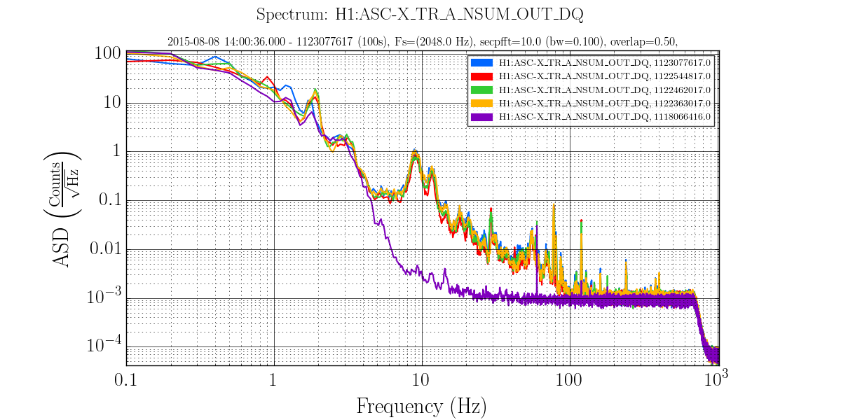
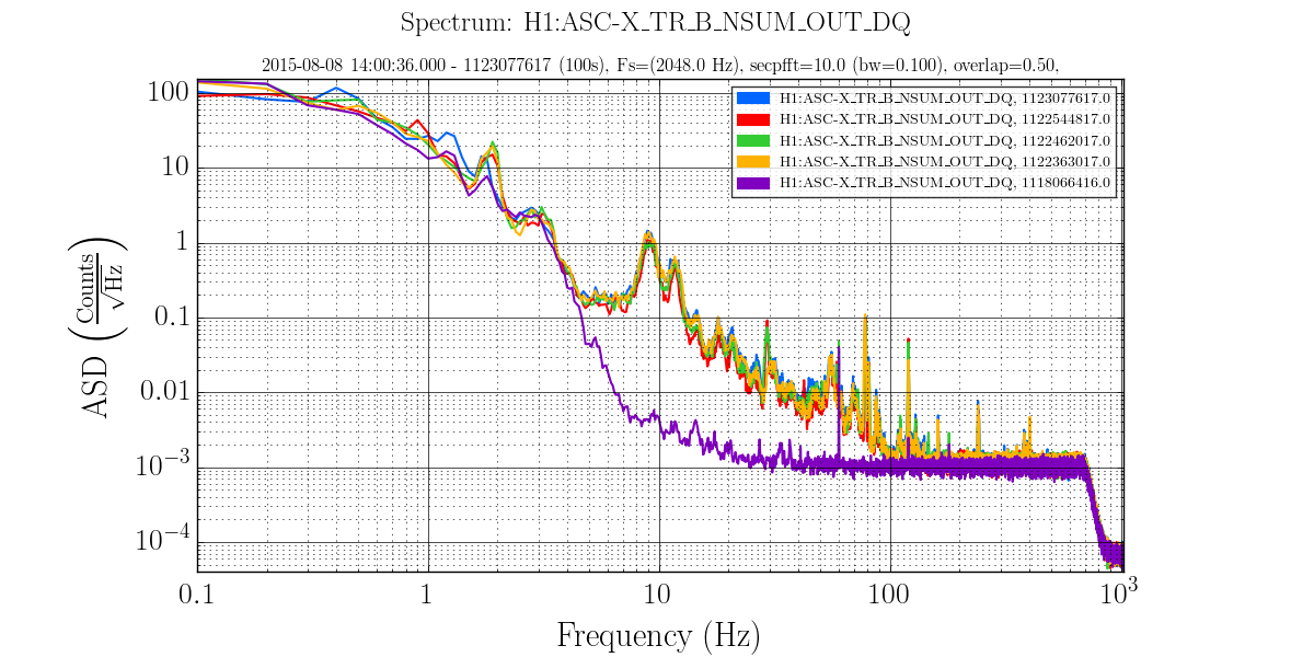
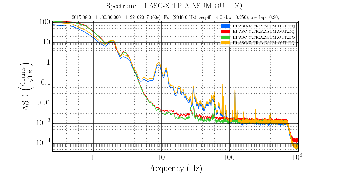
In following up the beam tube glitch injections, we by chance noticed that the amplitude spectrum of the NSUM of the ASC photodiodes at end X have changed significantly since ER7. In particular, through July and August there is now a set of peaks at 9 and 10.2Hz and broadband noise in ASC-X_TR that was not there in ER7. We don't see any significant changes in the corresponding Y_TR channels.
The UTC times for the following four plots are:
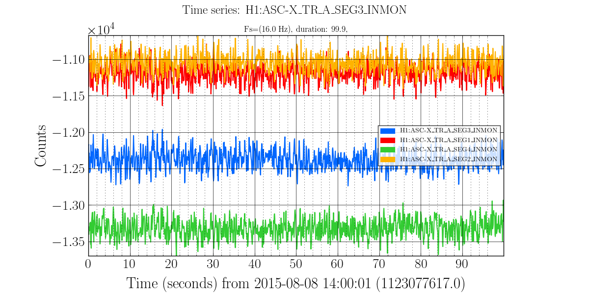
2015-08-08 14:00:00 (Blue) ("now")
2015-08-02 10:00:00 (Red)
2015-08-01 11:00:00 (Green)
2015-07-31 07:30:00 (Yellow)
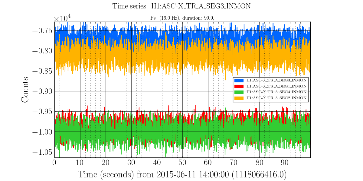
2015-06-11 14:00:00 (Purple) ("ER7")
Fig 1: ASD of X_TR_A_NSUM. (excess noise above 5 Hz)
Fig 2: ASD of X_TR_B_NSUM. (excess noise above 5 Hz)
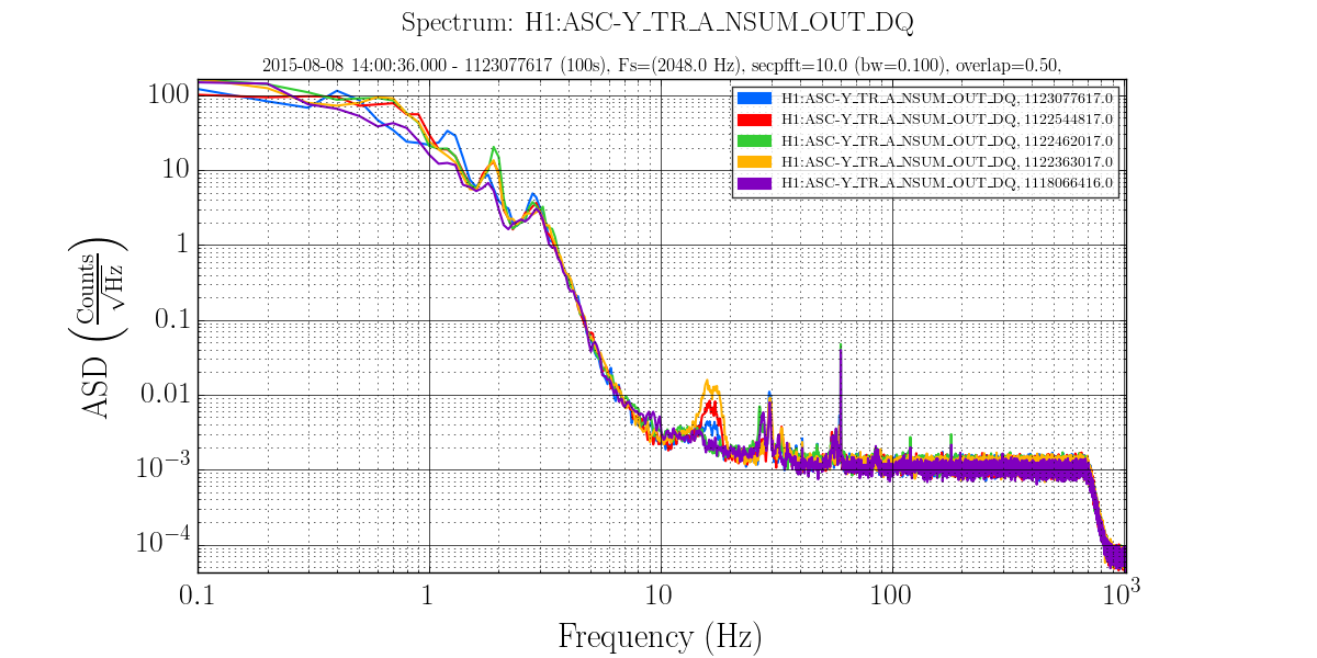
Fig 3: ASD of Y_TR_A_NSUM. (no major changes)
Fig 3: ASD of Y_TR_A_NSUM. (no major changes)
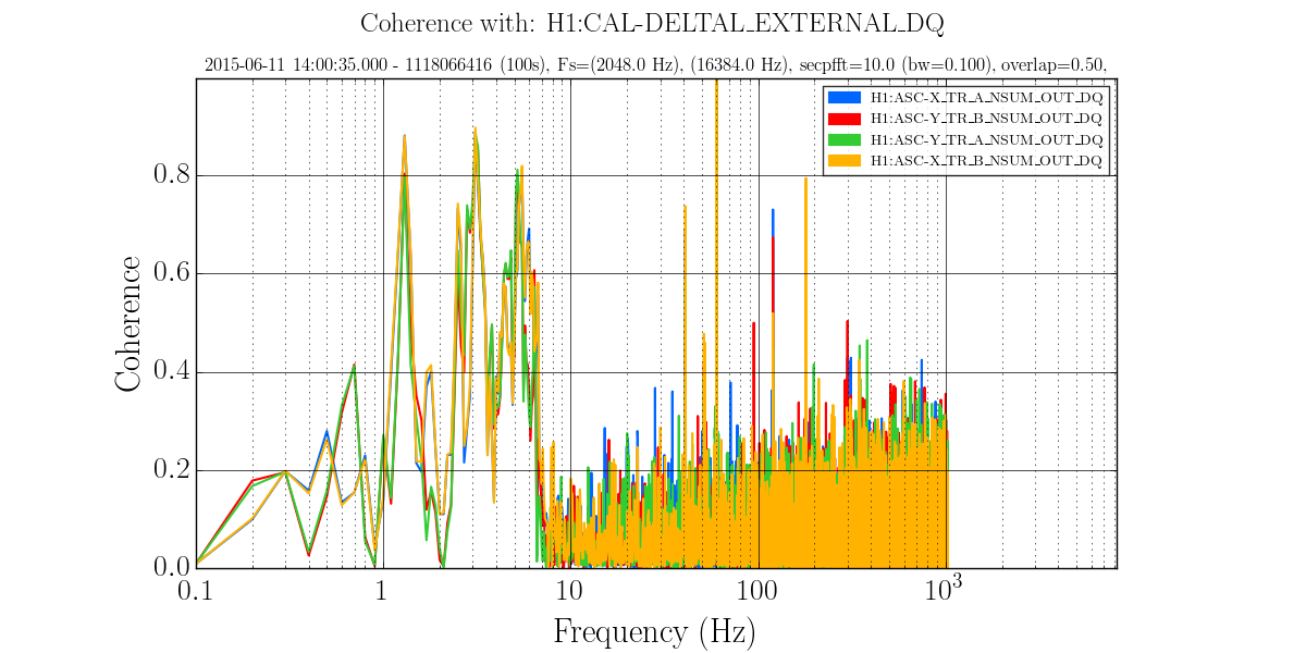
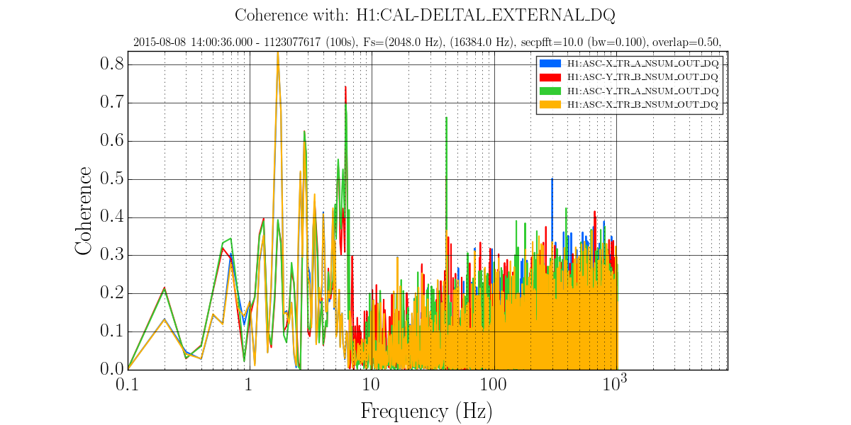
We note that this additional noise should be above the feedback frequency and indeed we see no increased coherence in DARM now, w/r/t ER7, except at 1.7Hz.
Fig 4: TR Coherence w/ DARM ER7 time.
Fig 5: TR Coherence w/ DARM now time.
We thought the most likely explanation would be poor alignment on the TR X ASC diode, coupling beam pointing noise into “fake” intensity noise. However, we don’t see anything obviously wrong with the DC values from the segments now.
Fig 6: Timeseries of TR segments ER7 time. (More light on 1 and 4)
Fig 7: Timeseries TR segments now time. (More light on 3 and 4)
We didn’t see this as a DQ problem anywhere, but wanted to report it in case it indicates some problem we haven’t thought of.
Images attached to this report
Comments related to this report
This was seen before, and may be related to broken electronics.
The excess noise is visible also on August 1, the first lock after Vern's percussive maintenance. So either the high frequency noise in the OSEMs came back a day later, or it wasn't related. The channels that have the 1821 Hz and harmonics are only recorded at 256 Hz, so I can't check whether the OSEM problem was there or not on Aug 1.
Images attached to this comment
FYI the same coils were oscillating this morning. Satellite box will be replaced.