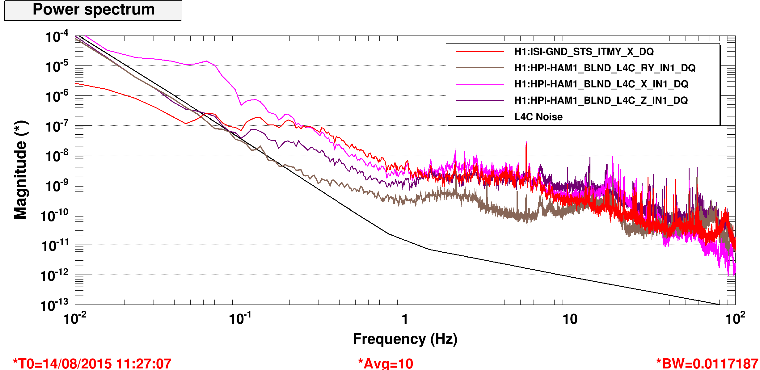
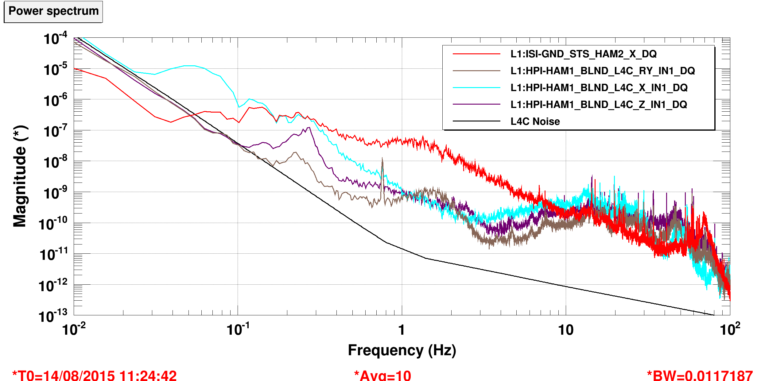
There is some suspicion that motion of the HAM1 table is contributing to CHARD noise. I learned today that LLO is using some inertial isolation on their HAM1 HEPI platform (i.e. they are blending L4Cs & IPSs, and use that signal for feedback control). I've started looking in to doing this here, but I wanted to see what kind of gains we could maybe expect from such a scheme. The two attached plots are (first image) LH0's HAM1 L4Cs versus our ground, and (second image) LLO's HAM1 L4C's versus their ground. A few points:
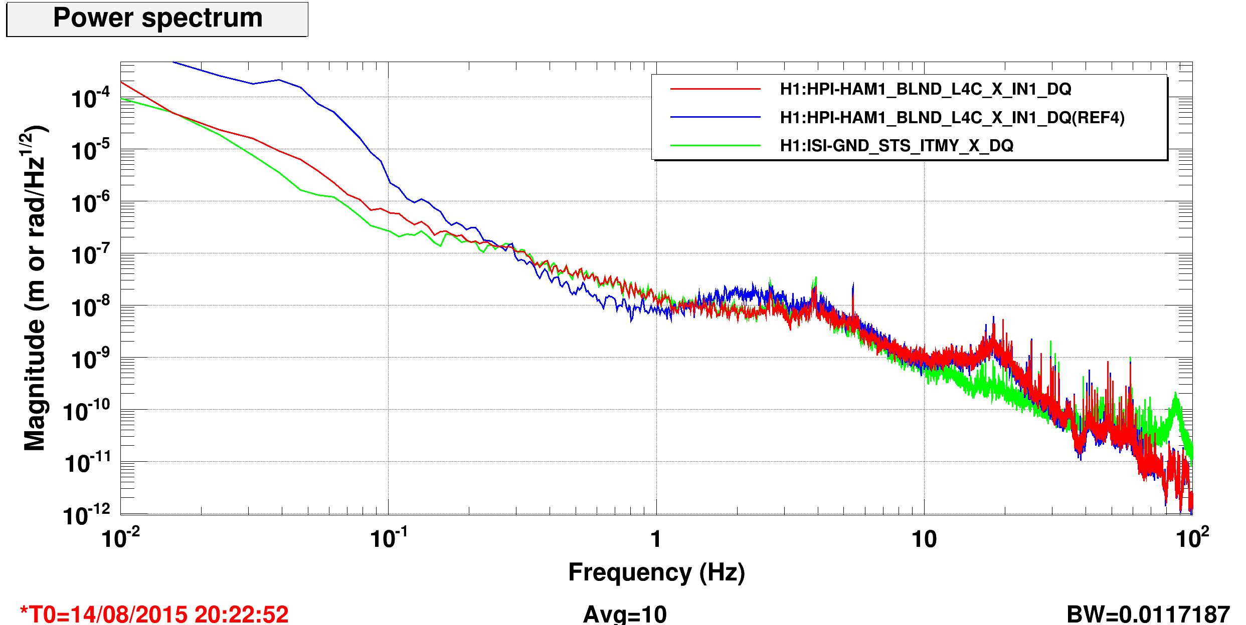
1. X at low frequencies at both sites sucks. I suspected sensor correction, my third image is an on/off comparison. X is a lot better with it off (blue is sensor correction off, red is on, green and brown are the grounds). We are getting hammered by wind right now but the performance is equally bad without sensor correction). I remember turning HAM1 sensor correction on a while ago, and did a measurement where I thought it was making an improvement at the time, so I'm not sure what happened here. Y is not as bad, but I've turned it off as well.
2. At 1 hz LHO is doing almost as well as LLO because our ground is quieter. Yay us.
3. The real improvement would come between 1-10hz, where LLO is moving less by ~1.5 orders of magnitude. This will mean installing blends, which is an easy copy paste with foton. Or if LLO was nice they'd send a mat file with a zpk. It wil also mean that we would need to redesign the isolation loops for a UGF above where we want isolation. Right now they are probably 2hz loops, I would guess that LLO's are probably 10-15.
The 2 actions I want to do before 01 are:
1. turn off X/Y sensor correction... which is done. I'll look at the filters and see if I can find whats wrong, but for now I would expect to leave this off. Z sensor correction seems to work fine.
2. Install the LLO blends and see if they make things better at least a little better around 1 hz, and not make things worse at low frequency. I would like to do this Monday.
After that I can look at redesigning the isolation loops, or maybe just copy LLO's, but I would worry that the higher frequency parts of the plant may be different.


