J. Oberling, P. King
Power Budget
We measured the power at several points around the PSL:
-
Power out of the NPRO: 1.508 W
-
Power into Amplifier: 1.08 W
-
Power incident on monitor PD: 0.83 mW
-
PD_AMP (Power out of the frontend): 34.0 W
-
Power reading from MEDM: 32.6 W
-
Power incident on PD: 0.5 mW
-
Requires recalibration
-
Power Monitor PD (Power out of the HPO box): 28.6 W
-
Power reading from MEDM: 28.6 W
-
Power incident on PD: 0.44 mW
-
Power into PMC
-
ISS on (7.5% Diff power): 27.0 W
-
ISS off (5% Diff power): 27.7 W
-
PMC_TRANS (ISS off, 5% Diff power): 25.5 W
-
Power reading from MEDM: 23.6 W
-
Requires recalibration
-
FSS RefCav TPD
-
Power incident on PD: 0.12 mW
-
Voltage reading on MEDM: 1.63 V
There are 2 PDs that need to be recalibrated: PD_AMP (which monitors the power out of the frontend) and PMC_TRANS (which monitors the power transmitted by the PMC). Due to time constraints and interference with IFO recovery and commissioning activities (have to turn the ISS off to recalibrate PMC_TRANS), the recalibration has not been performed yet. Will be done ASAP.
HPO Contamination Check and Green Light Inspection
Since we had to take the lid off the HPO box to measure PD_AMP, we also inspected the inside of the box for contamination. This is something that had been on our radar to do next time we opened the HPO box. Matt had noticed back in April (see LLO alog 17972) that the LLO HPO box had a large amount of contamination, specifically underneath the holes where the lid is screwed down to the box itself. We also noticed some particulate underneath the screw holes, but not to the extent that was seen at LLO. Peter took pictures and will post them. We went ahead and wiped the screw holes, lid holes, and screws themselves with wet IPA wipes.
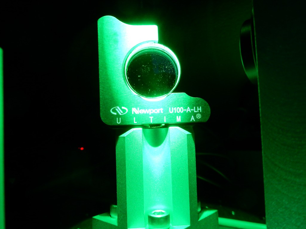
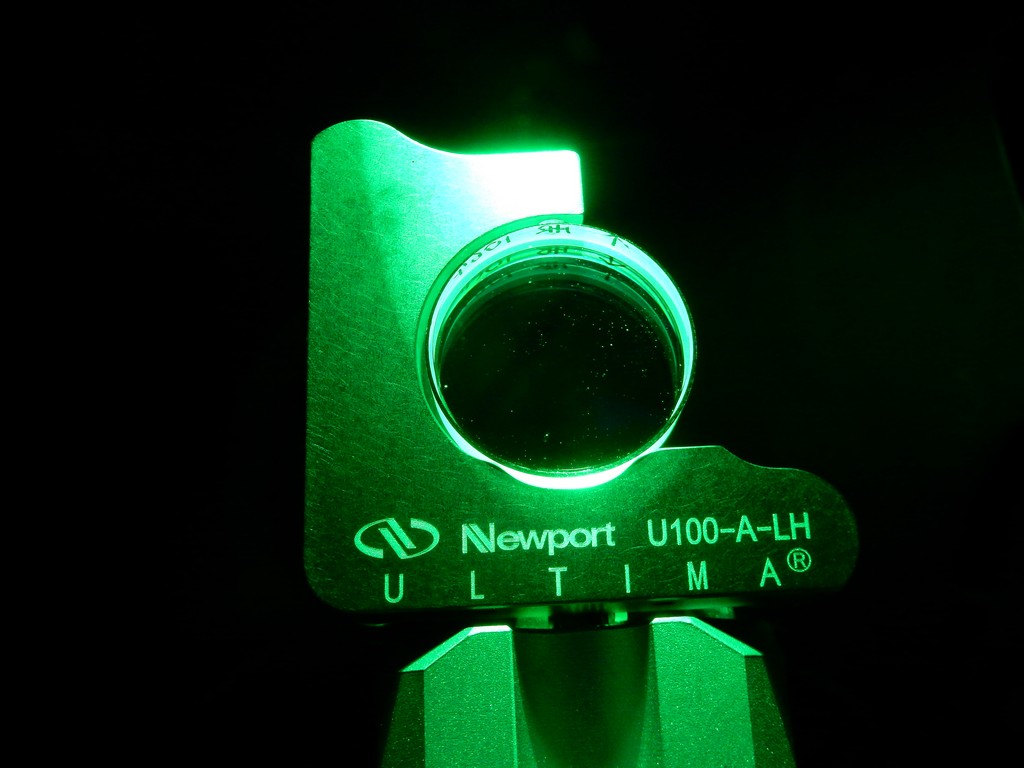
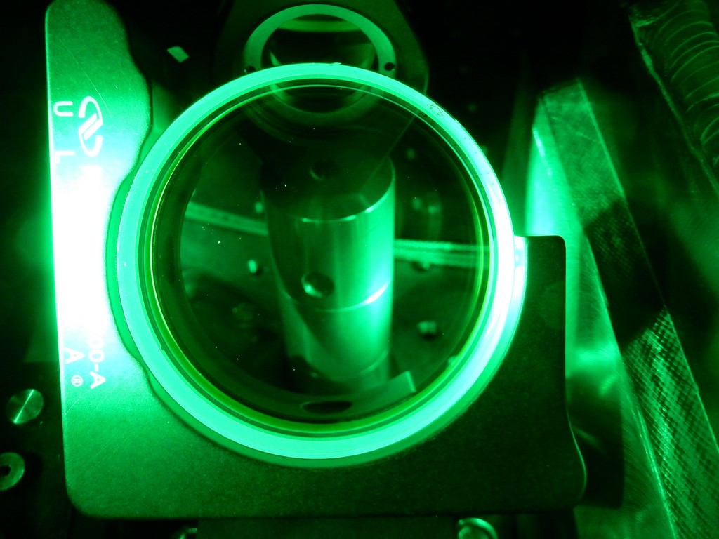
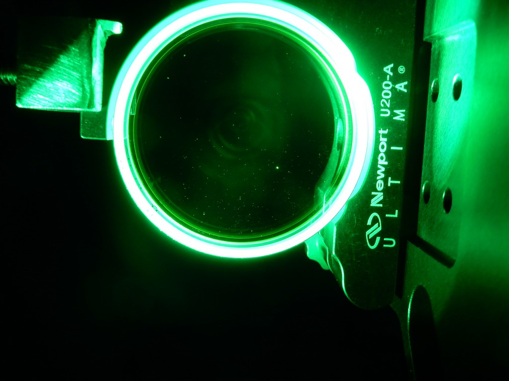
We also tood one of the green flashlights and looked at a few optics to get a feel for general PSL contamination. All and all it wasn't too bad, once again nothing like was seen at LLO. Peter took some pictures of mirror M26 (in the FSS path), and the top and bottom mirrors from the IO periscope. We used a couple small puffs of air to see if we could dislodge some of the dust on M26; this was successful (see pictures). We also looked at the PMC mirrors with the green light; these looked clean, we couldn't see any dust.
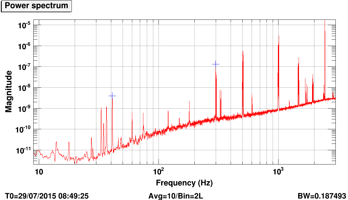
Modified TTFSS Box Round 2
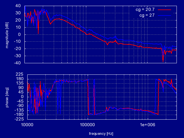
Peter had made some more modifications to one of the spare TTFSS boxes (same one we used last week, see LHO alog 19872), so we installed it again. Unlike last time, the FSS would not lock with the modified box installed. It would seem like it was about to lock, we could see flashes of the 00 mode as the NPRO frequency was changed, but it wouldn't lock onto it. At this time we aren't sure as to why. We reinstalled the original TTFSS box and the FSS locked without issue. We measured the UGF at 2 different Common Gain settings (Fast Gain was constant at 22.2 dB):
-
Common Gain = 27.0 dB
-
UGF: 644.7 kHz
-
Phase margin: 47°
-
Common Gain = 20.7 dB
-
UGF: 198.8 kHz
-
Phase margin: 34°
Peter has the data for these measurements and will post it as a comment. We restored the Common and Fast gain settings to their original values of 20.7 dB and 22.2 dB, respectively. Will investigate why the modified TTFSS box was not working.