Sheila, Gabriele, Elli, Evan
The message:
We think that some of the trouble we've been having with ASC could be because the sensing matrix for AS36 can change quite a lot when the alignment changes, and our DC coupled oplev servo on SR3 PIT has been introducing an alignment drift. A drift of 0.3 urad in SR3 seems to have caused many of our headaches this week. On the one hand it seems silly that we were not resetting the oplev offset regularly (that was my fault), but on the other hand it seems strange that a rather small misalignment can change our sensing matrix this much.
The problems:
We've had a long history of changing the input matrix for AS36 I to SRM, rephasing AS 36 WFS . This has seemed mysterious at times, that the matrix we need changes as we power up, and that once a month or so we have had to retune them.
This week we have had a particularly bad time with alignment related problems. Monday we had a temperature excursion in the PSL, and the periscope PZT lost power (20396), after this something has changed in the PMC (20490), and the spot position on IM4 trans moved. Although we think the change was upstream of the IMs we were unable to fix it with the PZT and mode cleaner mirrors. Yesterday we moved IM3 to bring the spot back to the same position on IM4 trans. We've had fast locklosses within 10 minutes of powering up (20465), the pernicious 0.46 Hz instability that can be fixed by increasing DHARD PIT gain (20404), several changes of the sensing matrix for AS36 (20465 20512 20497), huge nonstationary noise with high CHARD bandwidth, and coherence with CHARD drive signals in DARM that came and went with the non stationary noise (20497).
This morning TJ, Jim, and other operators were losing lock in the ENGAGE ASC state. With Gabriele they traced it down to the change in the SRC matrix. Yesterday we found that AS36 A I was the best signal to use for SRM control as we powered up, by watching all the error signals as we powered up, moving SRM to maximize build ups and choosing a signal that responded to SRM and had a zero crossing in a good location. This morning the same method of choosing an error signal indicated that we should use only AS36 B I.
Gabriele and I saw that the signal we were using for BS control was sensitve to SRM moving. At 3 Watts we opened both the BS and SRM loops, and found a matrix that would make the BS signal insenstive to SRM motion.
While Gabriele and I were checking the sensing for AS36 as we increased the power, Elli noticed that SR2 and SRM witness sensors had moved between midnight UTC on August 10th and August 11th, which is approximately coincident with the start of these problems. After we lost lock, I restored SRM and SR2 pitch to their previous locations based on the witness sensors, and locked SRY, first with the DC coupled oplev on then with it off. The spot on AS_C was off in pitch by about half a beam width, and came back to nearly centered when I turned off the DC coupling on the oplev servo. The moves all in pitch were: SR3 -0.3 urad, SR2 +6 urad.
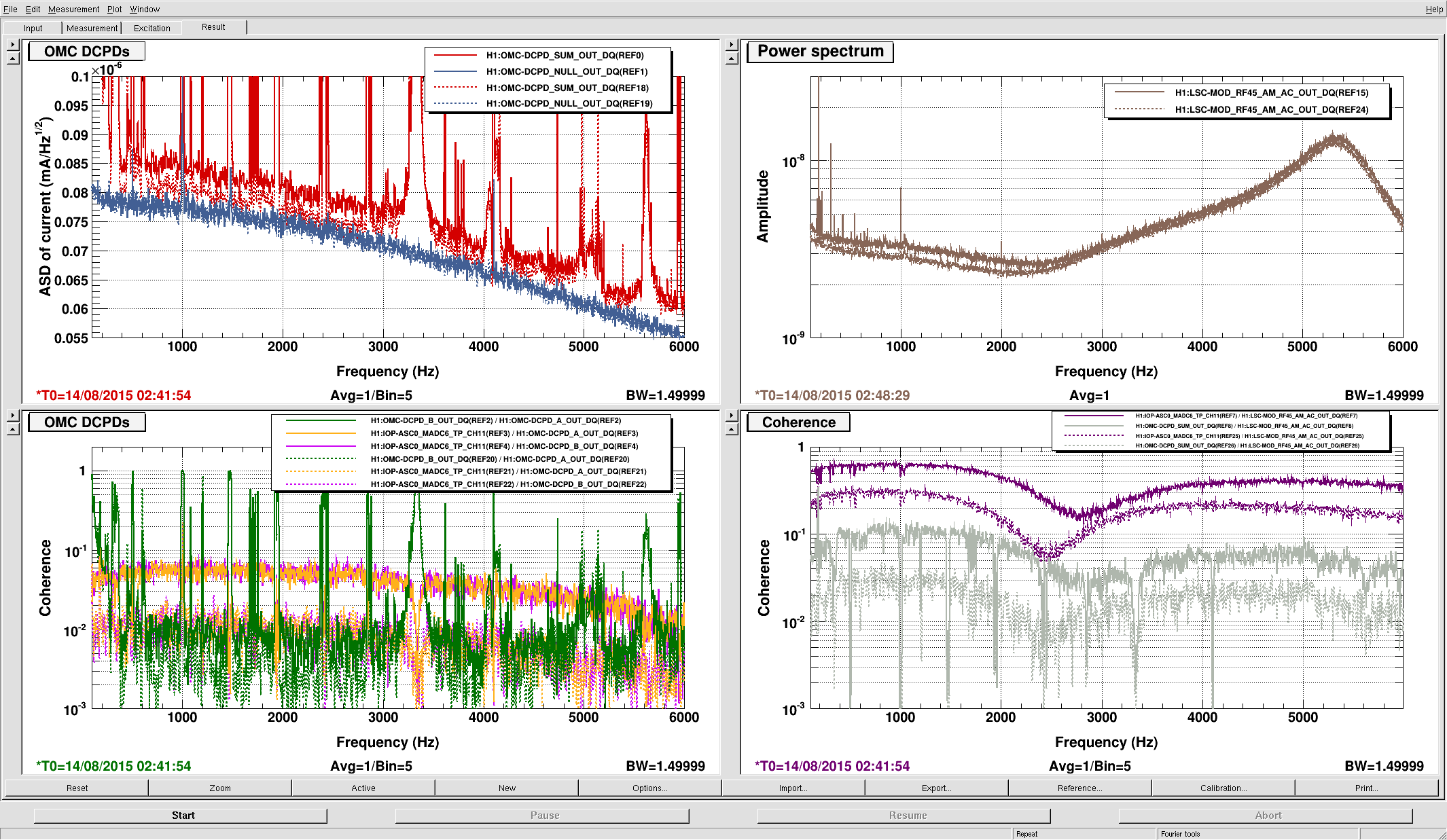
After we reset the offset and relocked, the BS signal (AS B 36 I) was insensitive to SRM alingment, and the input matrix for SRM yaw that seems good is the same as what we had last week and for several weeks previous: -3 for AS A 36 I and 1 for AS B 36 I. We have been stable throughout power up since this. The coherence with CHARD is greatly reduced, and mostly below 20 Hz. The spectrum is more stationary, but we still have some non stationarity. Gabriele looked at a spectrogram and a coherence gram, and sees that the non stationary noise in DARM no longer coresponds to times when the coherence with CHARD is high.
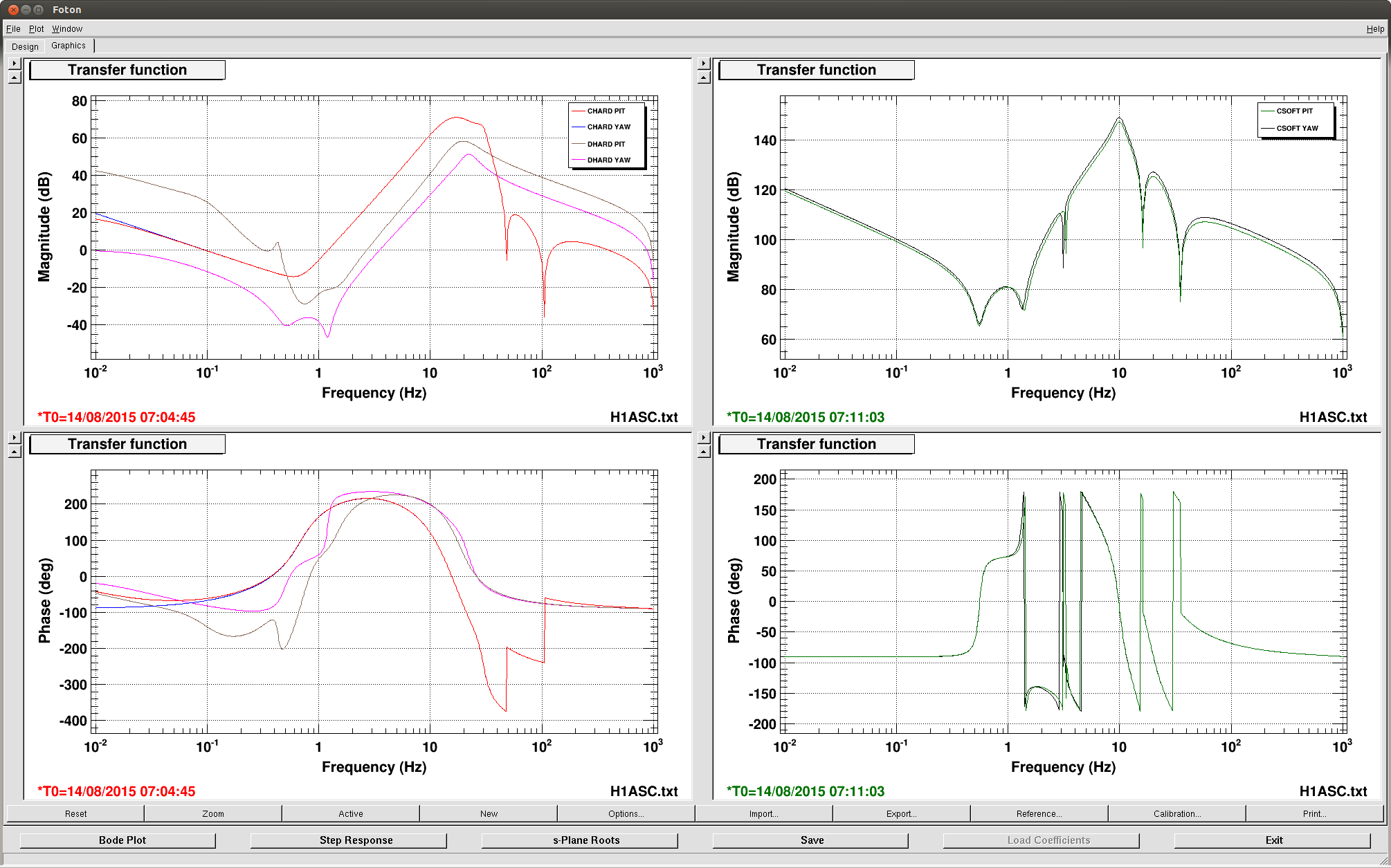
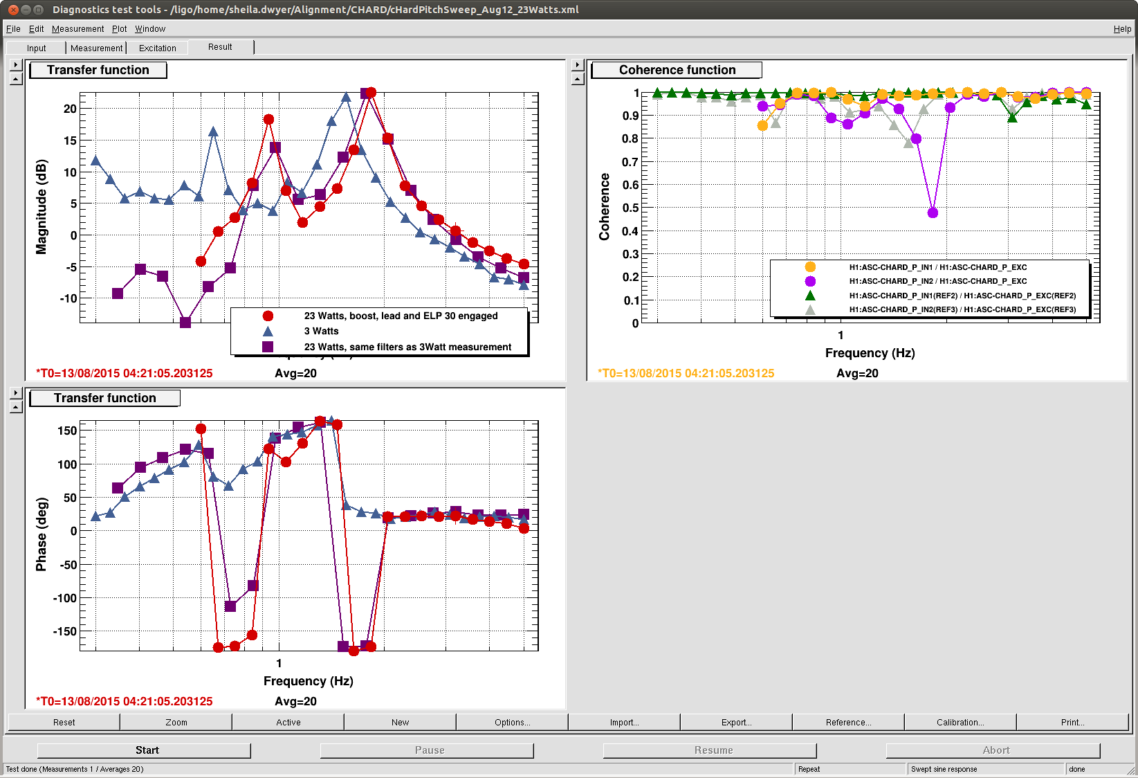
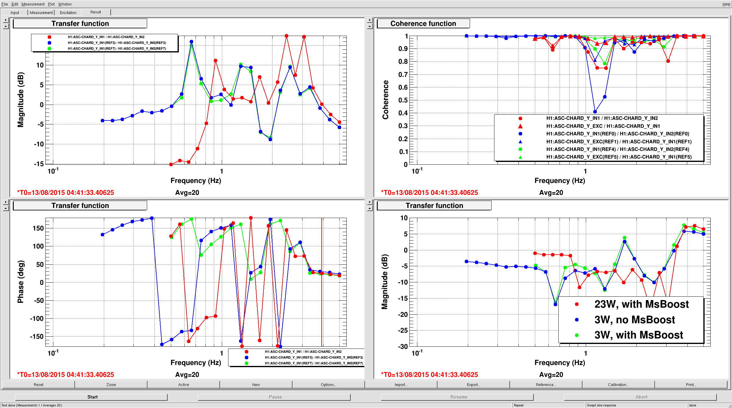
Since moving SR3 we have had the 0.46 Hz instability again. This time Evan added a ResG in DHARD P to give us some gain at that frequency (instead of increasing the FM gain which leaves us with very little phase margin). We plan to add this to the 23Wboost filter that gets turned on when we power up.


