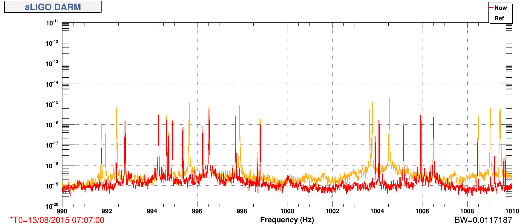
The main story of the day is related to the non stationary low frequency noise first seen early in the morning. It seems to come from CHARD noise, which could be coupling to DARM more now because of a change in alignment.
- Once we were stable at 24 Watts this afternoon, we didn't see the terrible low frequency noise that was seen in the early morning (at least it was not as bad).
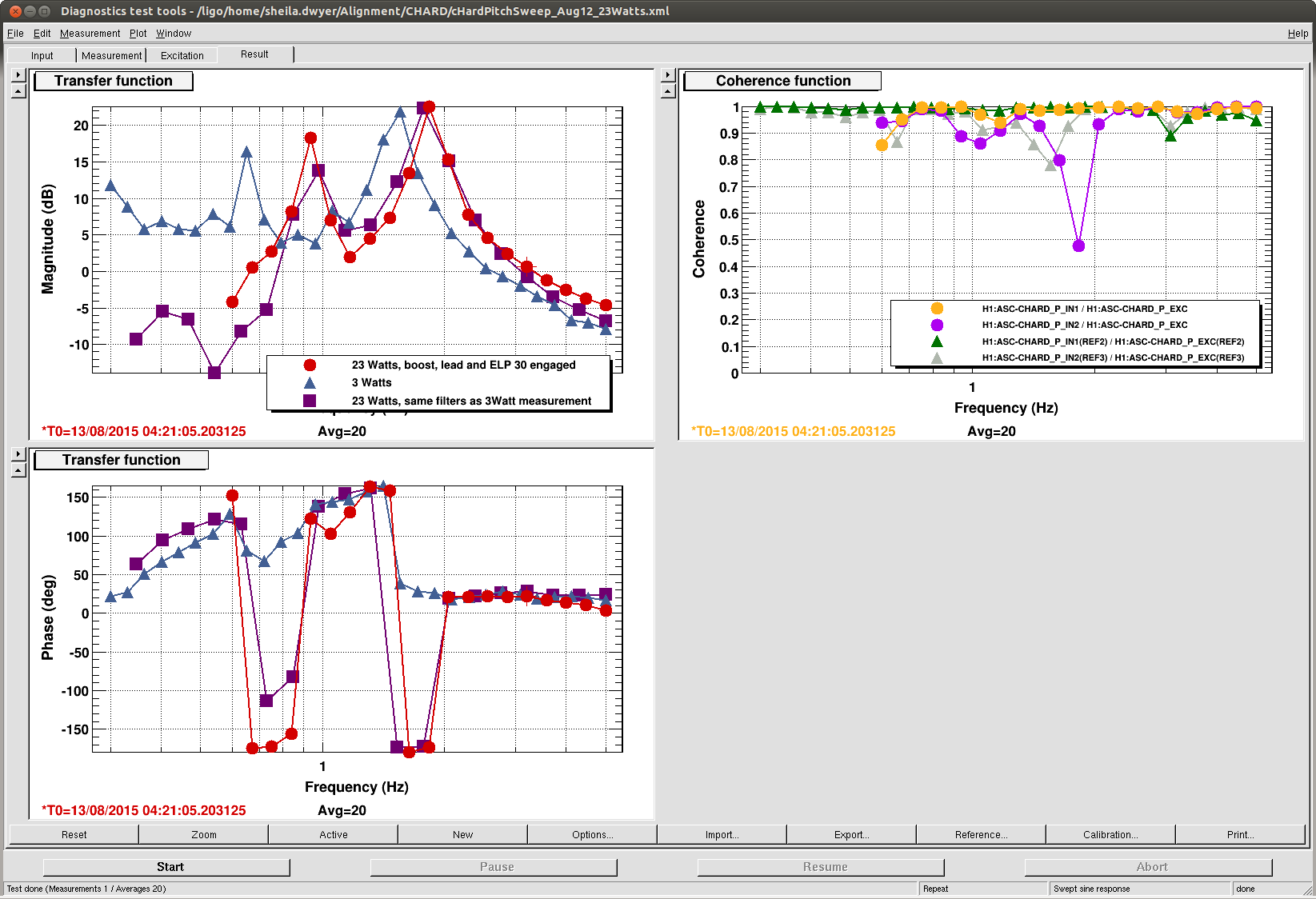
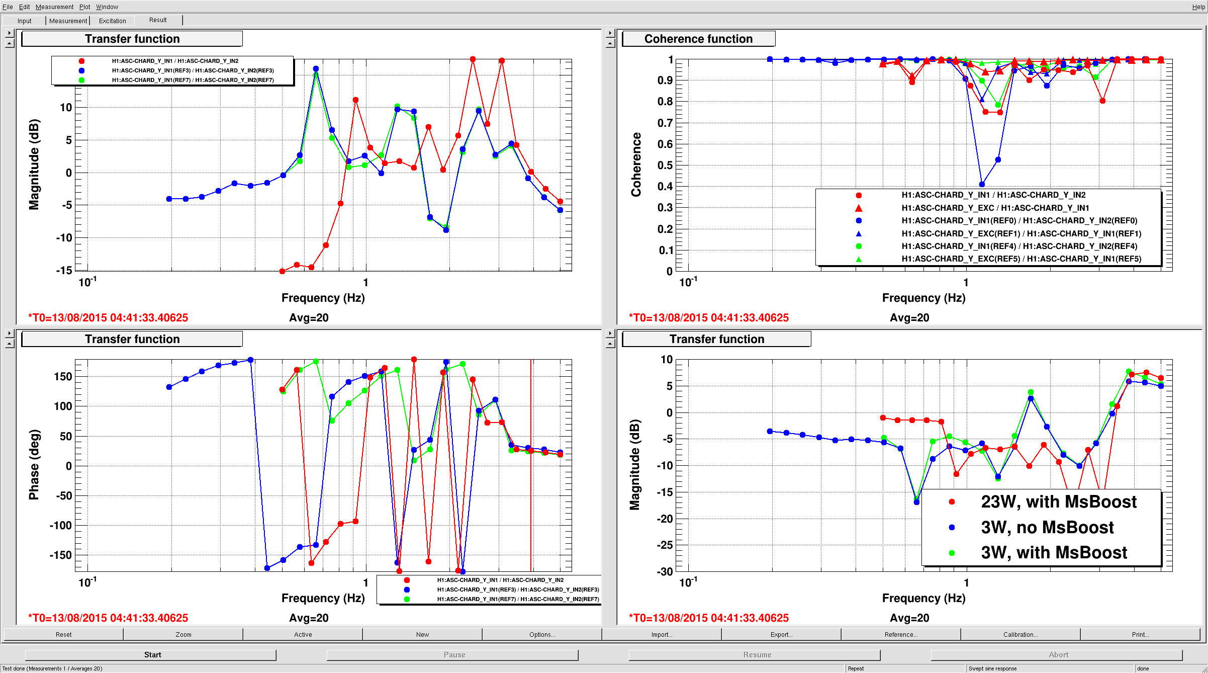
- Jenne and I worked a bit more on the CHARD loops, adding 23 Watt boosts, a lead filter that gave us some phase to make cut offs. The first attached screen shot is a comparison of CHARD PIT at 3 Watts, and at 24 Watts before and after the changes. Jenne has similar measurements for yaw.
- The terrible low frequency noise came back.
- We undid all of the CHARD changes we made yesterday and this afternoon(keeping only the leads and cut offs) . The terrible low frequency noise did get better, although some extra non stationary low frequency noise remains below 50 Hz. The non statinary noise was reduced when we did this, although we still had some excess non stationary noise below 50 Hz, and coherence with CHARD. We did another round of on/off test to be sure CHARD was involved.
- We decided to check on alignments that we thought moved durring monday's PZT power off and PSL temperature excursions. We could see that we had moved on IM4 trans after monday, so in full lock we moved IM3 to bring ourselves back to the old location on IM4 trans.
- We then redid inital alingment, carefully, and relocked, using the low bandwidth CHARD loops and our new cutoffs. After this the noise does seem better, but there is still excess noise that is non stationary.
A few ideas for next steps:
- see if we can find a better CHARD sensor. Do we need to use trans mon QPDs or is there a way to find a better SNR on the refl WFS?
- can we do a better job with A2L?
- We could try to change our alignment to see if we can reduce this noise.
- DHARD resonant gain for the 0.46 Hz instability. This instability only seems to come up when we have a bad alignment, but a little more gain can probably help us avoid it.
We also worked on a few other things today...
- Between Evan and I we reverted the phase of the 45 WFS to what they were a week ago (before TCS tuning)
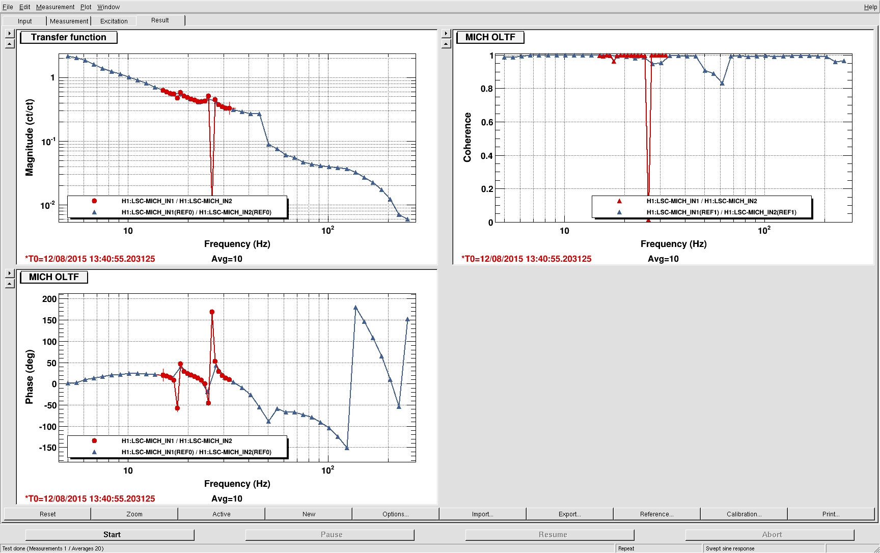
- Gabriele and I saw this morning that we think that a SRC1 YAW input matrix of -3 for AS A 36 I and no signal from AS B is good. We watched all of the AS 36 Yaw signals as we powered up to 17 Watts, and saw that AS B sees something that drifts as we power up. When we removed AS B from the input matrix, the AS 90 power increased.
- The SRC2 Yaw loop was painfully slow (several minutes reaction time). It now has a factor of 2 more gain (-40 is fm gain now, it was -20 before). This is in gaurdian.
- Gabriele had a look at doing frequency dependent A2L for ETMX. We have reverted it for now, but it seemed promising.
- Our locks today seem quite stable, we have been loosing lock by making mistakes, and when we have a combination of driven measurements and PEM injections.
- ETMY ESD LP had been turned off at some point, most likely unintentionally. It's on again, and now monitored in SDF. We also turned the PUM coil drivers back to their low noise state. We needed more range for DHARD when the roll mode was rung up very badly last week (because of DOWN not runnning for extended of periods of time twice.) These were a mixed bag of monitored and not in SDF, I think I've set them all to monitored now, with the requested state as 3. However, this gets over written by the gaurdian.
- I had put offloading of full lock ASC in the normal guardian path, but this seemed to make the DRMI alingments for relocking worse (possibly because the full lock ASC is compensating for some wire heating). So it is now removed from the normal path, but can be choosen as an option after transitioning to DC readout.
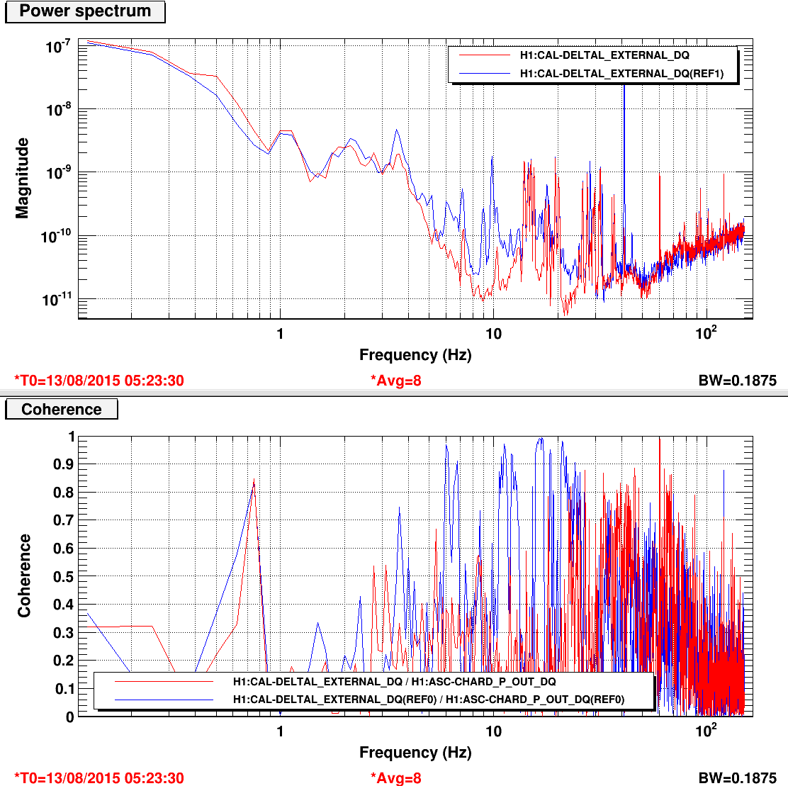
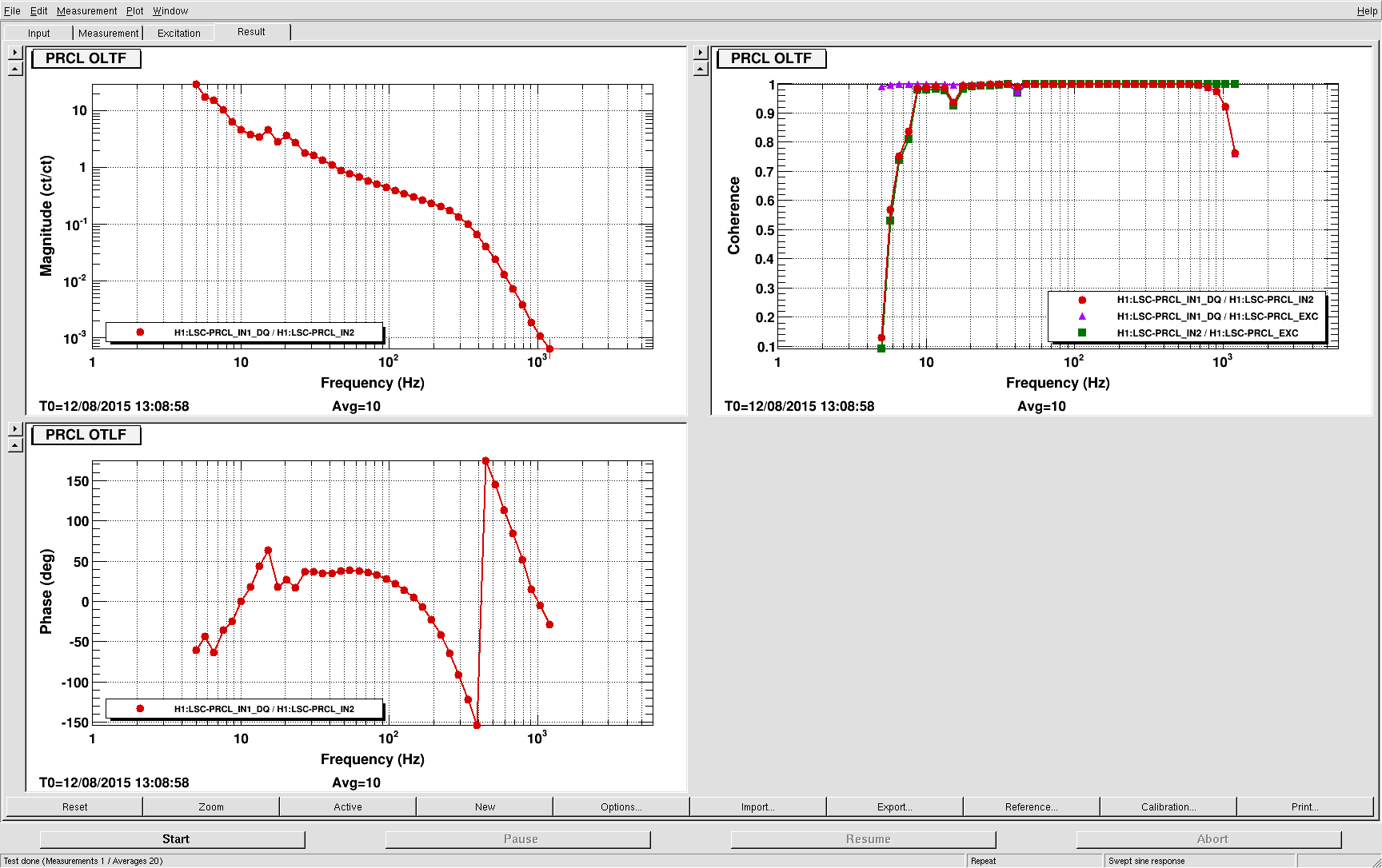
Here is a measurement of CHARD Yaw at high power, overlaid with yesterday's measurements at 23W. The 23W measurement includes the MsBoost, but not any 23W boost or the lead-plus-cutoff filters that Sheila designed.
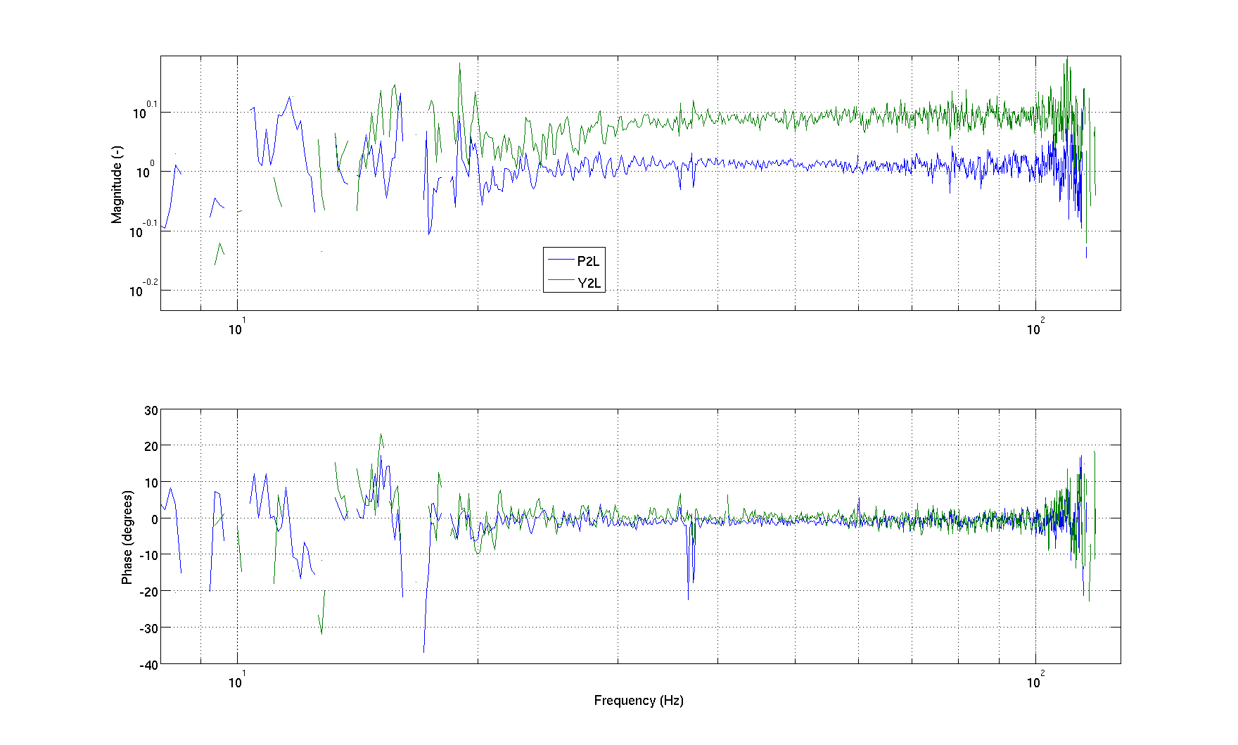
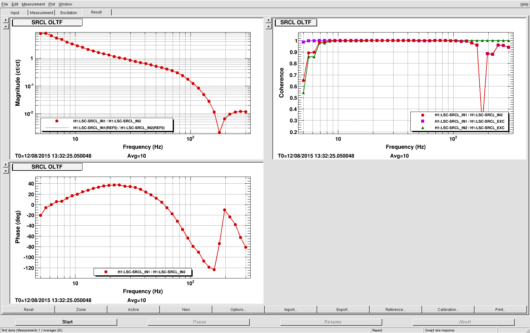
Here is how I retuned the A2L. I injected some band limited noise (ellip band pass 1-100 Hz, amplitude 20000 cts) on ETMX_L2 L2L, P2P and Y2Y paths, with the P2L and Y2L gains set to zero. The measurements were good between 20 and 100 Hz. The ratios -P2P/L2L and -Y2Y/L2L are what we need to implement in the correction paths. Those trasnfer functions are quite constant above 30 Hz, but not so much below 30 Hz. We would need a better (sweep sine) measurement if we want to improve the decoupling below 20 Hz.
I changed the gains of the P2L and Y2L of ETMX as follows:
P2L from 1.18 to 1.03
Y2L from 1.33 to 1.23
Coherence of DARM with CHARD reduced at low frequency. However, we reverted to the old numbers to investigate the low frequency non stationary noise.