For Maintenance, we took all HEPI's and ISI's to OFFLINE.
I requested OFFLINE for BSC1 but it stalled and did not go there.
Jim helped, and got it to go OFFLINE.
TJ and I looked into why this happened, and what happened, and here's the list of events:
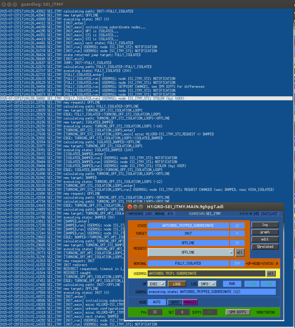
ITMY BSC1, Request for OFFLINE at 15:13 did not execute:
- SEI_ITMY request for OFFLINE did not take it to OFFLINE
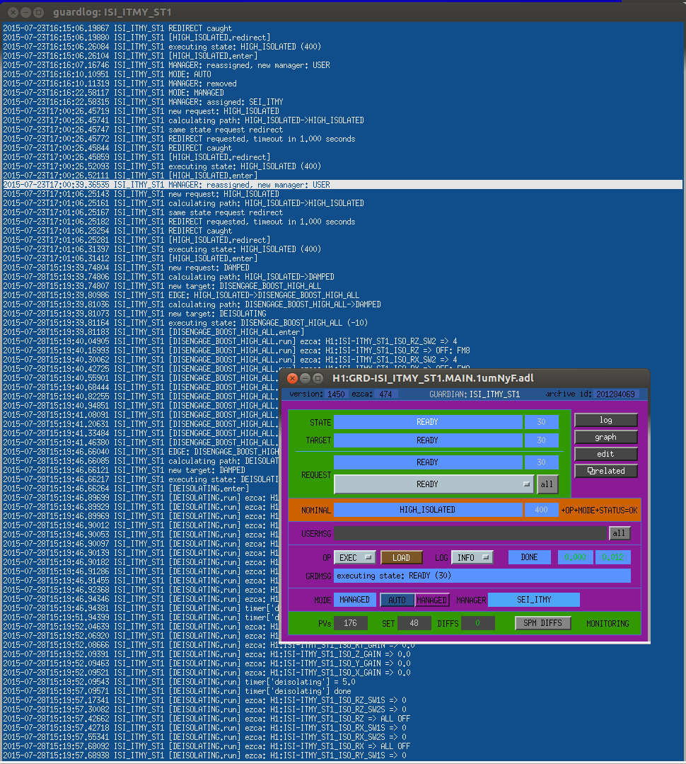
- ISI_ITMY_ST1 left in Managed by User on 7/23 (found in the log, Tj and Cheryl)
- ISI_ITMY_ST1 Managed by User prevents SEI_ITMY from taking it OFFLINE
- the fix was that Jim requested INIT on SEI_ITMY
- this changed ISI_ITMY_ST1 from managed by User to managed by SEI_ITMY
- HOWEVER, HEPI was in transition to OFFLINE, and the INIT request interrupted that and sent HEPI back to the previous state, ROBUST_ISOLATED
- This brought HEPI back up when we wanted it OFFLINE
- Jim requested INIT again
- Jim requested OFFLINE again
- these second INIT/OFFLINE requests allowed SEI_ITMY to bring HEPI and ST1 and ST2 to OFFLINE
My questions:
- do we always want Guardian to default to the previous state, as HEPI did when Guardian didn't recognize it's current state? This feature is what sent HEPI back up to ROBUST_ISOLATED when we were trying to reach OFFLINE.
- today I saw that my request for OFFLINE on SEI_ITMY wasn't really able to take the system OFFLINE, so is this an anomaly or something we need to plan for, or is the default procedure to INIT a system, reseting everything to Managed by Guardian (SEI_ITMY in this case)?
- Jim, TJ, Cheryl
My questions:
- do we always want Guardian to default to the previous state, as HEPI did when Guardian didn't recognize it's current state? This feature is what sent HEPI back up to ROBUST_ISOLATED when we were trying to reach OFFLINE.
Be specific about what you mean by "Guardian didn't recognize it's current state". It sounds like HPI_ITMY was always in full control of HEPI, and was reporting it's state correctly. SEI_ITMY was a bit confused since one of its subordinates was stolen, but I think it still understood what states the subordinates were in.
When INIT is requested the request is reset to what it was previously right after it jumps to INIT. Presumably SEI_ITMY's request was something that called for HPI to be ROBUST_ISOLATED when INIT was requested.
- today I saw that my request for OFFLINE on SEI_ITMY wasn't really able to take the system OFFLINE, so is this an anomaly or something we need to plan for, or is the default procedure to INIT a system, reseting everything to Managed by Guardian (SEI_ITMY in this case)?
This should be considered an anomaly. Someone in the control room had manually intervened with the ITMY SEI system, thus ISI_ITMY_ST1 reporting "USER" as the manager. The intervening user should have reset the system back to it's nominal configuration (ISI_ITMY_ST1 managed by "SEI_ITMY") when they were done, which would have prevented this issue from occurring.
All of the problems here were caused by someone intervening in guardian and not reseting it properly. Guardian has specifically been programmed to not second guess the users. In that case the users have to be conscientious to reset things appropriately when they're done.