sheila.dwyer@LIGO.ORG - posted 17:45, Tuesday 30 June 2015 - last comment - 10:41, Wednesday 01 July 2015(19401)
MC2 M3 LL zero crossing glitches
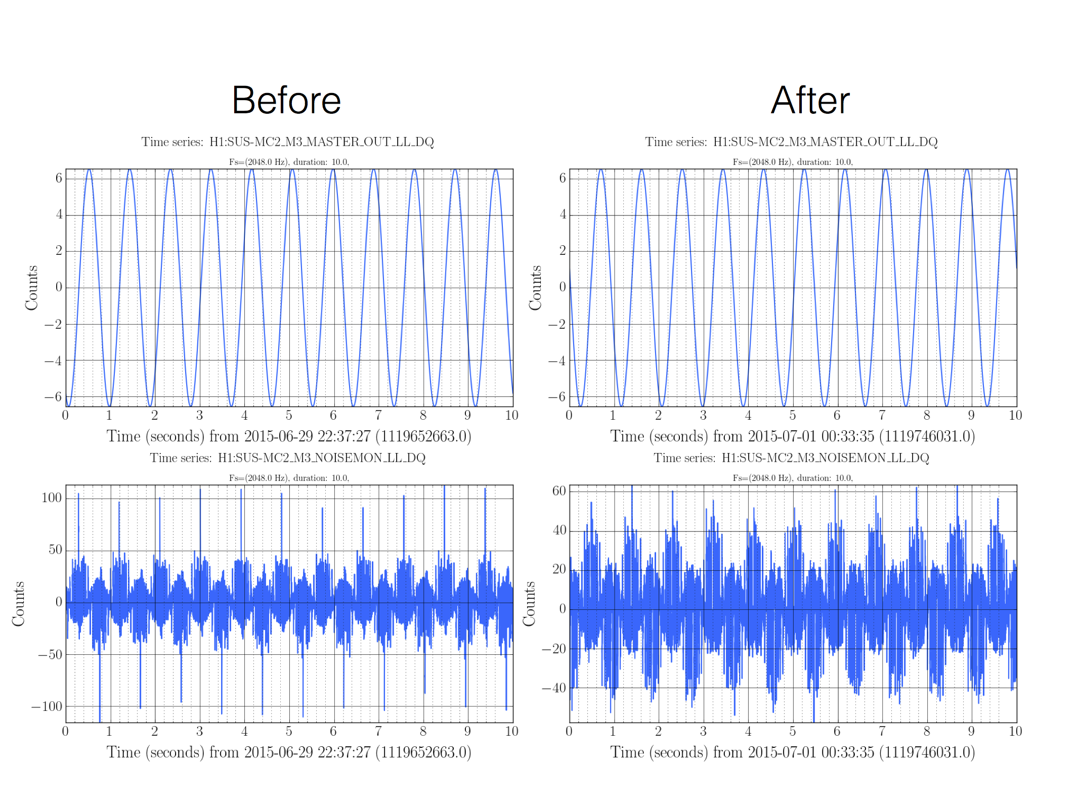
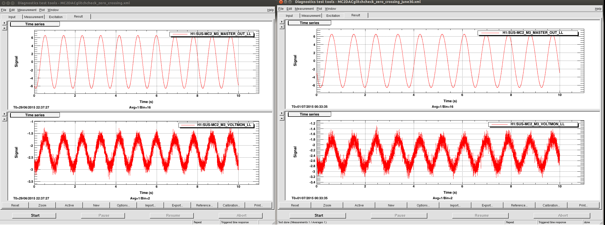
I sent a small excitation into MC2 M3 LL last night (29/06/2015 22:37 UTC) and again today after the autocalibration was done (7/1/2015 00:35 UTC).
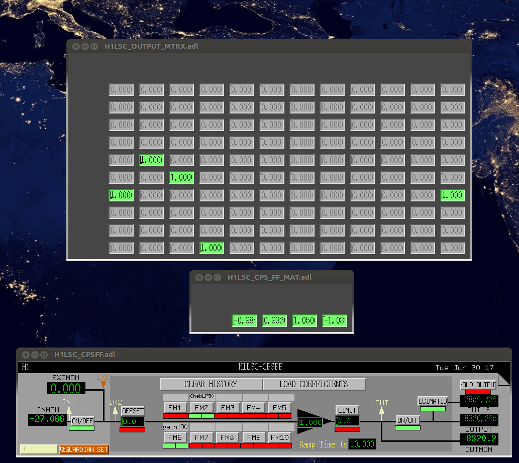
The attached screenshot shows the voltmon channel, both before and after. There isn't a clear difference, it seems like there could be a discontinuity at the zero crossing in both cases, but it is not obvious from the time series if things are better or not after the autocalibration.
Images attached to this report
Comments related to this report
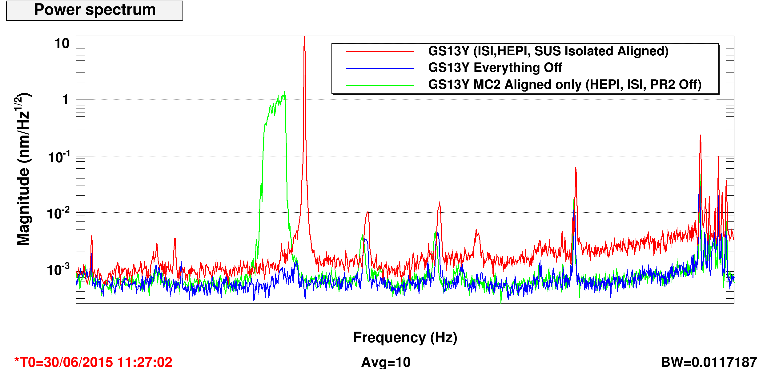
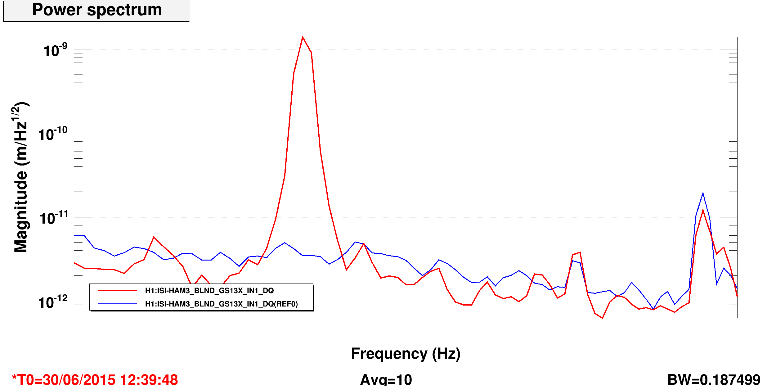
Hi Sheila, looks like your autocal did reduce the glitches somewhat between those two times. In the attached file I used the NOISEMON channels in the frames. But you could also watch the FASTIMON channels during injections from on site (thanks TJ).
Images attached to this comment