Things that probably happened, but of no impact to the IFO:
- WP5377 - Bubba, fan, LSB
Things that happened:
- EY to check SUS ESD cables, Andres, started 8:34AM, done 10AM, no cables changed
- WP5379 - JeffK, SUS and SEI IPC - done 9:00AM
- HEPI EY transition, Jim, started 9AM, done 10:49AM
- HEPI, Hugh, to EY, started 10AM, done 10:49AM
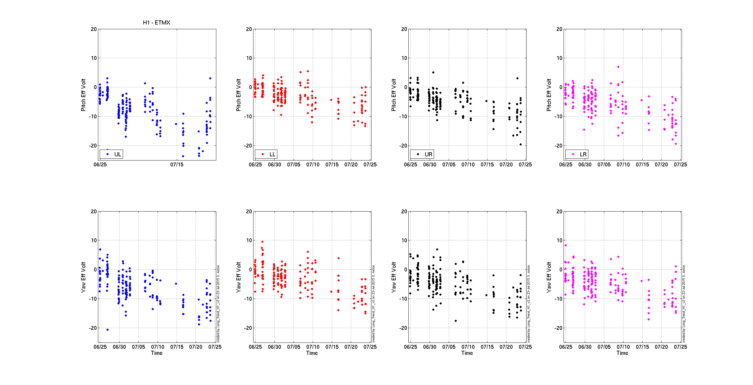
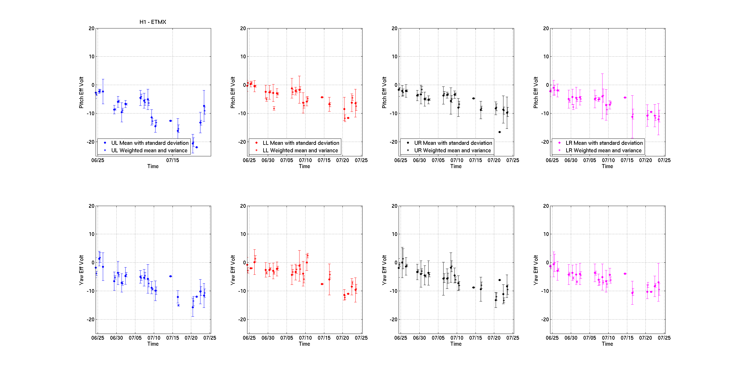
- ETMX charge measurement, Leo, started 9:50AM, done 10:54
- HEPI blend filters, Jim, EX, done 10:55
- WP5381 - Richard, Vault Seismometer, started 9AM, done 10:43AM
- High Bay door opened, Andres, 11:10AM
- WP5378 - Daniel, Beckoff, started 9AM, done 11:25
- PEM, mid-Y and EY, Vinney, started 10:46AM - done 11:34AM
- WP5350, Jason, PSL PMC, PMC and FSS electronics, Done 12:30
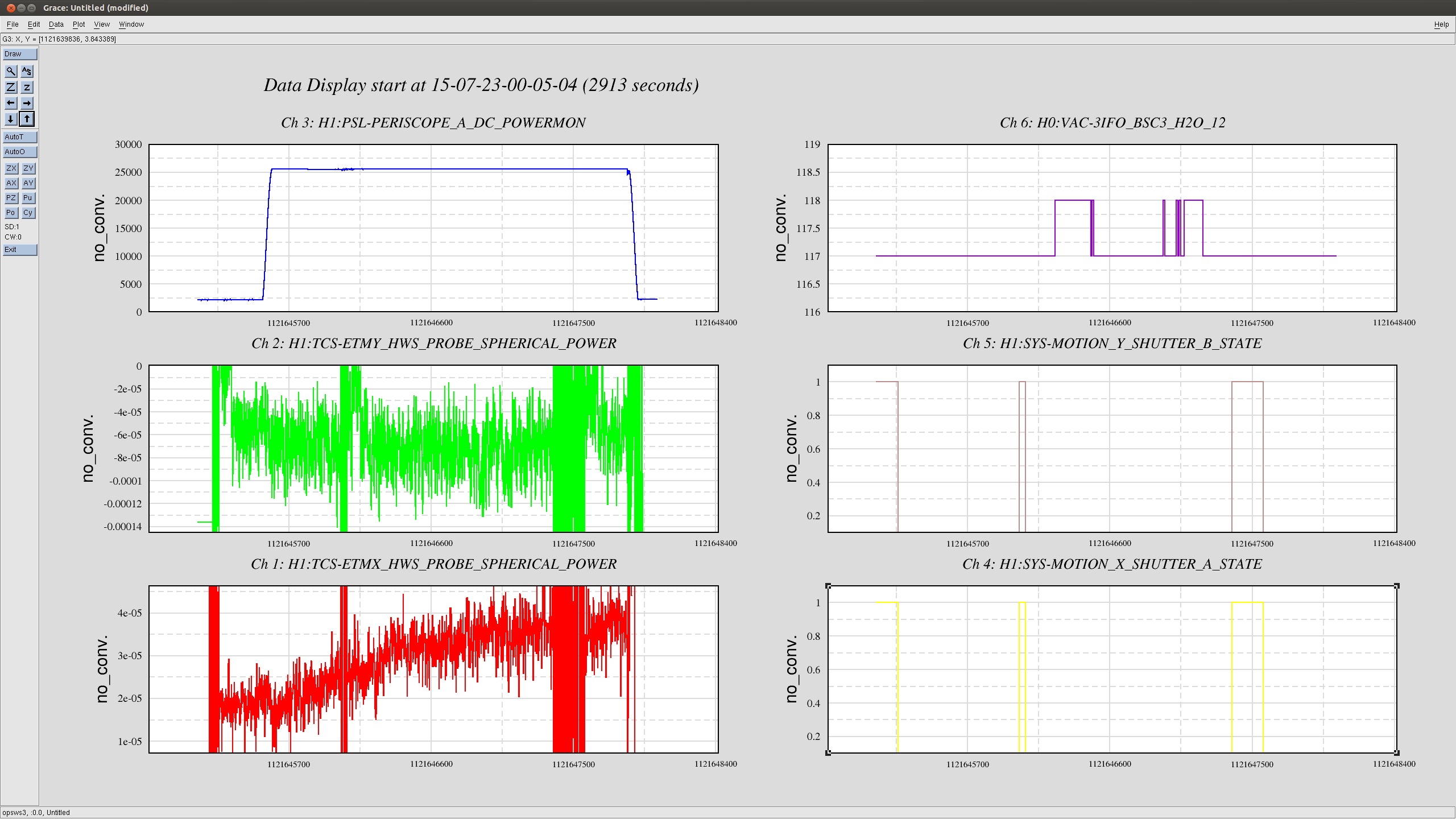
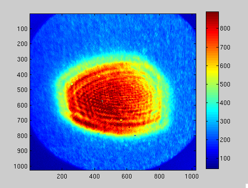
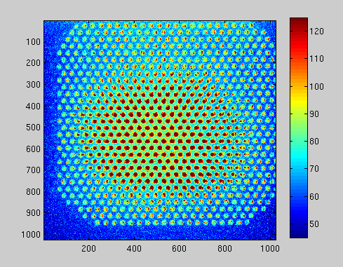
- TCS, Nutsinee, TCSX HWS align, started 10:50AM, Done 12:30
- WP5376 - Jonathan, CDS EPICS Gateway, started 8:24AM - assumed done
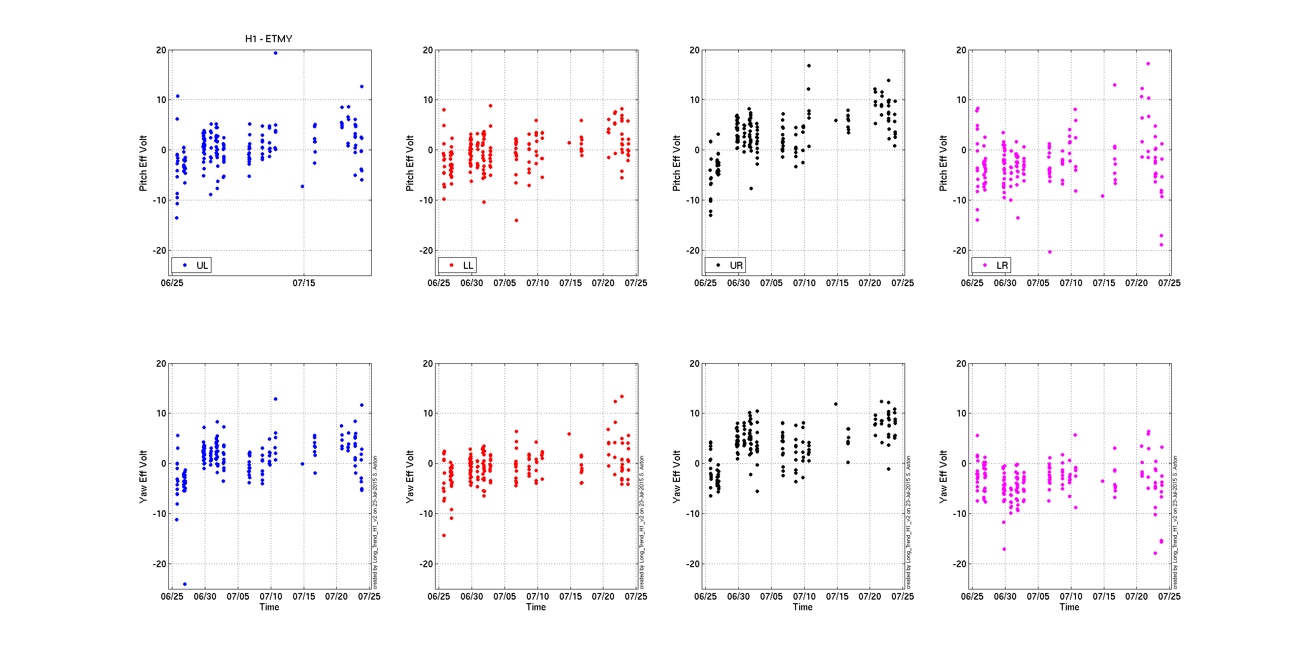
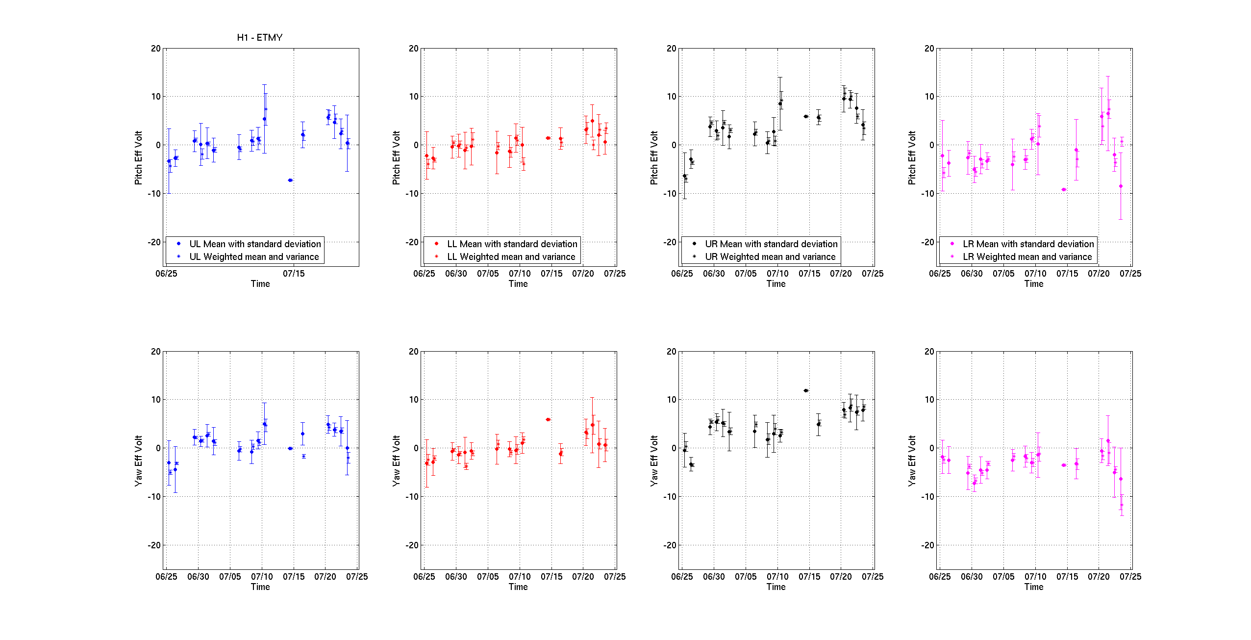
- ETMY charge measurement, Leo, started 10:50AM - assumed done
- ETMX PCAL, Sudarchan, started 9:58, Done 12:57PM
- WP5380 - JeffK, CAL-CS, started 12:54PM, done 12:57PM
- DAQ NDS0 full reboot, Dave - currently in process
Things that are waiting for a window of opportunity:
- WP5349, Filiberto, LVEA Cosmic Ray Detector, started 8:37AM, still work to do if there's a window, ~1 hour
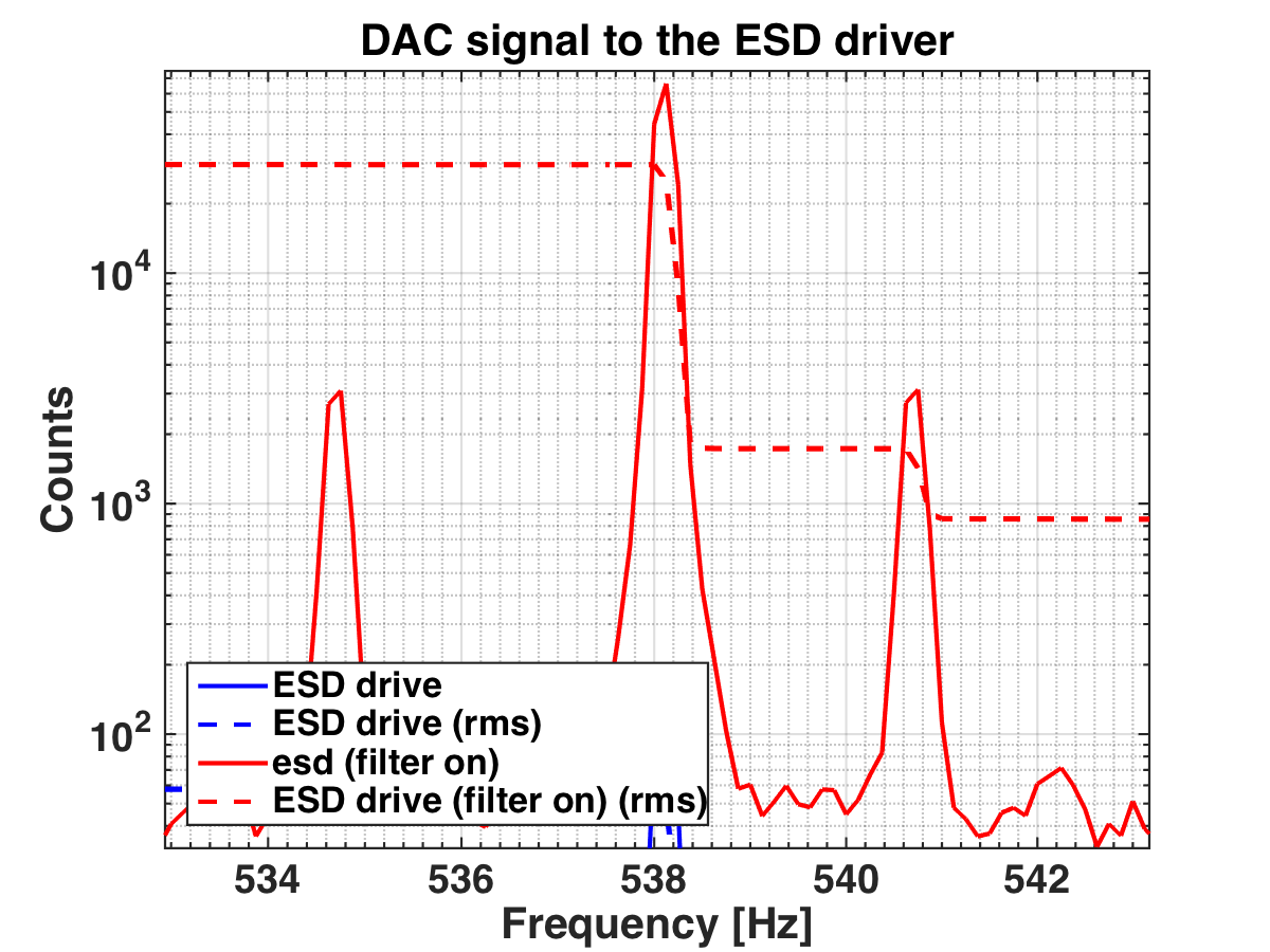
- Low ESD at ETMX, Filiberto, still work to do if there's a window, ~30 minutes