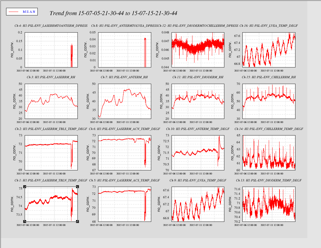
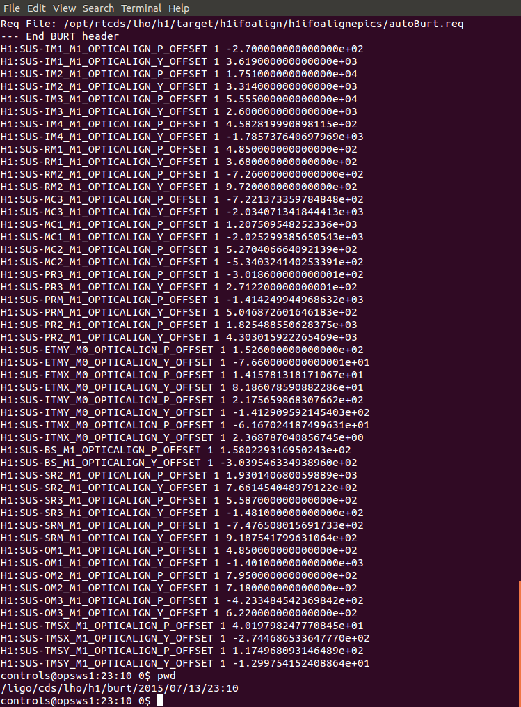
Displaying reports 69001-69020 of 84499.Go to page Start 3447 3448 3449 3450 3451 3452 3453 3454 3455 End
Reports until 16:21, Wednesday 07 January 2015
H1 SUS
travis.sadecki@LIGO.ORG - posted 16:21, Wednesday 07 January 2015 - last comment - 08:17, Thursday 08 January 2015(15928)
Green light photo-subtraction image of ETMy cleaning

WIth Rick's help, we have created a composite image of ETMy before, after, and before-minus-after using Matlab.  Due to saturation of the camera's photodetector in the 'after' photo (we believe due to higher power in the arm), the particles we removed during cleaning appear magenta.  Tomorrow, I hope to do the same with the IR photos. 

Images attached to this report
Comments related to this report
richard.savage@LIGO.ORG - 20:41, Wednesday 07 January 2015 (15932)COC
I think Travis meant to say "before photo" rather than "after photo."

We suspect that the purple color comes from the fact that in the "before" photo the large scatterers were saturating the image at this exposure, as indicated by the bright white fields in the image.  In the "after" photo, we subtract a fair amount of the green light due to the diffuse background scatter which is perhaps brighter due to the higher circulating power resulting from the reduction in losses.  Removing most of the green leaves the red and blue for the saturated scatterers, rendering them purple.
travis.sadecki@LIGO.ORG - 08:17, Thursday 08 January 2015 (15934)

Rick is correct, 'after' should be 'before'.  I also meant that the appearance of more green light scattering in the 'after' photo is likely due to more arm buildup.  Apologies for any confusion induced.

H1 SEI
jim.warner@LIGO.ORG - posted 16:18, Wednesday 07 January 2015 - last comment - 16:30, Wednesday 07 January 2015(15927)
More HAM3 sensor correction measurements

I repeated the measurement from alog 15783, just checking coherence between HAMs 2&3 after we changed HAM3 to look at the right seismometer. Nothing obvious, but I found something interesting. The FIR_IN signals should all be the exactly same at this point, and so should be 100% coherent, between the chambers. The Z signal is not, but the difference is only below 50 mhz, at around .6hz the coherence is almost 100% again. Attached plot shows measurement from the middle of last ni.

Images attached to this report
Comments related to this report
jim.warner@LIGO.ORG - 16:30, Wednesday 07 January 2015 (15929)

Sensor correction is off on HAMs 2&3, I will leave it off on these chambers overnight. I'm also switching the cables on the AA chassis at the rack for STS-A. Will swap back tomorrow morning.

H1 General
jeffrey.bartlett@LIGO.ORG - posted 16:01, Wednesday 07 January 2015 (15925)
Ops Shift Summary
LVEA: Laser Hazard
Observation Bit: Commissioning  

07:30 Karen & Cris – Cleaning in the LVEA
09:05 Aaron & Filiberto – In LVEA cabling work at HAM3 & BS
09:25 Mitch – Working in LVEA West Bay cleanroom
09:43 Hugh – Working in LVEA West Bay area
09:44 Jim & Sebastien – In CER working on HAM2 Electronics
09:53 Andres & TJ – Working on 3IFO Quad storage modifications
10:25 Manny – Cable work around H2 electronics test stand
10:37 Filiberto & Aaron – Finished pulling cables at HAM3/BS. Started terminating these cables
10:50 Sheila – Transition End-X to laser safe  
11:36 Jim & Sebastien – Back in CER working on HAM2 Electronics
11:45 Mitch & Hugh – Out of the LVEA
12:48 Manny – Pulling cables around H2 electronics test stand
14:35 Kyle – End-X to prep for vent
15:16 Kyle – Going to End-Y 
15:28 Kyle – Going back to End-X
H1 PSL
jeffrey.bartlett@LIGO.ORG - posted 15:55, Wednesday 07 January 2015 (15924)
Temp & Dust from PSL
The attached plots are from the period when there were 4 people working in the PSL enclosure on Monday (01/05/15) between 09:00 and 13:00.    
Images attached to this report
H1 PSL
jeffrey.bartlett@LIGO.ORG - posted 15:37, Wednesday 07 January 2015 (15923)
PSL DBB Scans
Took DBB scans of the PSL this afternoon. Plots are posted below
Non-image files attached to this report
H1 CDS
patrick.thomas@LIGO.ORG - posted 12:19, Wednesday 07 January 2015 (15921)
restarted Conlog replication on h1conlog3
I had to restart the replication of the h1conlog database on h1conlog3. The replication thread timed out waiting to acquire a lock. The reported errors are attached. I am investigating.
Non-image files attached to this report
H1 SEI
hugh.radkins@LIGO.ORG - posted 11:56, Wednesday 07 January 2015 (15920)
Two 3IFO BSC ISI Lids Lifted to install 25pin Cable Shorting Blocks

We communicated the major crane movements with the control room commissioners.  No unusual problems.  Two BSCs and five HAMs to go.

H1 ISC
alexan.staley@LIGO.ORG - posted 11:40, Wednesday 07 January 2015 (15919)
Y arm IR low loss point and alignment

Alexa, Thomas, Evan

Conclusion: it appears that we are at a good low loss point for the IR without having to adjust the green QPD offsets.


I locked both the IR and green to the Yarm. The alignment steps I took were the following:

1. I ran the ditherAlign.py script to center the TMSY pointing using the ITM baffle PDs.

2. I had to walk ITMY, ETMY to get high enough flashes in the arm cavity, and then was able to lock the arm on green and engage the green wfs (all 6 DOFs). This brought the green TR buildup to 1.024 cnts.

3. I then locked the IR to the Y arm and engaged the input pointing wfs to PR2, and IM4. This brought the IR TR buildup to 11 cnts.


At this spot, I measured the LSC-ASAIR_A_LF _OUT counts and found Poff = 1304(5) and Pon = 1262(4), this gives an equivalent ETM loss of L = 125(19) ppm. This was calculated following the equations in alog 15874 and 15470. This is a low enough loss spot, and both the IR and green TR buildups are high. I did not have to adjust the QPD offsets (i.e. adjust the green input pointing).

Evan and I were trying to figure out why these results are better than the previous ones in alog 15874. For one the green wfs were not enabled, although the green TR buildup was similar.  We are going to repeat this measurement over a few mornings and see how consistent of a loss we get with this alignment procedure.

H1 SUS
daniel.sigg@LIGO.ORG - posted 09:10, Wednesday 07 January 2015 - last comment - 10:33, Wednesday 07 January 2015(15915)
EX vertical trend

Attached is a plot of EX over the past 30 hours.

Non-image files attached to this report
Comments related to this report
jeffrey.kissel@LIGO.ORG - 10:33, Wednesday 07 January 2015 (15916)
J. Kissel

Daniel's "posted without comment" .pdf reveals a couple of weird things that may incline some to say things like "oh! there's a change there! What's that jump? Doesn't it now look like it's turning up like the other chains?" Don't get caught up in that game. This is the game we've said we'll be playing for weeks. The test mass has still only displaced 5 [um] at most. We need to go more than 100 [um]. Further -- the test mass is *still not free*. I attach transfer functions taken just after this trend was posted. It's still frozen, the TFs look the same as the have since we first started measuring in this year (see LHO aLOG 15878).
Non-image files attached to this comment
LHO General
corey.gray@LIGO.ORG - posted 09:05, Wednesday 07 January 2015 (15914)
Wed Morning Detector Meeting

Most of the meeting focused on discussion for a possible EX vent.

Majority of meeting spent on discussion about OSEM issue at EX, gaps for EQ stops, will decide about EX incursion after SUS meeting.

No Such thing as a "Quick Vent":  Even for a QUICK task in-chamber, EVERY vent has BIG effects (time, contamination, making things worse, etc.)

Will go over Work Permits on Fri

H1 DAQ (CDS)
david.barker@LIGO.ORG - posted 08:30, Wednesday 07 January 2015 (15913)
Strange DAQ second trends behavior

Jim and Dave.

The SUS team brought a DAQ problem to our attention. When viewing minute trends vs second trends for a time period covering yesterday morning/afternoon the two plots did not have the same data. The minute trends are complete, the second trends have data loss. We determined the second trends showed data up to the DAQ restart at 12:36PST and then for part of the last hour. Strangely, only channels from the FE computers showed this data loss, channels from the EDCU showed second trend data over the entire time period. If the second trend time period does not include the DAQ restart, data is shown (i.e. no data is actually lost). Jim determined that this appears to be an NDS and not a dataviewer problem, we are investigating. The work around is to get the second trends in two requests, up to the DAQ shutdown (12:30 PST) and from the DAQ restart (12:40PST).

H1 CDS (DAQ)
david.barker@LIGO.ORG - posted 08:22, Wednesday 07 January 2015 (15911)
CDS model and DAQ restart report, Tuesday 6th January 2015

model restarts logged for Tue 06/Jan/2015
2015_01_06 11:05 h1iopsusauxey
2015_01_06 11:05 h1iopsusey
2015_01_06 11:05 h1susauxey
2015_01_06 11:05 h1susetmy
2015_01_06 11:05 h1sustmsy
2015_01_06 11:58 h1sustmsy
2015_01_06 12:01 h1sustmsx
2015_01_06 12:04 h1susim
2015_01_06 12:08 h1sushtts
2015_01_06 12:10 h1susmc1
2015_01_06 12:12 h1susmc3
2015_01_06 12:14 h1susprm
2015_01_06 12:19 h1susmc2
2015_01_06 12:19 h1suspr2
2015_01_06 12:22 h1sussr2
2015_01_06 12:26 h1sussrm
2015_01_06 12:27 h1susomc

2015_01_06 12:36 h1broadcast0
2015_01_06 12:36 h1dc0
2015_01_06 12:36 h1fw0
2015_01_06 12:36 h1fw1
2015_01_06 12:36 h1nds0
2015_01_06 12:36 h1nds1

2015_01_06 16:11 h1nds1
2015_01_06 16:12 h1nds1
2015_01_06 16:13 h1nds1

X1PLC1 10:01 1/6 2015

X1PLC2 10:01 1/6 2015

X1PLC3 10:01 1/6 2015

Unexpected restarts of h1nds1, possibly related to data requests.

Maintenance Day. FE, DAQ and Beckhoff restarts shown. h1susey and h1susauxey ADC work. New models for non-quad SUS with associated DAQ restart. h1ecatx1 did its usual Tuesday freeze up.

H1 ISC (SUS)
jeffrey.kissel@LIGO.ORG - posted 22:11, Tuesday 06 January 2015 (15910)
BS and PR2 Misaligned
J. Kissel

For the record, I've moved H1 SUS BS and H1 SUS PR2 to MISALIGNED via the guardian, for no other reason that everyone has gone home and the giant projection of the AS port was giving me a seizure from interference flashes thanks to the 6.6 [mag] earthquake in Panama. Please restore at your leisure in the morning.
H1 ISC
evan.hall@LIGO.ORG - posted 21:21, Tuesday 06 January 2015 - last comment - 10:43, Wednesday 07 January 2015(15908)
ISC maintenance

Kiwamu, Alexa, Koji, Evan

MICH dark locking adjustments

For the past few days, it has been difficult to lock MICH on a dark fringe; the velocity of the BS quickly becomes too high. Kiwamu found that turning down the gain from −500 ct/ct to −200 ct/ct during lock acquisition helps this situation; also, once locked, engaging FM2 and FM3 (rather than FM3 and FM6) seems to have a higher probability of success for keeping the Michelson locked.

DRMI ASC degredation

Trying to transition to DRMI_1F_LOCKED_ASC in the ISC_DRMI guardian will blow the lock. This appears to come down to the INP1 and PRC1 loops; the others (PRC2, MICH, SRC1, SRC2) can be engaged by hand just fine. INP1 controls PRM and IM4, and PRC1 controls just PRM. I tried locking with lower gain, with opposite sign, with the PRM M1 bleed-off disengaged, etc., but could not close either loop stably. We'll need to take a deeper look at why these loops no longer work.

BBPD spectrum

With DRMI locked on 1f, Koji and I took an RF spectrum of REFLAIR_B, using the −12 dB coupler on the diplexer (as in LHO#14796). This is the first measurement of the RF spectrum of REFLAIR_B after its modification (LHO#14925).

Comments related to this report
alexan.staley@LIGO.ORG - 08:22, Wednesday 07 January 2015 (15912)

Initial Alignment

We also had some problems running the PRM_ALIGN and SRM_ALIGN via the ISC_DOF guardian. The PRM_ALIGN takes a while to bleed off from the M3 to the M1 stage, and thus to offload. We tried going back to the old version of PRM_ALIGN in which we only feed the wfs back to M1; however, we did not succueed -- a lot of settings had been changed and we could not remember the old configuration; we didn't spend too much time trying to debug. We also ended up aliging SRM by hand which turned out to be faster. We should take some time and look at these scripts since a lot has been changed.

koji.arai@LIGO.ORG - 10:43, Wednesday 07 January 2015 (15917)

BBPD spectrum taken. -12dB coupling has already been compensated. Note that the removal of one of the BBPD preamps reduced the PD gain by ~20dB.

Condition:

H1:LSC-REFLAIR_B_LF_INMON    17000+/-2000
H1:LSC-REFLAIR_B_LF_OUTPUT    17.8+/-0.2 mW
H1:LSC-POPAIR_B_RF18_I_MON    350+/-5
H1:PSL—PERISCOPE_A_DC_POWERMON    10620+/-20
 

Non-image files attached to this comment
H1 SUS
travis.sadecki@LIGO.ORG - posted 16:06, Tuesday 06 January 2015 - last comment - 14:29, Wednesday 07 January 2015(15900)
New photos of ETMy post-cleaning using PCal camera

Using the newly setup PCal capabilites from the Control Room (thanks Dave!), I took some new photos of the ETMy optic post FC cleaning.  Although the IR only image is out of focus (I will take a new one tomorrow after refocusing the camera), the improvement if fairly evident.  The first photo is with green only locked, second photo is with IR only locked.  I used the same camera settings as were used pre-cleaning (F8, ISO 200, 30 sec. exposure, WB-cloudy).

Images attached to this report
Comments related to this report
travis.sadecki@LIGO.ORG - 16:10, Tuesday 06 January 2015 (15903)

For easy comparison, see attached composite photo pre-cleaning.  ETMy is the right hand set of photos.

Images attached to this comment
travis.sadecki@LIGO.ORG - 14:29, Wednesday 07 January 2015 (15922)

As promised, a more in-focus post-cleaning IR locked ETMy image .

Images attached to this comment
H1 COC
evan.hall@LIGO.ORG - posted 16:56, Monday 05 January 2015 - last comment - 11:36, Wednesday 07 January 2015(15874)
Y arm loss

Sheila, Thomas, Elli, Evan

We locked the Y arm in IR, and then turned on WFS loops which feed back to IM4 and PR2 in order to keep the buildup in the arm maximized. We measured the dc counts on ASAIR_A_LF. Then we unlocked the arm and measured ASAIR_A_LF again. The results are as follows:

Using the formula in LHO#15470, the locked and unlocked values of ASAIR give an equivalent loss of 267(31) ppm on ETMY.

To account for the power in the sidebands, we use the modulation depths given in LHO#15674: Γ9 = 0.219(12) and Γ45 = 0.277(16). Then the power in the sidebands is PSB = Poff × (Γ92452)/2 = 81(7) ct. Then using our new value for the power fraction, A2 = (Pon − PSB)/(Poff − PSB), we get an equivalent loss of 286(33) ppm on ETMY, not accounting for mode mismatch.

Comments related to this report
evan.hall@LIGO.ORG - 00:42, Tuesday 06 January 2015 (15880)

We also took loss scans by moving spot on ETMY in a spiral pattern, as in LHO#15476. The sideband power is subtracted here as well. It appears that judicious alignment of the arm may give us lower loss (something like 140 ppm), compared to the number reported above.

In the attached plot, I've masked out data points for which the transmitted power was below 11 ct.

As before, the zero point of the displacement is somewhat arbitrary; we performed the usual initial alignment sequence for the arm (baffle PDs for TMS and the ITM, then maximize the buildup of the green power), but didn't attempt to determine the location of the spots on the test masses.

Non-image files attached to this comment
evan.hall@LIGO.ORG - 11:36, Wednesday 07 January 2015 (15918)

Also note that for the formula in LHO#15470, the physically meaningful solution requires us to take the negative branch of the square root when computing A (so substitute A → −A in this formula).

H1 SUS (ISC)
jeffrey.kissel@LIGO.ORG - posted 18:49, Tuesday 23 December 2014 - last comment - 12:30, Friday 09 January 2015(15809)
H1 SUS ETMY ESD Turned ON, Linearization Force Coefficient ... Explained?
J. Kissel, R. McCarthy

At my request, after seeing that the EY BSC 10 vacuum pressure has dropped below 1e-5 [Torr] (see attached trend), Richard has turned on the H1 SUS ETMY ESD at ~2pm PST. I'm continuing to commission the chain, and will post functionality results shortly. 

Also -- 

I've found the ESD linearization force coefficient (H1:SUS-ETMX_L3_ESDOUTF_LIN_FORCE_COEFF) to be -180000 [ct]. I don't understand from where this number came, and I couldn't find any aLOGs explaining it. I've logged into to LLO, their coefficient is -512000 [ct]. There's no aLOG describing their number either, but I know from conversations with Joe Betz in early December 2014 that he installed this number when the LLO linearization was switched from before the EUL2ESD matrix to after. When before the EUL2ESD matrix the coefficient was -128000 = - 512000/4 so we was accounting for the factor of 0.25 in EUL2ESD matrix. I suspect that -128000 [ct] came from the following simple model of longitudinal force, F_{tot} on the optic as a result of the quadrant's signal voltage, V_{S} and the bias voltage V_{B}, (which we know is incomplete now -- see LLO aLOG 14853):
     F_{tot} = a ( V_{s} - V_{B} )^2
     F_{tot} = a ( V_{s}^2 - 2 V_{s} V_{B} + V_{B}^2)
     F_{lin} = 2 a V_{s} V_{B}
where F_{lin} is the linear term in the force model, and a< is the force coefficient that turns whatever units V_{S} and V_{B} are in ([ct^2] or [V_{DAC}^2] or [V_{ESD}^2]) into longitudinal force on the test mass in [N]. I *think* the quantity (2 a V_{B}) was mistakenly treated as simply (V_{B}) which has always been held at 128000 [ct] (or the equivalent of 390 [V] on the ESD bias pattern) and the scale factor (2 a) was ignored. Or something. But I don't know.

So I try to make sense of these numbers below.

Looking at what was intended (see T1400321) and what was eventually analytically shown (see T1400490), we want the quantity 
       F_{ctrl}
       -------
      2 k V_{B}^2
to be dimensionless, where F_{ctrl} is the force on the optic caused by the ESD. Note that comparing John / Matt / Den's notation against Brett / Joe / my notation, k = a. As written in T1400321, F_{ctrl} was assumed to have units of [N], and V_{B} to have units of [V_{esd}], such that k has units of [ N / (V_{esd}^2) ], and it's the number we all know from John's thesis, k = a = 4.2e-10 [N/V^2]. We now know the number is smaller than that because of the effects of (we think) charge (see, e.g. LHO aLOG 12220, and again LLO aLOG 14853).

In the way that the "force coefficient" has been implemented in the front end code -- as an epics variable that comes into the linearization blockas "Gain_Constant_In,"  (see attached) -- I think the number magically works out to be ... close. As implemented, the linearized quadrant's signal voltage is as shown in Eq. 13 of T1400490, except that the EPICs record, we'll call it G, is actually multiplied in
     V_{S} = V_{C} + V_{B}(1 - sqrt{ 2 [ (F_{ctrl} / V_{B}^2) * G  + 1 + (V_{C}/V_{B}) + (V_{C}/V_{B})^{2} * 1/4 ] )}
Note, that we currently have all of the effective charge voltages set to 0 [ct], so the equation just boils down to the expected
     V_{S} = V_{B}(1 - sqrt{ 2 [ (F_{ctrl} / V_{B}^2) * G  + 1] )}
which means that 
     G == 1 / (2 k) or k = 1 / (2 G)
and has fundamental dimensions of [V_{esd}^2 / N]. So let's take this "force coefficient," G = -512000 [ct], and turn into fundamental units:      
     G = 512000 [ct]             {{LLO}}
         * (20 / 2^18)     [V_{dac} / ct] 
         * 40              [V_{esd} / V_{dac}] 
         * 1 / (V_{B} * a) [(1 / V_{esd}) . (V_{esd}^{2} / N)]
     G = 9.5391e9 [V_{ESD}^2 / N]
   ==>
     k = 5.37e-11 [N/V_{ESD}^2]  {{LLO}}
where I've used V_{B} = 400 [V_{esd}] and the canonical a = 4.2e-10 [N/V_{esd}^2] originally from pg 7 of G0900956. That makes LLO's coefficient  assume the actuation strength is a factor of 8 lower from the canonical number. For the LHO number, 
     G = 180000 [ct]             {{LHO}}
         * (20 / 2^18)     [V_{dac} / ct] 
         * 40              [V_{esd} / V_{dac}] 
         * 1 / (V_{B} * a) [(1 / V_{esd}) . (V_{esd}^{2} / N)]
     G = 3.2697e9 [V_{ESD}^2 / N]
   ==>
     k = 1.53e-10 [N/V_{ESD}^2]  {{LHO}}
Which is within a factor of 3 lower, and if the ESD's as weak as we've measured it to be it may be dead on. So maybe whomever stuck in 180000 is much smarter than I.

For now I leave in 180000 [ct], which corresponds to a force coefficient of a = 1.53e-10 [N/V_{ESD}^2].
Images attached to this report
Comments related to this report
jeffrey.kissel@LIGO.ORG - 15:33, Monday 05 January 2015 (15873)
B. Shapiro, J. Kissel

As usual, two heads are better than one when it comes to these nasty dealings with factors of two (go figure). Brett has caught a subtlety in the front-end implementation that further makes it different from the analytical approach used in T1400321 and T1400490. In summary, we now agree that the LLO and LHO EPICs force coefficients that have been installed are closer to the measured values by a factor of 4, i.e.
G = 512000 [ct] ==> k = 2.0966e-10 [N/V^2]  {{LLO}}
and
G = 180000 [ct] ==> k = 6.1168e-10 [N/V^2]  {{LHO}}
which means, though they still differ from the canonical value (from pg 7 of G0900956)
k = 4.2e-10 [N/V^2]  {{Canonical Model}}
and what we've measured (including charge) (see LHO aLOG 12220, and LLO aLOGs 14853 and 15657)
k = 2e-10 +/- 1.5e-10** [N/V^2] {{Measured}}
they're much closer. 

**I've quickly guesstimated the uncertainty based on the above mentioned measurement aLOGs. IMHO, we still don't have a systematic estimate of the uncertainty because we've measured it so view times, in so many different ways, infrequently, and with the ion pumps still valved in, and each test mass has a different charge mean, charge location, and charge variance.

Here's how the aLOG 15809 math should be corrected: The F_{ctrl} and k = a in the analytic equations is assumed to be for full longitudinal force. However, as implemented in the front end, the longitudinal force F_{ctrl} has already been passed through the EUL2ESD matrix, which splits transforms into quadrant basis force F_{ii}, dividing F_{ctrl} by 4. The EPICs force coefficient, G, should therefore *also* be divided by 4, to preserve the ratio
       F_{ctrl}            F_{ii}
       -------      =   ------------
      2 k V_{B}^2     2 k_{ii} V_{B}^2
inside the analytical linearization algorithm. In other words, as we've physically implemented the ESD, on a quadrant-by-quadrant basis,
       F_{ctrl} = F_{UL} + F_{LL} + F_{UR} + F_{LR}
where
       F_{ii} = k_{ii} (V_{ii} - V_{B})^2
and 
       k_{ii} = k / 4 = a / 4.
As such, the implemented front-end equation
       V_{ii} = V_{B}(1 - sqrt{ 2 [ (F_{ii} / V_{B}^2) * G  + 1] )}
means that
      G == 1 / 2 k_{ii} = 2 / k = 2 / a
and still has the fundamental units of [V_{esd}^2 / N]. So nothing changes about the above conversation from G in [ct] to G in [V_{esd}^2 / N], its simply that the conversion from G to the more well-known analytical quantity k was off by a factor of 4,
     G = 512000 [ct]             {{LLO}}
         * (20 / 2^18)     [V_{dac} / ct] 
         * 40              [V_{esd} / V_{dac}] 
         * 1 / (V_{B} * a) [(1 / V_{esd}) . (V_{esd}^{2} / N)]
     G = 9.5391e9 [V_{ESD}^2 / N]
   ==>
     k = 2.0966e-10 [N/V_{ESD}^2]  {{LLO}}
where I've used V_{B} = 400 [V_{esd}] and the canonical a = 4.2e-10 [N/V_{esd}^2] originally from pg 7 of G0900956. That makes LLO's coefficient assume the actuation strength is a factor of 2 lower from the canonical number, pretty darn close to the measured value and definitely within the uncertainty. For the LHO number, 
     G = 180000 [ct]             {{LHO}}
         * (20 / 2^18)     [V_{dac} / ct] 
         * 40              [V_{esd} / V_{dac}] 
         * 1 / (V_{B} * a) [(1 / V_{esd}) . (V_{esd}^{2} / N)]
     G = 3.2697e9 [V_{ESD}^2 / N]
   ==>
     k = 6.1168e-10 [N/V_{ESD}^2]  {{LHO}}
both of which are closer to the measured value as described above.
jeffrey.kissel@LIGO.ORG - 22:02, Tuesday 06 January 2015 (15905)
N. Smith, (transcribed by J. Kissel)

Nic called and fessed up to being the one who installed the -180000 [ct] force coefficient at LHO. Note -- this coefficient only is installed in ETMX, the ETMY coefficient is still the original dummy coefficient of 1.0 [ct].

He informs me that this number was determined *empirically* -- he drove a line at some frequency, and made sure that the requested input amplitude (driven before the linearization algorithm) was the same as the requested output amplitude (the MASTER_OUT channels) at the that frequency, with the linearization both ON and BYPASSED. He recalls measuring this with a DTT session, not just looking at the MEDM screen (good!). 

Why does this work out to be roughly the right number? Take a look at the front-end equation again:
      V_{ii} = V_{B}(1 - sqrt{ 2 [ (F_{ii} / V_{B}^2) * G  + 1] ) } )
and let's assume Nic was driving V_{ii} at a strength equal and opposite sign to the bias voltage V_{B}. With the linearization OFF / BYPASSED,
      V_{ii} = - V_{B}
Duh. With the linearization in place,
      V_{ii} = - V_{B} = - V_{B} (1 - sqrt{ 2 [ (F_{ii} / V_{B}^2) * G  + 1] ) } )
so we want the quantity 
      (1 - sqrt{ 2 [ (F_{ii} / V_{B}^2) * G  + 1] )} = 1
which only happens if 
      (F_{ii} / V_{B}^2) * G = 1.
If Nic wants to create a force close to the maximum, it needs to be close to the maximum of 
      F_{ii,max} = 2 k_{ii} V_{B}^2, 
which makes
      2 k_{ii} * G = 1
or
      G = 1 / (2 k_{ii}) = 2 / k
which is the same result as in LHO aLOG 15873. Granted, it's late and I've waved my hands a bit, but this is me trying to justify why it feels like it makes sense, at least within the "factor of two-ish" discrepancy between the canonical value and the accepted measurements of the right number. 
jeffrey.kissel@LIGO.ORG - 12:30, Friday 09 January 2015 (15966)
I've summarized this exploration of Linearization Science in G1500036.
Displaying reports 69001-69020 of 84499.Go to page Start 3447 3448 3449 3450 3451 3452 3453 3454 3455 End