Dave, Jonathan, Greg, Daniel
Last Tuesday (June 23rd 2015 between 12:30 and 15:50 PDT), Dave and I took a GPS time output signal from one of the rear BNC ports on a Timing IRIG-B module in EY. We temporarily fed the signal into the 16kHz rack microphone channel (see https://alog.ligo-wa.caltech.edu/aLOG/index.php?callRep=19299):
H1:PEM-EY_MIC_VEA_MINUSY_DQ
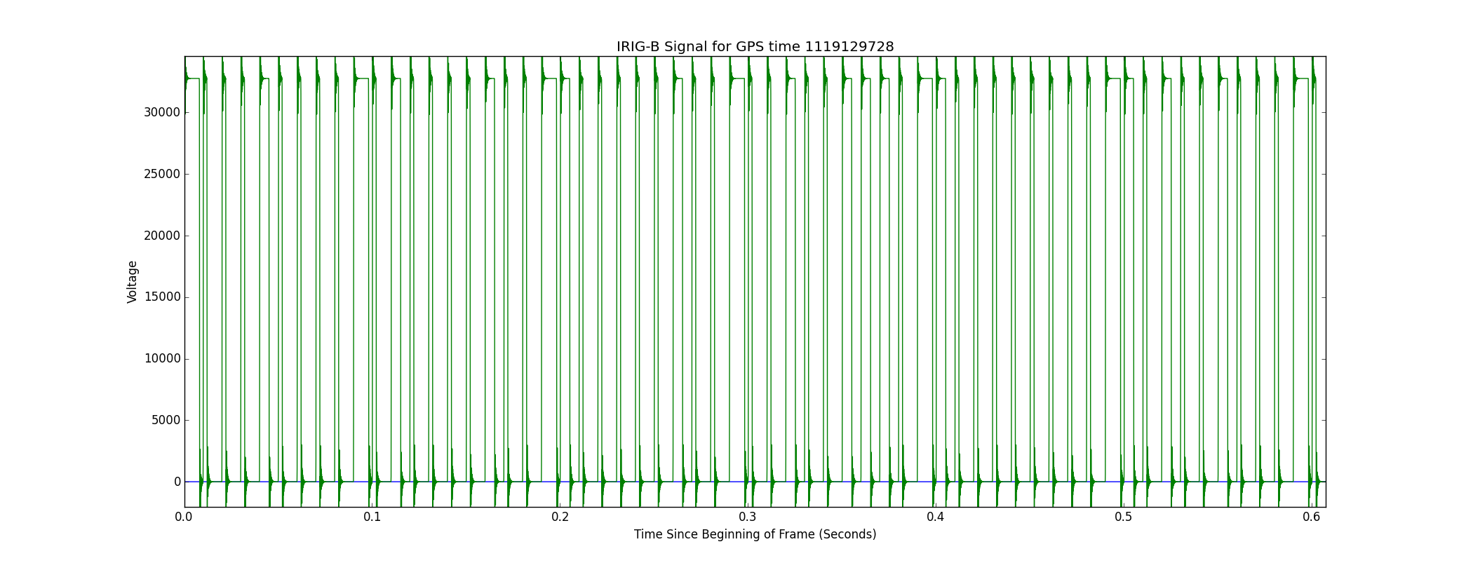
in order to record the signal in frame. Dave then found the frame file, and Jonathan extracted the first second of the H1:PEM-EY_MIC_VEA_MINUSY_DQ channel (each raw frame file has 64 seconds of data and is named according to the first second) into both text and binary formats. I then read the binary file (a bunch of 32 bit floats) using Julia, and compared the resulting array to the NDS-generated text file to confirm that the values were the same. I plotted the signal and read it twice, recording the long/short/control pulse sequence each time to make sure I'd read it correctly. I then decoded it using the IRIG-B signal spec. Finally, I compared it to the ostensible recording time, as indicated by the filename. c00010000c010000100c100000100c001001110c100000000c101001000c0
The signal as I recorded it (control = c, short = 0, long = 1) along with the decoded time; it matches the GPS time of the frame (which is 16 seconds later than the UTC time of the frame). A plot of the data is attached.
c00010000c010000100c100000100c001001110c100000000c101001000c0
0001 000 0100 010 1000 01 0010 1110 10 1010 1000 8
8s 22m 21h 174d 15y
Which corresponds to June 23rd, 2015 at 21:22:08 GPS time.
The GPS time (from the name of the frame, as recorded in the attached text file dump) is 1119129728.
This corresponds to Jun 23, 2015, 21:21:52, which is 16s early, as expected, due to the 16 current leap seconds.
It seems, then, that the IRIG-B Timing Module's signal isn't misaligned with the DAQ (at least not catastrophically).