Sudarshan, Kiwamu, Darkhan,
Abstract
According to the PCALY line at 540.7 Hz, the DARM cavity pole frequency dropped by roughly 7 Hz from the 17 W configuration to the 23 W (alog 18923). The frequency remained constant after the power increment to 23 W. This certainly impacts on the GDS and CAL-CS calibration by 2 % or so above 350 Hz.
Method
Today we've extracted CAL-DELTAL data from ER7 (June 3 - June 8) to track cavity pole frequency shift in this period. The portion of data that can be used are only then DARM had stable lock, so for our calculation we've used a filtered data taking only data at GPS_TIME when guardian flag was > 501.
From an FFT at a single frequency it is possible to obtain DARM gain and the cavity pole frequency from the phase of the DARM line at a particular frequency at which the drive phase is known or not changing. Since the phase of the resultant FFT does not depend on the optical gain but the cavity pole, looking at the phase essentially gives us information about the cavity pole (see for example alog 18436). However we do not know the phase offset due to time-delay and perhaps for some uncompensated filter. We've decided to focus on cavity pole frequency fluctuations (Delta f_p), rather than trying to find actual cavity pole. In our calculations we have assumed that the change in phase come entirely from cavity pole frequency fluctuations.
The phase of the DARM optical plant can be written as
phi = arctan(- f / f_p),
where f is the Pcal line frequency;
f_p - the cavity pole frequency.
Since this equation does not include any dependence on optical gain, the technique we use, according to our knowledge, the measured value of phi does not get disturbed by the change of the optical gain. Introducing a first order perturbation in f_p, one can linearize the above equation to the following:
f_p^2 + f^2
(Delta f_p) = ------------- (Delta phi)
f
An advantage of using this linearized form is that we don't have to do an absolute calibation of the cavity pole frequency since it focues on fluctuations rather than the absolute values.
Results
Using f_p = 355 Hz, the frequency of the cavity pole measured at the particular time (see alog 18420), and f = 540.7 Hz (Pcal EY line freq.), we can write Delta f_p as
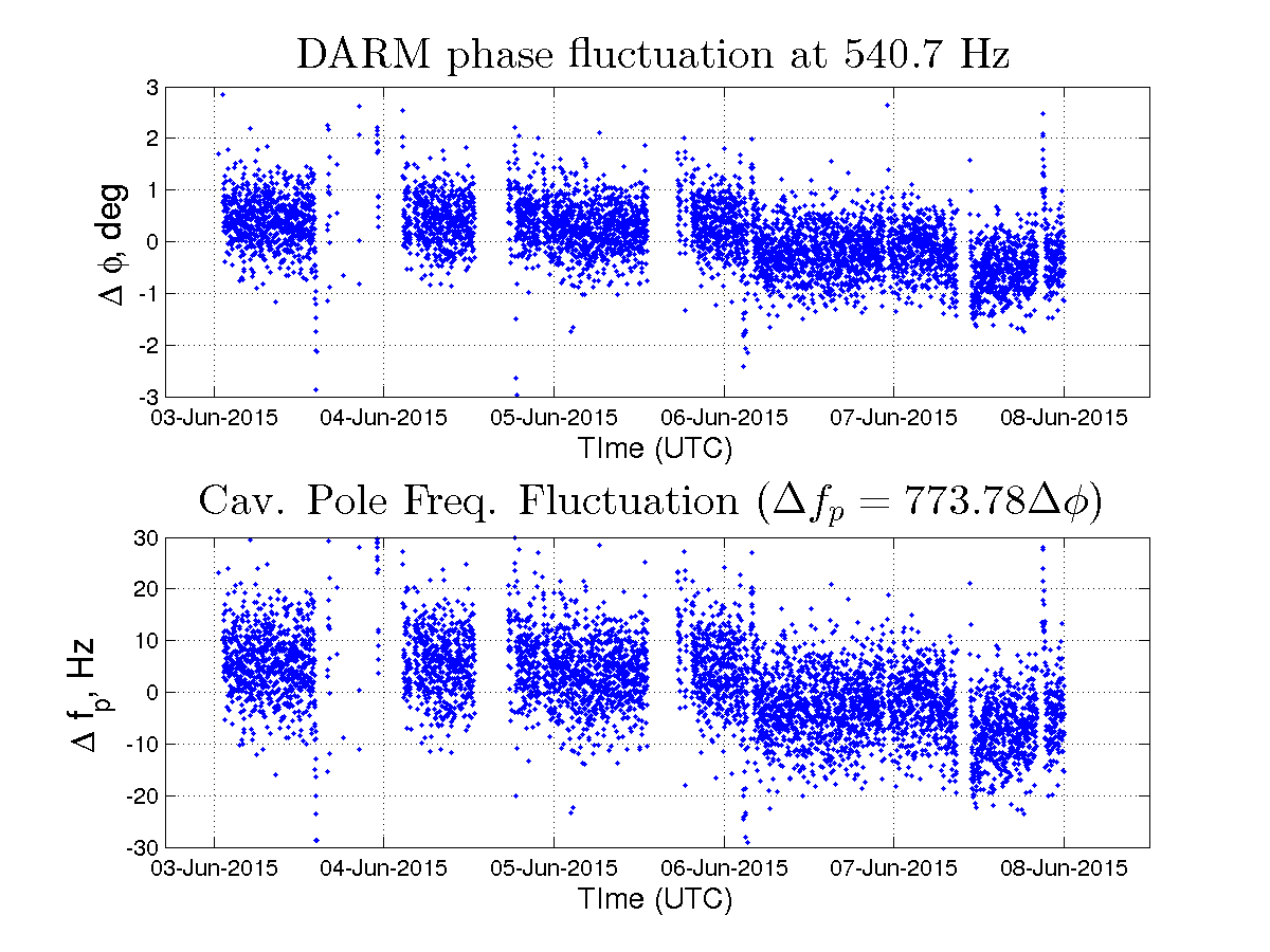
Delta f_p = 773.78 * (Delta phi)
Delta f_p trend based on ER7 data is given in the attached plot: "Delta phi" (in degrees) in the upper subplot and "Delta f_p" (in Hz) in the lower subplot.
Judging by overall trend in Delta f_p we can say that the cavity pole frequency dropped to about 7 Hz after June 6, 3:00 UTC, this correspond to a time when PSL power was changed from 17 W to 23 W (see lho alog 18923, [WP] 5252)
Delta phi also show fast fluctuations of about +/-3 degrees, and right now we do not know the reason that causes this "fuzzyness" of the measured phase.
Filtered channel data was saved into:
aligocalibration/trunk/Runs/ER7/H1/Measurements/PCAL_TRENDS/H1-calib_1117324816-1117670416_501above.txt (@ r737)
Scripts and results were saved into:
aligocalibration/trunk/Runs/ER7/H1/Scripts/PCAL_TRENDS (@ r736)