The quad matlab model generate_QUAD_Model_Production.m script has 3 new features:
1) reading in live damping filters
2) reading customized parameter files for the suspensions
3) building models with fiber violin modes based on the measured frequencies and Qs
svn up the following directory: ../SusSVN/sus/trunk/QUAD/Common/MatlabTools/QuadModel_Production/
Here is an example of how to build a model with all 3 features:
quadModel = generate_QUAD_Model_Production(frequency_vector,'h1etmy',[],0,true,'liveh1etmy',0,0,true,8);
* frequency_vector is some frequency vector you specify.
* 'h1etmy' is the customized H1 ETMY parameter file (quadopt_fiber is the general quad file). All other quads have parameter files now too, but h1etmy is the only unique one at this point.
* true (the first one) says you want damping
* 'liveh1etmy' says you want live filters from H1 ETMY. The 'live' prefix is what triggers the flag to read live filters. The code imports the filters from 5 minutes in the past, to allow for some latency.
* true (the second one) says you want violin modes
* 8 says you want the first 8 violin modes in the model (2 is the default if not specified)
The h1etmy.m parameter file includes the measured mode frequencies for the first 8 violin modes at the bottom of the file. More can be added as desired. There is also a place holder for the measured Qs, but I am not aware of any measured values. The violin mode script (called by the generate script) will incorporate any measured values found in the parameter file. It will use modeled values for those that are not specified.
I'll leave the testing of the live filter reading to the people at the sites, since this is harder to do off site. Please let me know if something doesn't work properly. I've only gone as far as checking that it compiles (on my laptop) and that the closed loop system is stable.
The generate script has instructions for setting up your computer to run the live filters. This text is copied here:
> Follow noise budget SVN checkout instructions here
https://awiki.ligo-wa.caltech.edu/aLIGO/NoiseBudget
Checkout the following addpath paths:
svnDir = '../NbSVN/aligonoisebudget/trunk/' (the '..' must be the same as for the SusSVN, e.g. /ligo/svncommon/)
addpath(genpath([svnDir 'Externals/SimulinkNb/']))
addpath([svnDir 'Common/Utils/NoiseModel/'])
addpath([svnDir 'Common/Utils/'])
> Follow NDS2 install instructions here
https://wiki.ligo.org/viewauth/RemoteAccess
Matlab should be pointed to this version of liveparts.m:
../NbSVN/aligonoisebudget/trunk/Externals/SimulinkNb/SimulinkNb/liveParts.m

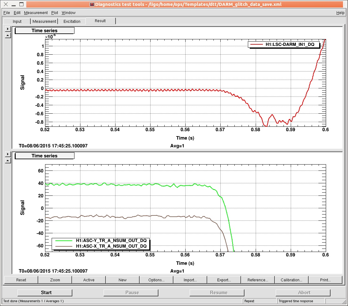

I went out to watch the cleaning earlier in the day and returned after work had finished to reproduce some of the cleaning activities. I was on the phone with the operator who monitored DARM for glitches. I found that tapping the beam tube with metal like the water/vacuum nozzles produced large glitches, but brushing with the brushes did not. I found that the softer the instrument, the harder it was to make glitches. I was never able to make glitches with my fist, but there was nearly a one-to-one coincidence with metal taps. All glitches, according to Jim, the operator, were broad band and a couple of orders of magnitude above background. I had to wait quite a time for the spectrum to settle down before tapping again. The glitches were like delta functions, not like scattering shelves. There did not seem to be a difference between locations at a baffle and half way between baffles.
I suggested to Bubba and John that we might make fewer glitches if there was a polymer guard on the nozzles.
I guess that the important quantities for freeing metal oxide particles are either acceleration or change in curvature of the beam tube. The difference between soft and hard "hammers" is consistent with both of these hypotheses. I think that it is important to estimate the inter-site coincidence rate and propose that I mount an accelerometer and a shaker on the tube to study glitching as a function of frequency and amplitude. I suspect that there is a soft threshold in curvature change or acceleration, and that this will be fairly constant with time since the oxide layers should no longer be growing.