Sudarshan, Duncan, Branson, Andrew, Michael T, Greg, Dave:
I got a lot further in installing the GRB alert system at LHO. It now runs, but fails after a couple of minutes. Here is a summary of the install:
LHO and LLO sysadmins decided to run the GRB code on the front end script machine (Ubuntu12). At LHO it is called h1fescript0
I requested a Robot GRID Cert for this machine, Branson very quickly issued the cert for GraceDB queries last Friday
Following Duncan's and the GraceDB install instructions, I was able to install the python-ligo-gracedb module. The initial install failed, Michael resolved this, I was using the Debian Squeezy repository (which uses python2.6) rather than Wheezy which uses python2.7.
Greg told us how to install the GRID cert on the machine and setup the environment variable so the program could find it.
I found a bug in the code for the lookback, it appears the start,stop times were reversed in the arguments to client.events().
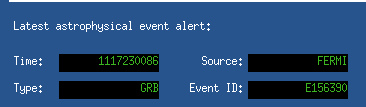
For testing, I saw that a GRB event had happened within the past 10 hours, so I ran the program with a 10 hour lookback. It found the event and posted it to EPICS (see attachement)
But afer running for several minutes, it stopped running with an error. This is reproducible.
controls@h1fescript0:scripts 0$ python ext_alert.py run -l 36000
Traceback (most recent call last):
File "ext_alert.py", line 396, in
events = list(client.events('External %d.. %d' % (start, now)))
File "/usr/lib/python2.7/dist-packages/ligo/gracedb/rest.py", line 450, in events
response = self.get(uri).json()
File "/usr/lib/python2.7/dist-packages/ligo/gracedb/rest.py", line 212, in get
return self.request("GET", url, headers=headers)
File "/usr/lib/python2.7/dist-packages/ligo/gracedb/rest.py", line 325, in request
return GsiRest.request(self, method, *args, **kwargs)
File "/usr/lib/python2.7/dist-packages/ligo/gracedb/rest.py", line 200, in request
conn.request(method, url, body, headers or {})
File "/usr/lib/python2.7/httplib.py", line 958, in request
self._send_request(method, url, body, headers)
File "/usr/lib/python2.7/httplib.py", line 992, in _send_request
self.endheaders(body)
File "/usr/lib/python2.7/httplib.py", line 954, in endheaders
self._send_output(message_body)
File "/usr/lib/python2.7/httplib.py", line 814, in _send_output
self.send(msg)
File "/usr/lib/python2.7/httplib.py", line 776, in send
self.connect()
File "/usr/lib/python2.7/httplib.py", line 1157, in connect
self.timeout, self.source_address)
File "/usr/lib/python2.7/socket.py", line 571, in create_connection
raise err
socket.error: [Errno 110] Connection timed out