After we got back to low noise (yay!), I spent a few hours working on the OMC. The salient points are:
-
The length dither frequency has been changed to 4100Hz. I made a coarse scan of dither frequencies, this setting minimized the upconversion of OMC length drive --> OMC transmitted light.
-
Various low-passes have been removed from the length path to simplify loop shape, they have been replaced by a bandpass before the dither demodulation (recommended by Keita some time ago)
-
The ASC dither has been recommissioned. This is not yet integrated into the Guardian.
OMC Length Dither Frequency
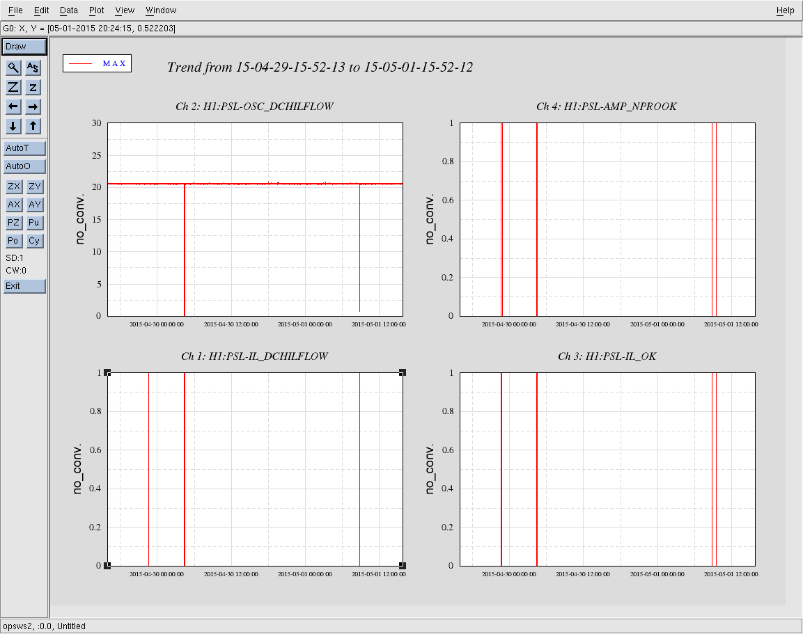
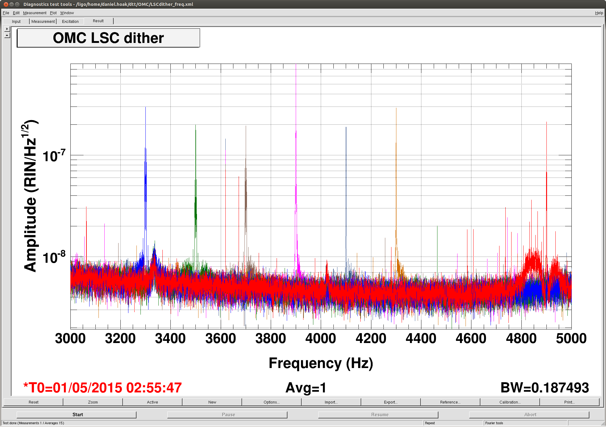
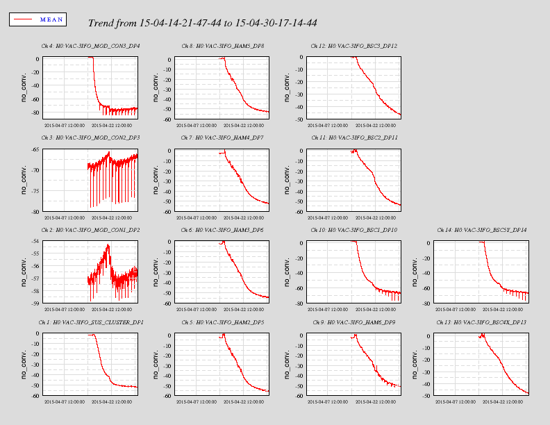
Koji recommended that the dither frequency be changed to move away from some excess noise he suspected was polluting the error signal. I scanned the dither frequency from 3300Hz to 4900Hz in 200Hz steps. Sure enough, there is a bump of excess noise around 3335Hz that had been coupling to the length error signal when the frequency was set to 3300Hz.
The first plot attached shows the sidebands and excess noise structure for these different frequencies (the channel plotted is the OMC-DCPD RIN). It's not a very convincing plot, but setting the frequency at 4100Hz gave us the cleanest spectrum. (I will post more convincing measurements later.) It would be good to do a finer scan in the future. I think the dither frequency at L1 is currently 4800Hz.
As the dither frequency was scanned I monitored an excitation at 12Hz into PZT2, this was necessary to keep track of which quadrature of the demodulated dither signal was the best measure of the length of the cavity. Here's the data keeping track of how the length excitation rotated from COS to SIN as the dither frequency was changed:
|
Dither Frequency |
COS/EXC (mag, dB) |
COS/EXC (phase, deg) |
SIN/EXC (mag, dB) |
SIN/EXC (phase, deg) |
Demod Phase to lock the servo |
|
3300 |
-27 |
65 |
-27 |
-110 |
90 |
|
3500 |
-26 |
85 |
-61 |
-40 |
90 |
|
3700 |
-27 |
65 |
-27 |
65 |
90 |
|
3900 |
-35 |
37 |
-25 |
37 |
90 |
|
4100 |
-35 |
-105 |
-25 |
80 |
0 |
|
4300 |
-26 |
-125 |
-28 |
55 |
0 |
|
4500 |
-25 |
-95 |
-50 |
no coherence |
-90 |
|
4700 |
-25 |
-105 |
-25 |
-100 |
-90 |
|
4900 |
-50 |
no coherence |
-25 |
-70 |
180 |
Since the phase was changing it was necessary to adjust the demod phase to put the right quadrature into the length loop. (Why is the phase changing? Is it from a digital delay, or a mechanical resonance in the PZT?)
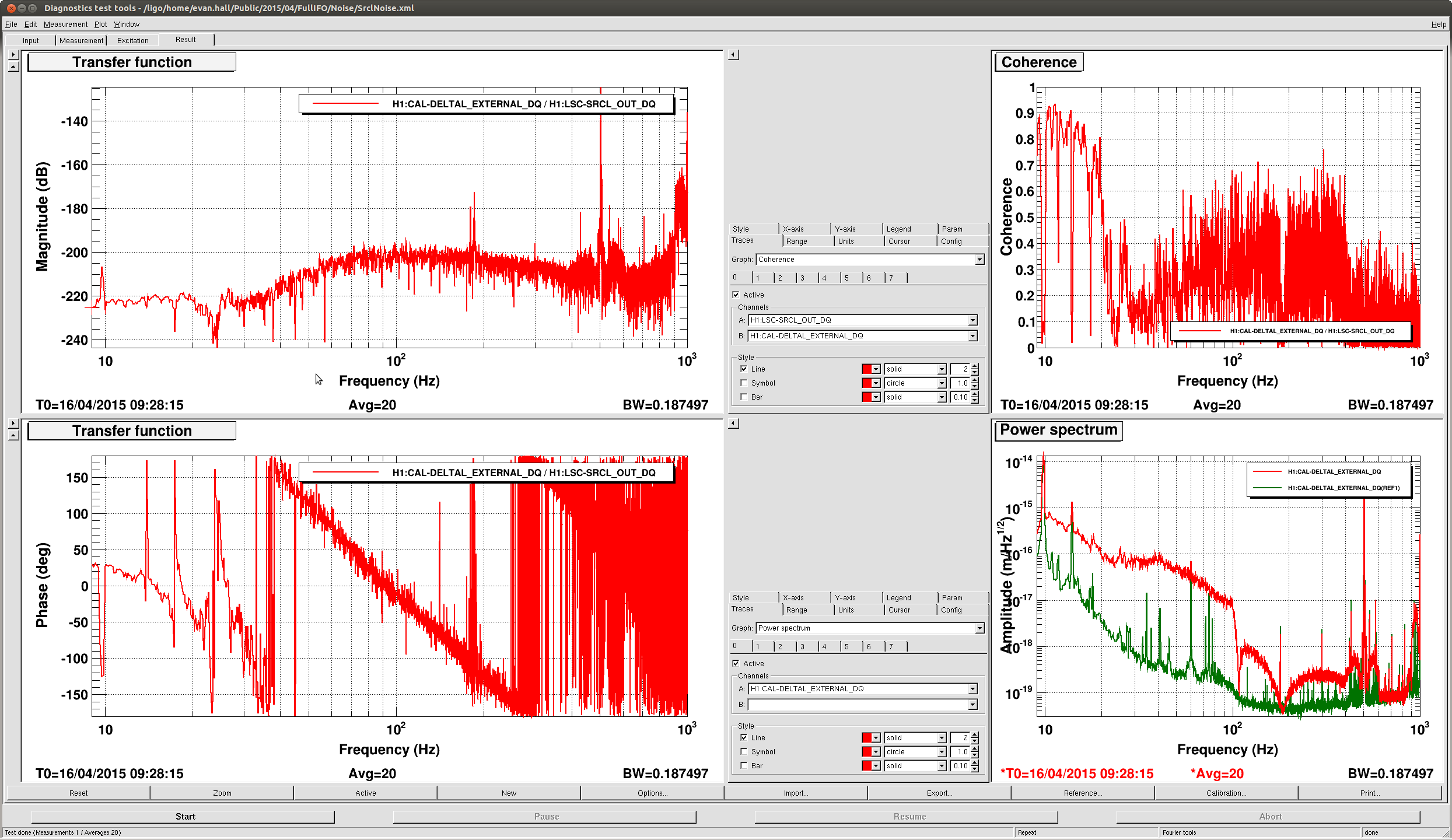
OMC Length Loop Shape
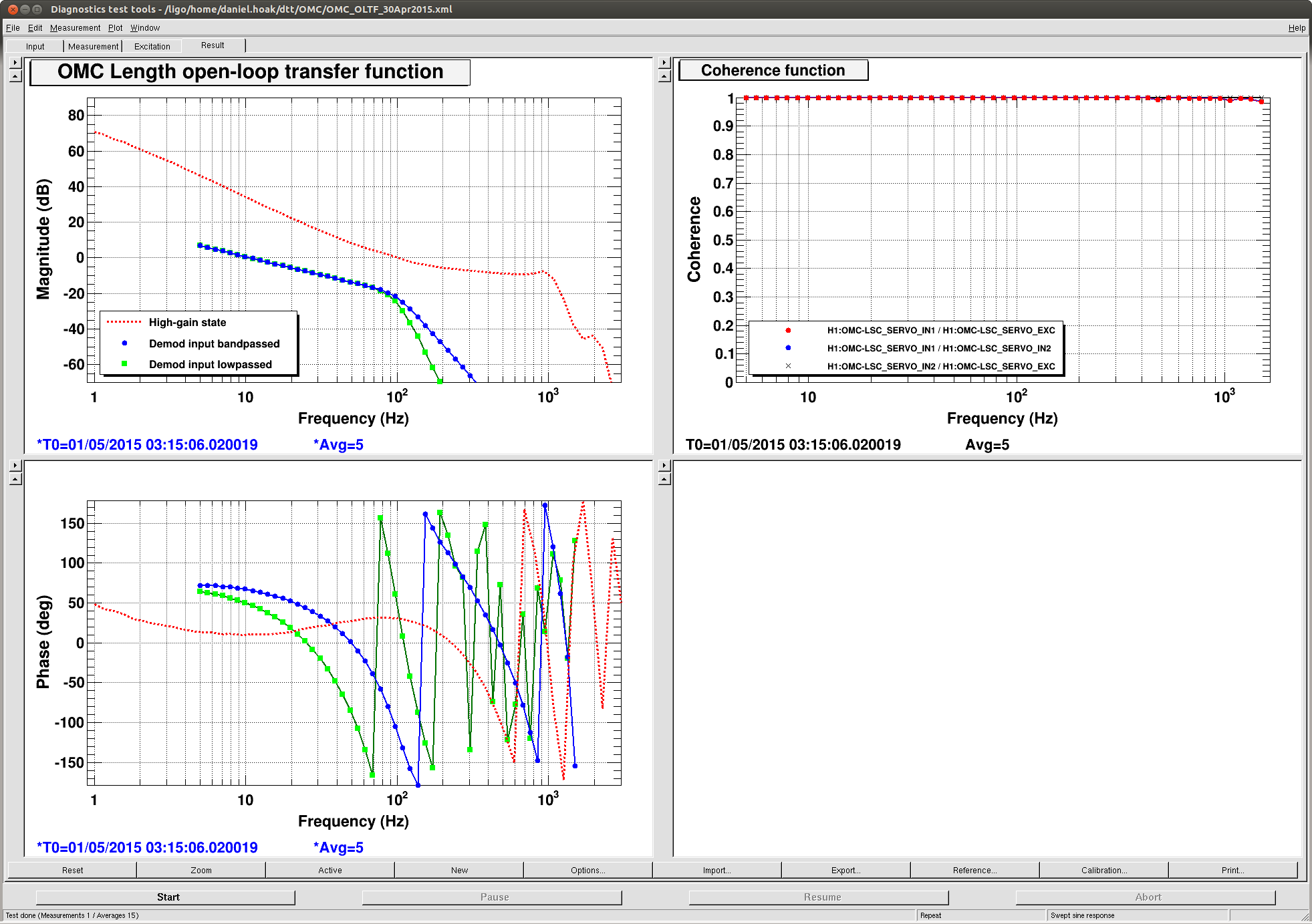
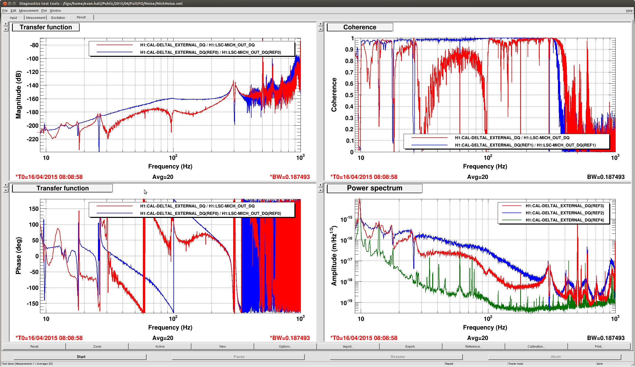
With the dither frequency set I inserted a 200Hz-wide bandpass around the dither frequency before the demodulation, and removed all of the ELPs and butterworth LPs that we had been using to suppress demodulated junk from getting into the control signal. An OLTF is attached (Fig 2), the UGF is 10Hz -- still a little high, from Koji's measurement -- and there is 67deg of phase margin. (In the legend, the green trace is the demod input highpassed, not lowpassed.)
The correct filters to use in the OMC length loop path are now:
LSC-PD_IN: FM2,5 (butterfly bandstop, 200Hz bandpass around 4100Hz)
LSC-X_COS, LSC-X_SIN: FM2 (double ELP for notch at 4100Hz)
LSC-SERVO: FM1, 2, 6, 8, 10 (boost, integrator, anti-dewhites and calibration constants)
This will give you a loop that looks like the blue trace in Fig 2. The gain of the servo is still set to 10.
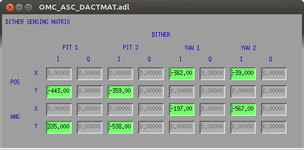
OMC Alignment Dither
We've changed the alignment dither frequencies to [1675.1, 1700.1, 1725.1, 1750.1] Hz, but we never re-commissioned the loops. Today I spent quite a while trying to measure a dither sensing matrix with excitations into the QPD loops at 1.1Hz. This never produced an answer that worked upon inverting. Kiwamu mentions that things might be complicated by the actuation on the OMC SUS, and AC excitations could be exciting other DOFs than what we want to measure.
In the end I measured a sensing matrix at DC, with offsets into the QPD loops, inverted and got something that worked. We can engage the dither loops now, but I recommend ramping down the QPD loops (with the master gain slider), switching to the dither input, and then turning up the gain. It's probably good to keep the gain low, at 0.4, this gives a response to DC offsets of ~10 seconds. I didn't have a chance to measure the sensing noise to estimate the useful bandwidth. This has not been added to the OMC Guardian.


Andy, all: yep we had one calibration sweep in place during the first lock, apologies. From now on, we'll only allow for hardware injections when the intent bit is set.
Let us know if there is an interval you require (e.g. 2048s?) betwen injections.
We lost lock ~20 minutes ago. I've reset the intent bit. Looks like a rung up violin mode on ITMY. Jeff is working on damping it.