Dan, Kiwamu, Evan
Summary
Tonight we worked on getting the interferometer back to its low-noise state. We are stable at 10 W, but there is some instability at higher powers.
Details
ITM steering
First, at 3 W we manually steered the ITMs to a good recycling gain (38 W/W), and then updated the TMS QPD offsets. We also locked the arms in green, adjusted the green QPD offsets for maximum buildup, and then updated the ITM camera references. Then we re-enabled the ITM loops in the guardian. This allowed us to power up all the way to 21 W without significant degredation of the recycling gain.
After that, we were able to consistently engage the ASC with the guardian.
Power-up issues
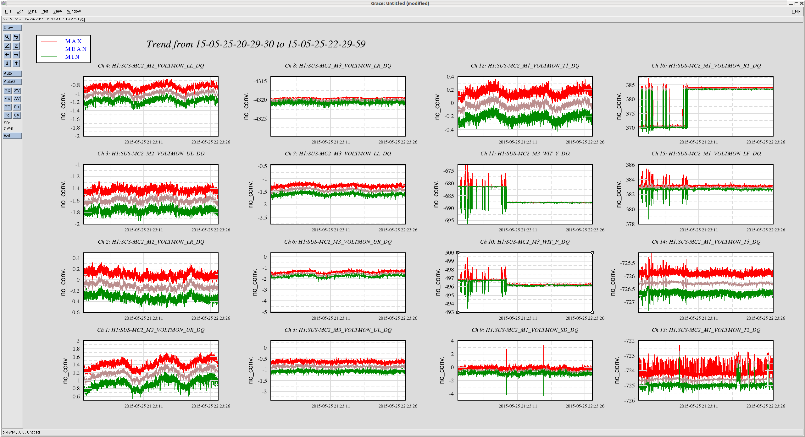
However, we found that at 21 W the interferomter suddenly unlocks in a matter of minutes. There seems to be no instability in the arm or sideband buildups before the lockloss. We looked at OMC DCPD signals for signs of PI, but we did not see anything ringing up during any of our short high-power locks. Some times to look at are 02:29:50, 02:59:50, 04:57:30, 06:55:00, all 2015-05-26 UTC. But any of the other 21 W locklosses in the past 12 hours follow this pattern.
We measured the OLTFs of PRCL, MICH, SRCL, and DARM before and after powering up, but they all look fine and did not change with power. For CARM, we start at 3 W with a UGF of 14 kHz with 47° of phase. Then during power-up, the electronic gain is automatically adjusted to compensate for the increased optical gain. The algorithm for this was shooting a little high, so after power-up the UGF was more like 27 kHz with 30° of phase. This is probably fine, but we adjusted the algorithm anyway, so that the UGF is placed at 19 kHz, with 45° of phase. Anyway, this did not solve the lockloss issue.
We also tried locking at some lower powers. At 15 W the interferometer lasted for about 15 minutes before unlocking. At 10 W, the lock time seems to be indefinite (at least 90 minutes).
DARM crossover
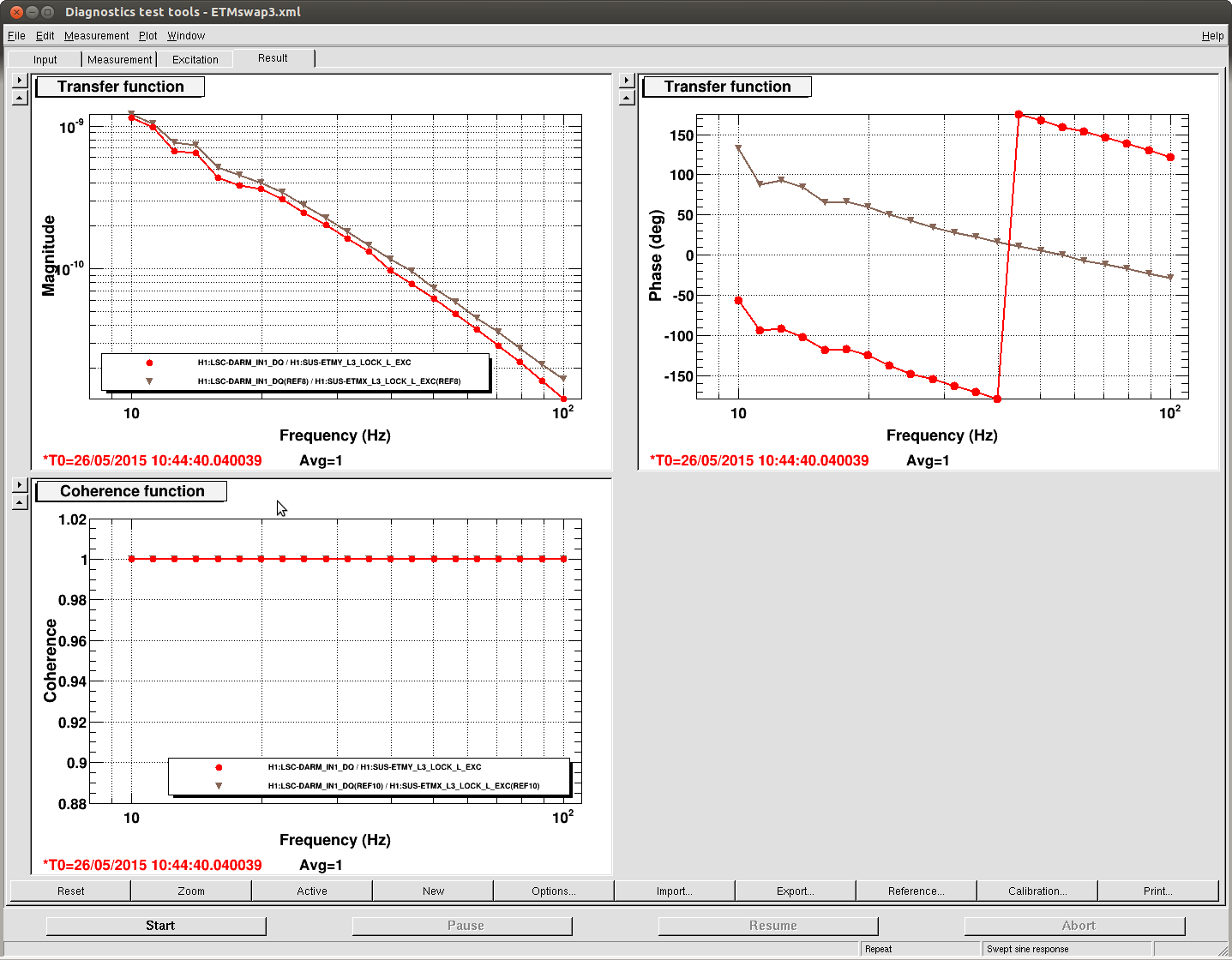
Using FM9 in ETMY L1 LOCK L (zero at 2 Hz, pole at 5 Hz), we were able to push the L1 crossover from <1 Hz to 1.7 Hz by adjusting the filter gain from 0.16 to 0.31. Measurement attached, showing before and after. This is not included in the guardian. By pushing up the crossover, the rms drive to L2 decreases from >10000 ct to about 6000 ct or so.
Other
For the record, we did not notice any kicks to the yaw of IMC REFL tonight.


New Damping Settings for Bounce, Roll, Violin modes
Over the weekend we were able to re-commission the damping of the bounce, roll and violin modes. The bounce & violin damping settings have been propagated to the ISC_LOCK guardian, and should be stable (maybe). The roll mode settings have already changed once over the weekend, so I'll list what's been working, but your mileage may vary.
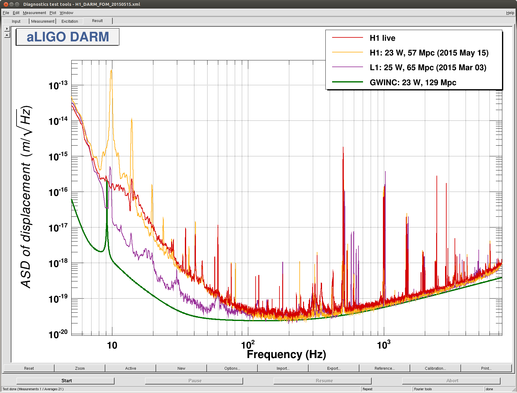
The attached spectrum (for 10W, low-noise ESD, *not calibrated*, no LSC FF, so don't study it too closely) shows the mode-damping progress. Note this was before the 2.4k and 2.8k violin harmonics were damped.
Bounce modes:
After struggling to apply very narrow band-pass filters a la Jeff's approach from alog:18483, we reverted to the method of very broad band-passes. These are loaded as FM3 in the DARM_DAMP_V filter banks. The frequencies follow those listed by Sheila in alog:18440 (we confirmed these frequencies were correct through the course of our damping exercise).
| ETMY | ETMX | ITMY | ITMX | |
| Frequency [Hz] | 9.73 | 9.77 | 9.81 | 9.85 |
| Filters | FM1 (+60deg), FM3 | FM3 | FM1 (+60deg), FM3, FM6 (+30deg) | FM2 (-60deg), FM3 |
| Gain | -0.3 | -0.5 | +1.0 | +0.3 |
The real key to squashing the bounce mode peak was to work out the damping settings for ETMX and ITMY (the optics which couple bounce --> longitudinal motion the least). The extra 30deg of phase for ITMY turned out to be important.
Roll modes:
We were able to damp the ITMX roll mode, thus breaking the unpaired set of frequencies for roll modes and assigning each peak to an optic. The ITMX roll mode wasn't rung up this weekend, so we didn't have a chance to work out damping settings. The sign for damping the ETMY roll mode flipped between Sunday and Monday night, otherwise these damping settings were pretty stable.
For all the TMs the FM4 filter is a broad band-pass from 13.5 to 14.5Hz.
| ETMY | ETMX | ITMY | ITMX | |
| Frequency [Hz] | 13.816 | 13.889 | 13.930 | 13.978 |
| Filters | FM3 (-100dB), FM4, FM6 (+30deg) | FM3 (-100dB), FM4 | FM3 (-100dB), FM4 | ?? |
| Gain | -20 | +600 | -80 | ?? |
The roll mode is rung up after every lockloss (usually it's ETMY), so these settings need to be manually applied before the transition to DC readout. The gains listed in the table above are the "high-gain" damping state, if the mode is very rung up you need to start at a lower gain setting or you might saturate the M0 stage.
Violin Modes
Recall that violin mode frequencies and their associated test masses were given in alogs 17365, 17502, and 17610.
All the identified modes are well-damped and have been enabled in the Guardian code, with the exception of ITMX. Despite many attempts I haven't been able to actuate on the ITMX modes at all. Before the realignment/recycling gain work the ITMX modes damped very easily, now I can't find a DOF (longitude, pitch, or yaw) or a phase setting to move the modes either up or down. It's hard to believe the L2 stage of ITMX isn't working, so we're not sure what the problem is. Maybe we just need more patience.
The complete set of violin mode damping settings is too large to list here; the various filters and gains are recorded in the guardian code. Some modes require a specific filter to get the right phase, others can be grouped together with broad band-pass filters without much trouble. In particular, ITMY requires separate filters for each mode, it's very difficult to construct a broad band-pass that catches more than one mode with the correct phase. We need to add more filter banks to the L2 DAMP section of the quad models if we want to squash the violin modes and their harmonics.
We did identify some new modes -- since we started feeding DARM back to the ETMY L2 stage we rang up the 4th, 5th, and 6th harmonics of that optic. These modes were easily damped and have been notched in the actuation path. The specific frequencies and damping settings were:
2424.38, 2427.25 Hz: Use FM6 of ETMY L2 DAMP MODE1, +60deg of phase, +100dB, gain=+20k, longitudinal direction
2878.7, 2882.5 Hz: Use FM6 of MODE2, no phase, gain=+10k, longitudinal direction
3330.6 Hz: Use FM5 of MODE3, -60deg of phase, gain=+20k, longitudinal direction
3335.7 Hz: Use FM6 of MODE3, no phase, gain=+20k, longitudinal direction
Keita, Sheila
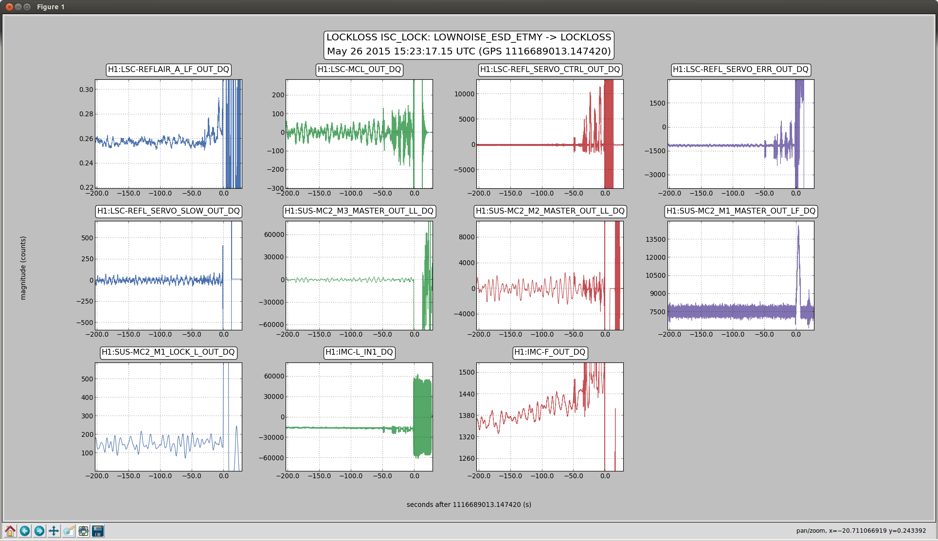
In three of last night's 10 Watt locklosses, as well at the 15 Watt lockloss, the CARM loop dropped first, when IMC-F reached something around +/- 1440 kHz (the first screen shot attached is typical, 2015-05-26 15:23:17, 13:228:28, 12:10:29, and 7:38:16 at 15 Watts). Now that Jeff has fixed the model and we are using tidal again, this type of lockloss has not been bothering us tonight.
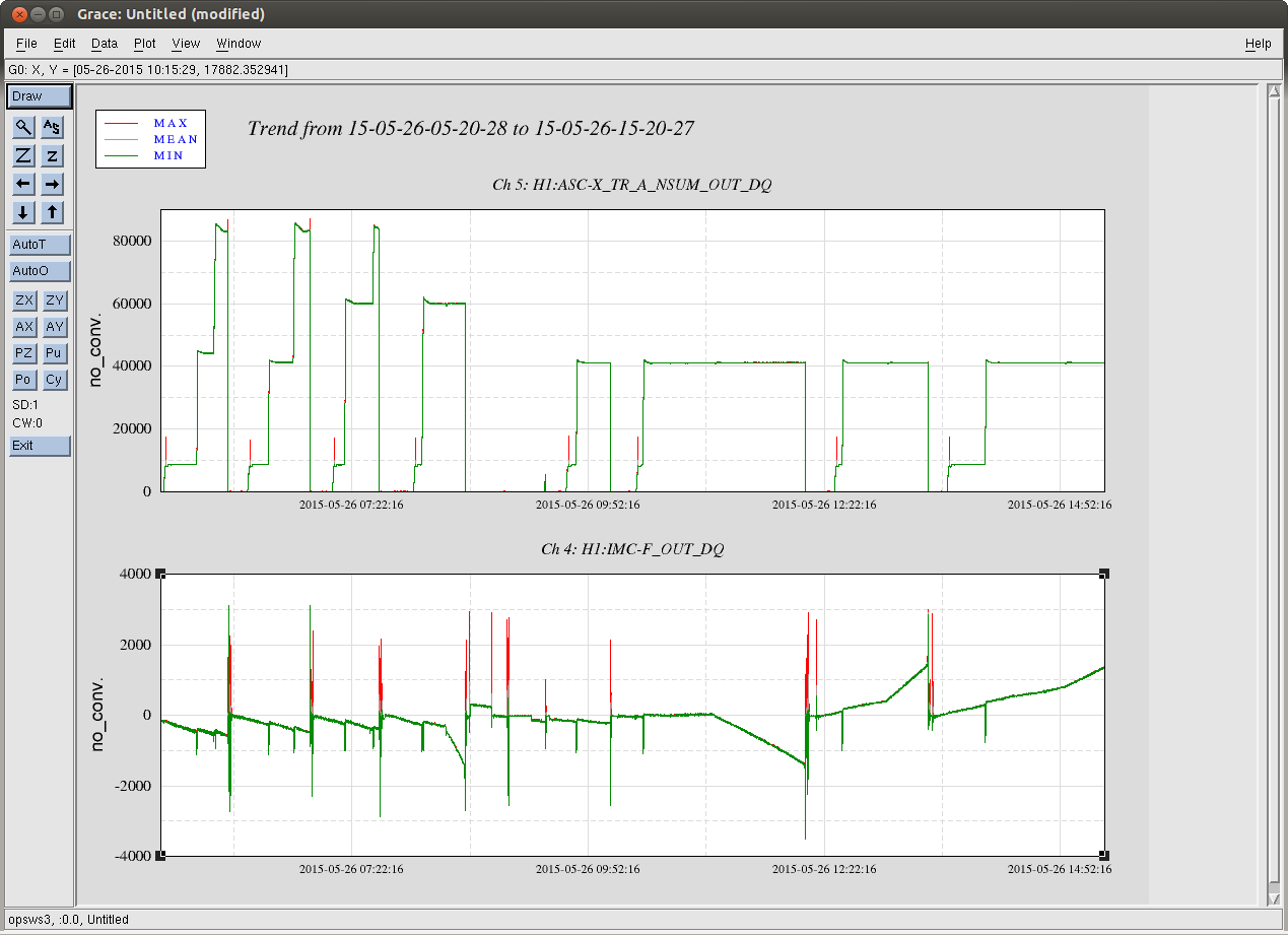
The slope of IMC-F is larger in the 15 Watt lockloss than the 10 Watts ones. A trend of IMC F and arm transmission from last night shows there are some inflection points in the slope of IMC F, although these don't corespond to changes in input power or changes in the state of the tidal state machine.
The other 4 locklosses that I looked at were not due to the IMC VCO, and I didn't come up with any good explanation for them. One notable feature in all of the others is the half a hertx oscillation in the ITM oplev damping loops, that starts when the power increased to 21 Watts, but it doesn't seem like this was the cause of the lockloss.
Tonight we were able to damp the roll modes with all of these settings, as well as ITMX for which we used -100 dB, bp13.9 (FM3+FM4) and a gain of 20. We also increased the gain for ETMX to 1000