= Morning Meeting =
SEI: BRS rung up
SUS: Sorry I couldn't hear
Richard: Shutter control needs work
Facility: Sorry, I couldn't hear again
3IFO: Moving things next Tuesday. Will be noisy.
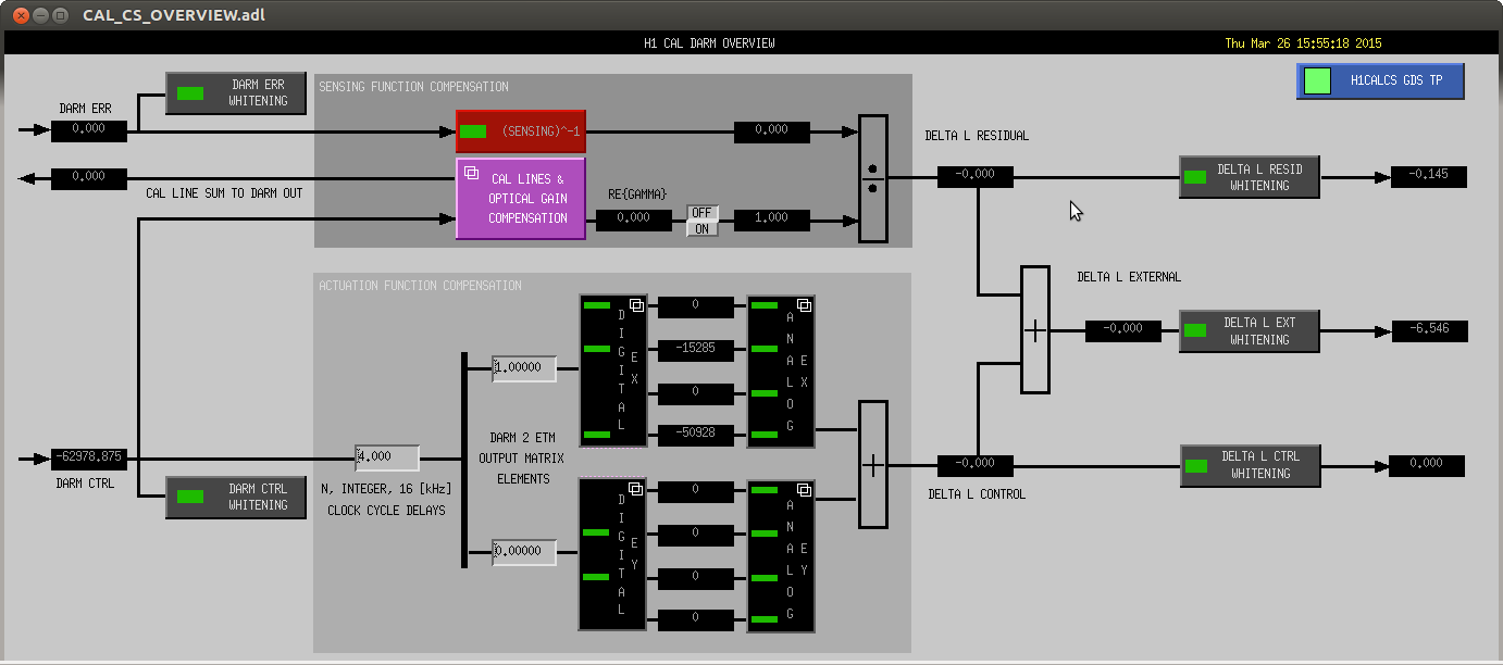
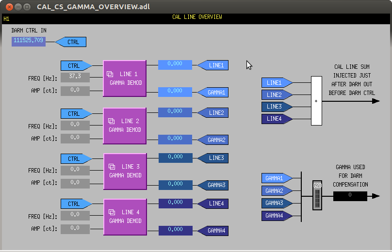
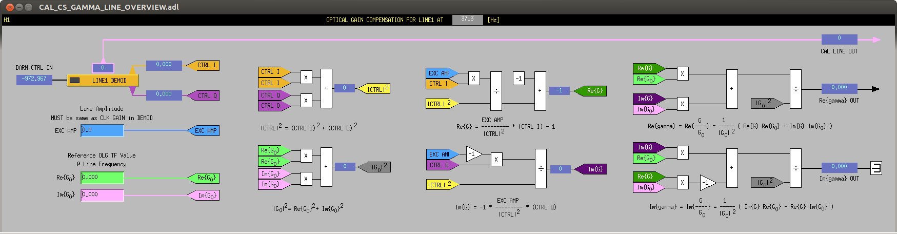
Jeff: Rebotting calibration front end model
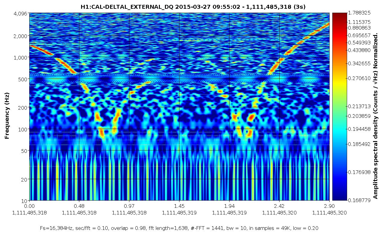
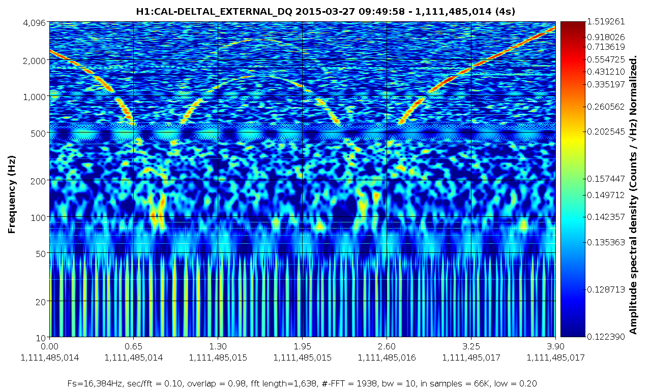
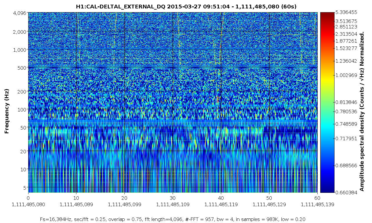
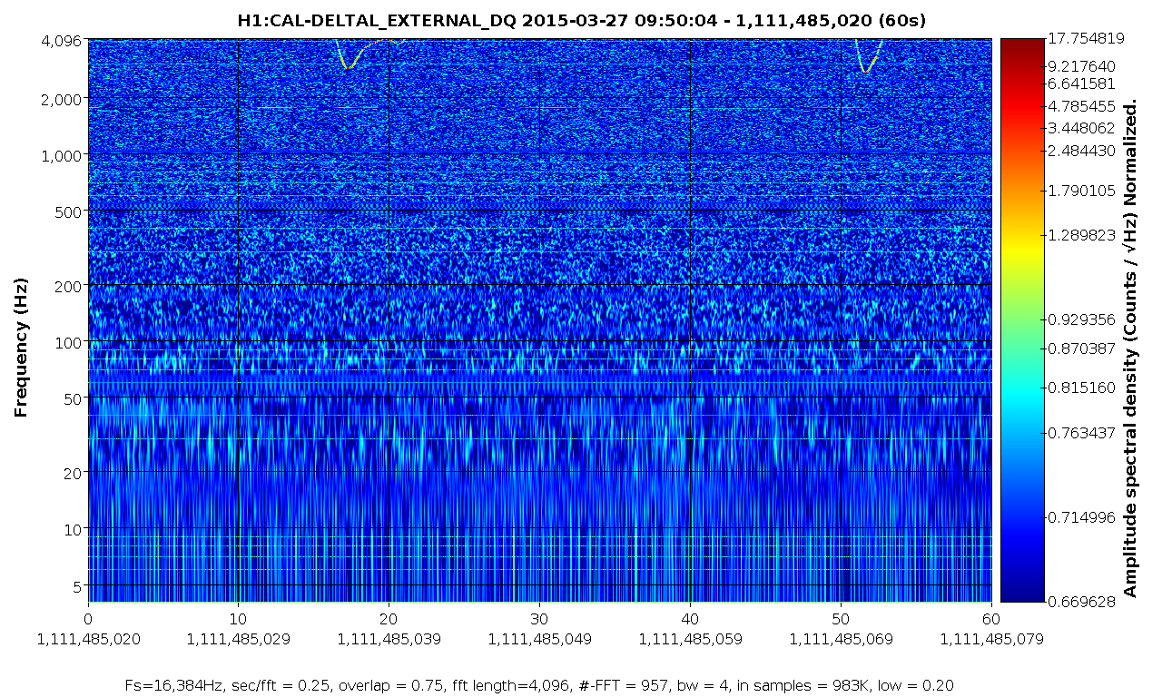
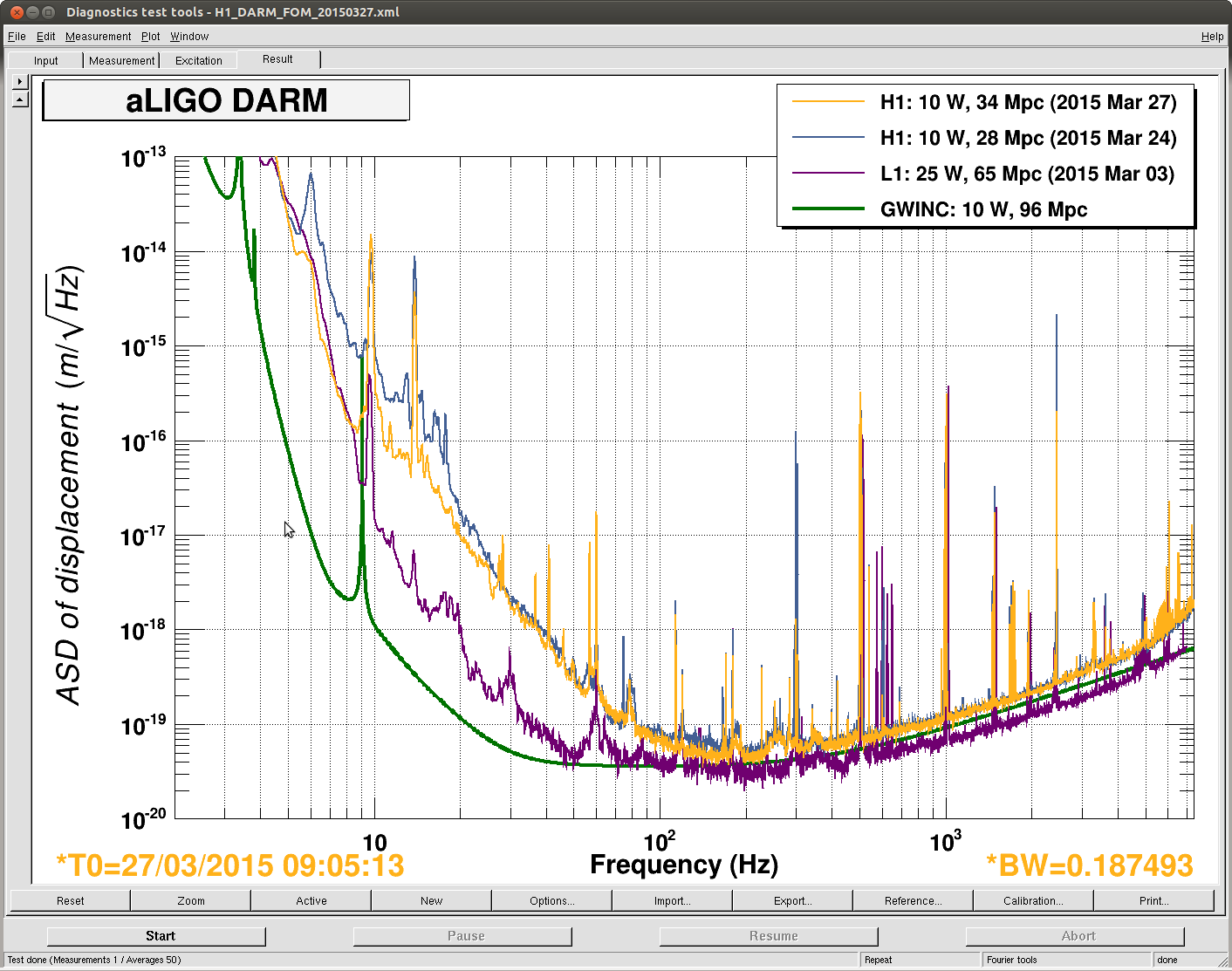
Sudarshan: PCal calibration
Lots of work permits...
= Activities =
Some times early in the morning: Karen and Cris to LVEA
7:00 Richard to EY
7:37 Richard back
8:19 Karen opening exit doors (LVEA)
8:41 Jim B to EY. Installing TCT
8:45 Fil to EY replace shutter box
Sudarshan and Rick to EX - PCal work
Jim to EX (stopped BRS damp)
8:52 Matt and Jason to H1 PSL ante room
5:56 Kyle to EY
9:00 both Jim came back
9:06 Jeff done with model changing
9:12 Matt and Jason back
9:19 Betsy and Travisto West Bay (3IFO stuff)
9:34 Kyle out of EY, to EX
9:39 Fil back
10:02 Kyle back
10:05 Andreas drop a bag at LVEA
10:18 Andreas back
10:30 Richard to LVEA 2k area (3IFO)
Jodi to LVEA
11:29 Jodi let Gary in, supervised.
12:00 Daniel and Sheila to EY
12:40 Corey to squeezer bay
13:46 Jodi back
13:51 Dan and Eli to EY
13:54 Rick and Sudarshan leaving EX
14:40 Dan and Eli back
Corey back
Happy 3IFO day