Evan, Sheila
We have been able to lock the IFO at 10 Watts with a recycling gain of 37. We also think that we can probably improve our inital alingment scheme by adding a servo from POP A to PR3 durring the INput align step. We've closed loops around ITMX from the TRX QPDs, these were stable for almost an hour before we dropped the lock for other reasons, and helped keep the X arm build up stable as we increased the power.
Variation on Inital Alingment
At the beginning of the evening, our alignment resulted in a rather low recycling gain (15 or something) which resulted in difficulty locking. This was probably because the ITM camera references would have moved 18033. We have now gone through an initial alignment with some extra steps which brought us back to a decent recycling gain (35 before any manual adjustment or full lock ASC).
-
First we locked the X arm with both green and IR, and ran two green WFS loops (ETM and TMS), green ITMX camera loop, and the input align WFS loops (REFL WFS to IM4+PR2). In this configuration Evan moved PR3 to bring the spot position on POP A close to zero, which is the position it was in during a high recycling gain lock last night. (0.05 Yaw, -0.08 PIT). This move also increased the COMM beatnote strength, to above 4 dBm. After this we set the green ITM camera reference again.
-
Then we used this input beam and with the Y arm optics misaligned steered the BS to get red light on the ETMY baffle PDs. This was a rather different location than what we found in october 14321. We did this by hand since we have never set the gains and phases correctly to use the ditherAlign script for the BS.
|
|
PIT (urad) |
Yaw |
|
PD1 |
169.2 |
-311.4 |
|
PD4 |
134.5 |
-278.9 |
|
mean |
151.85 |
-295.15 |
-
After this we locked the Y arm on green and IR, with green WFS running on the ETM and TMS. We moved the ITM to maximize the red build up in the arm, and let green WFS take care of the ETM. After this, we reset the ITMY green camera reference. Ideally, we would have used red WFS to
-
After that we checked MICH dark which was misaligned by about 0.6 urad, we adjusted the BS to get a nice dark port.
-
Then we did the rest of our initial alignment scheme as usual, PRM ALIGN and SRC align.
This resulted in a recycling gain of about 35, so it seems like this was a sucsesful approach at least once. If there is time for some day time commissioning tomorrow, it would probably be helpful to add to the INPUT align state a loop which actuates on PR3 to center the beam on POP A. Commissioning the dither Align script for the BS to ETMY baffle PDs might also be helpful, but this is a lower priority because we aren't sure that step is necessary.
Since we have seen this week that many things (CARM offset reduction, violin and roll mode damping, and ASC error signals, possible radiation pressure instability on the ITMs) change when we go from a bad recycling gain to a good one, it seems like we will want to improve our initial alignment scheme enough to consistently bring us to a high enough recycling gain that we can use consistent settings for lock acquisition.
Avoiding oscillations durring power up
We ran into the oscillation in ITM pitch which we think is due to mis centering and radiation pressure on the ITMs several times tonight. It seems like we are more stable when the recycling gain is high, we have also slowed down the final CARM offset reduction and the power increase.
Closing ITM loops
We were able to close loops around ITMX from the QPD error signals we found last night. Here are settings:
DSOFT P (ITMX P) error signal 1.71 TRX A -1 TRX B FM offset 0.08, FM2,3,4 gain -700,000, top mass offloading on
DSOFT Y (ITMX Y) error signal 1.84 TRX A -1 TRX B FM offset -0.1, FM2,3,4,6 gain 600,000, top mass offloading on
both of these loops respond in a 2-3 seconds.
DARM OLG
Evan made a measurement of the DARM OLG, this was when we still on ETMX, DC readout with low frequency boost, and a recycling gain of 35. 11 Watts input power.
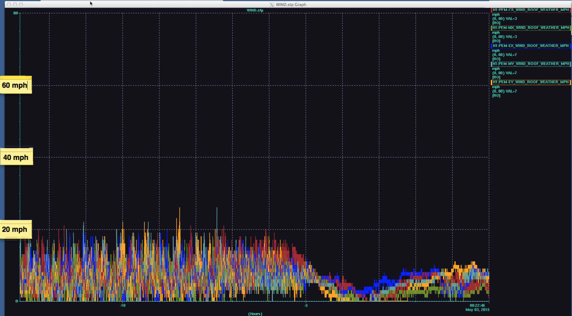
Now a large earthquake has tripped most of the seismic platforms.


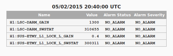

I've taken care of the changes noted by the SDF and accepted the new settings.
FSS resonance threshold had also changed from .6V to .55V. This was also noted and accepted in the SDF.