J. Kissel

Having processed the last two DARM open loop gains -- the first measurements out to 5 [kHz], and the first measurements after we've tuned up the ASC loops to give us a consistent recycling gain of 35-40 -- I can now make the following statements:
- The DARM Coupled Cavity Pole (CCP) frequency is now consistently much closer to the "as designed" value. The measurements are consistent with a model of the DARM loop using a CCP of 355 [Hz].
- The ETMY ESD's driver pole frequency is 2.2 [kHz], not the colloquially thrown about 2 [kHz].
- I've added the violin modes to the model of the QUAD suspension, and they have no appreciable effect, but I'll leave them in for completeness.

On what these measurements and changes to the model mean for the uncertainty (precision and accuracy):
- The modeled unknown time delay remains at 0 +/- 5 [us].
- The frequency dependent uncertainty in the calibration model remains at +/- 2.5% in magnitude and 1 [deg], but I've data to back up that this extends out to the entire required* frequency band 10 and 2000 [Hz]. See attachment 2015-05-02_FittedCCP_H1DARMOLGTF.pdf (* OK, what *used* to be the requirement. The requirements are now extended albiet inflated out to 5 [kHz]; see T1300950)
- Over these last two measurements, the scale factor used to match the model against measurement has only varied by 3%. Indeed, if you cluster the eight measurements, grouping by CCP, then the standard deviations of the three, three, and two measurements are 7%, 41%, and 3%. However, the total standard deviation of all measurements is 22%, and the latter two measurements are only 1 day apart. From the data I have, I'm still not confident in decreasing the scale-factor uncertainty below 22%; perhaps PCAL can make a better statement on this (but I fear the current Mini-Run noise is too high for the low-frequency PCAL line). See
2015-05-02_upto5kHzOnly_FittedCCP_H1DARMOLGTF.pdf
- The current calibration installed in the CAL-CS model is incorrect, both in frequency dependence and scale factor.
    - Frequency dependence: The CAL-CS filters assume a DARM CCP of 389 [Hz] in the sensing path, and an ESD Driver Pole (ESDP) of 2.2 [kHz] in the actuation path. For the latest lock stretches, that inflates the uncertainty of CAL-DELTAL_EXTERNAL_DQ with a known, systematic error of
      current / correct = ( 1 / (current CCP / correct CCP) + (current ESDP / correct ESDP) ) / (properly normalized)
                        = ( 1/zpk(-2*pi*389,-2*pi*355,355/389) + zpk(-2*pi*2e3,-2*pi*2.2e3,2.2e3/2e3) ) / 2
      which translates to as much as a 7% magnitude error at 1 [kHz], and 1.8 [deg] swing in phase surrounding 1 [kHz].
      This is demonstrated in 2015-05-02_H1CAL-CS_Systematic.pdf,
      This is also reflected in the statistical uncertainty estimate. All comparisons are shown if a 389 Hz CCP and 2 kHz ESDP were used in 2015-05-02_389HzCCP_2p0kHzESDPole_H1DARMOLGTF.pdf.
    - Scale Factor: this depends on whether we want to use 22% or 3% for our scale factor uncertainty. If 22%, then the last two lock stretches still fall within the 1.1e6 +/ 22% [ct/m]. But, if the scale factor is 1.2725e6 (the mean of the last two scale factors), then that indeed falls outside of 1.1e6 +/-3%
    - We *still* have not implemented any compensation for the analog or digital, AA or AI filters.
- The GDS/DMT produced calibration is off just as much as the CAL-CS produced calibration, because GDS/DMT calibration is using the same filters.

------------------
All parameter files have been committed (with updated ESD driver poles, and fitted DARM coupled cavity poles) here:
/ligo/svncommon/CalSVN/aligocalibration/trunk/Runs/PreER7/H1/Scripts/
H1DARMparams_1109994128.m
H1DARMparams_1111998876.m
H1DARMparams_1112399129.m
H1DARMparams_1112933759.m
H1DARMparams_1112942996.m
H1DARMparams_1113119652.m
H1DARMparams_1114541595.m
H1DARMparams_1114634170.m

Which are processed by the DARM model function here:
/ligo/svncommon/CalSVN/aligocalibration/trunk/Runs/PreER7/H1/Scripts/H1DARMmodel_preER7.m

And then compared with the script here:
/ligo/svncommon/CalSVN/aligocalibration/trunk/Runs/PreER7/H1/Scripts/CompareDARMOLGTFs.m


Okay maybe not too soon. PSL just tripped....
20:40 PSL untripped but having trouble locking IMC. I cleared all the IMC WFS history but that didn't help. Still working on it.
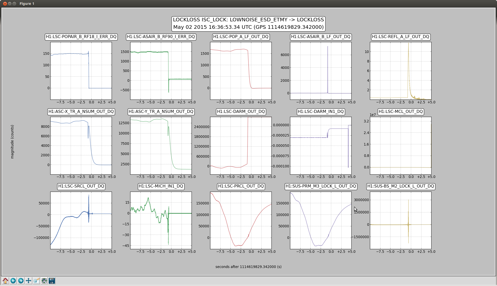
22:18 Locking again on LOWNOISE_ESD_ETMY at ~11 Mpc. I had to tweak all the IMC optics to get IMC to lock again after PSL tripped. Intent bit switched to Undisturbed at 22:28.
23:01 Lock loss. PSL tripped AGAIN.