Sheila, Koji, Robert, Evan, Alexa, Dan
We have made several measurements of backscattering from the OMC. It seems like the reflectivity of the OMC is smaller by a factor of about 20 than what was seen at LLO, and it seems that backscatter from the OMC is probably not limiting our DARM spectrum.
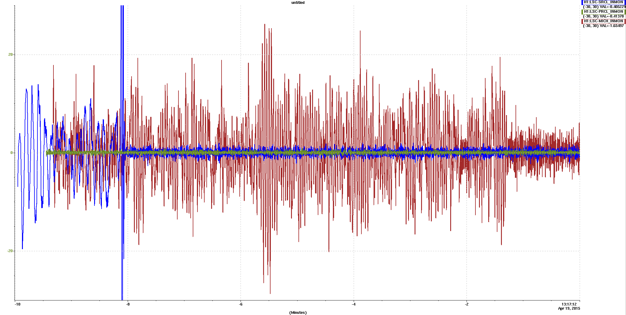
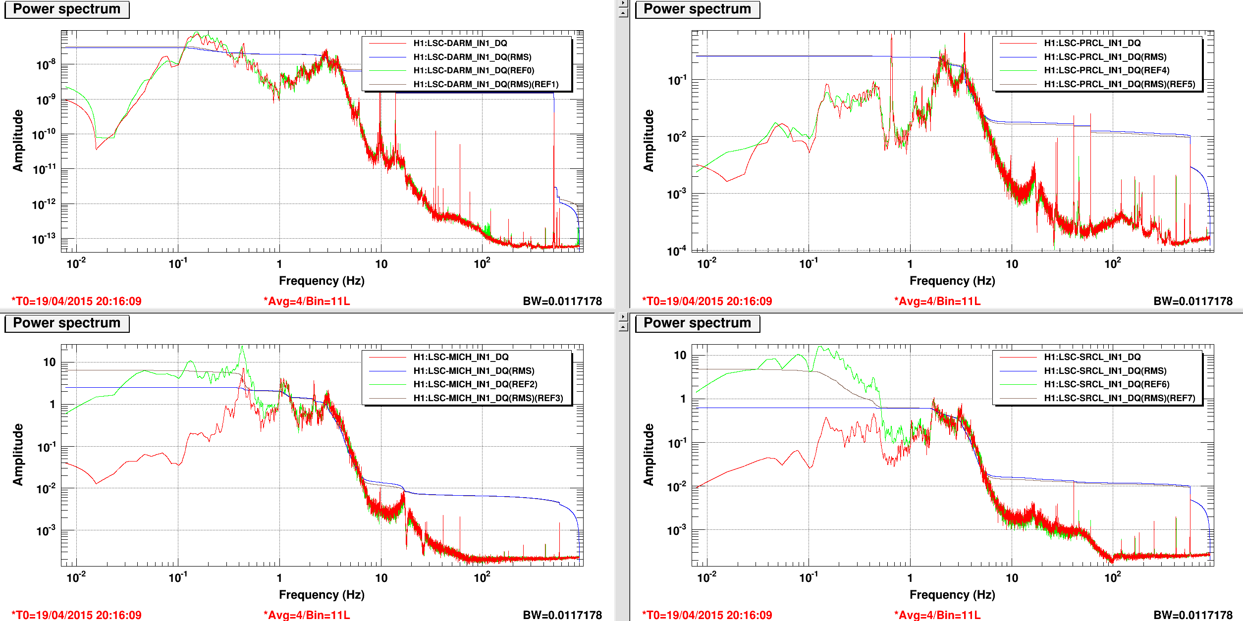
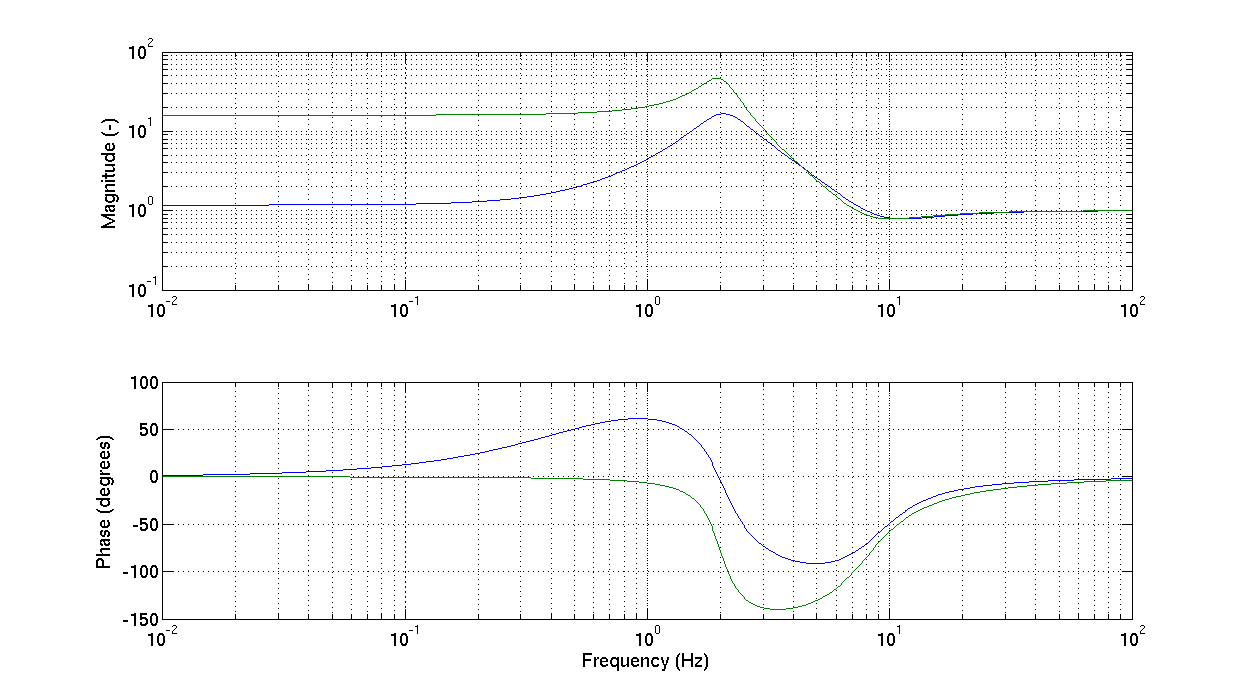
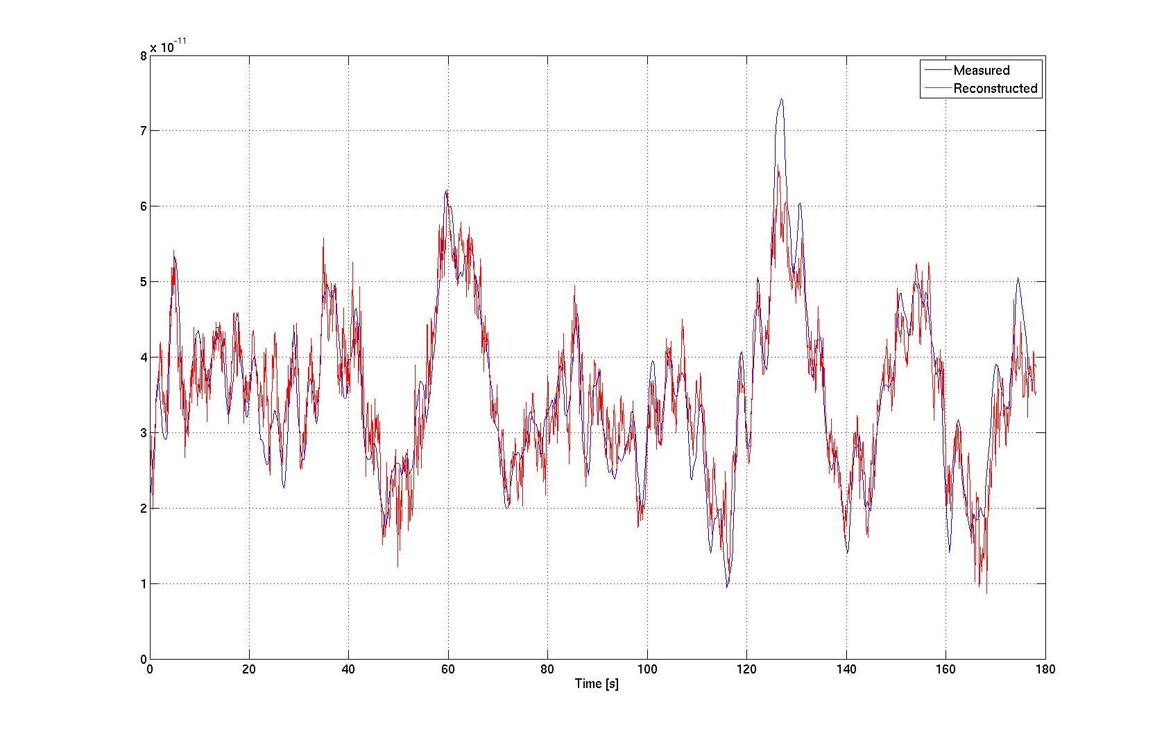
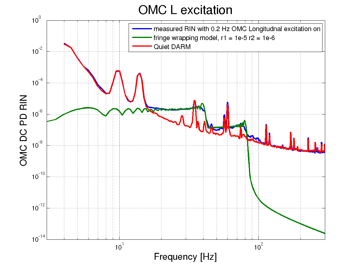
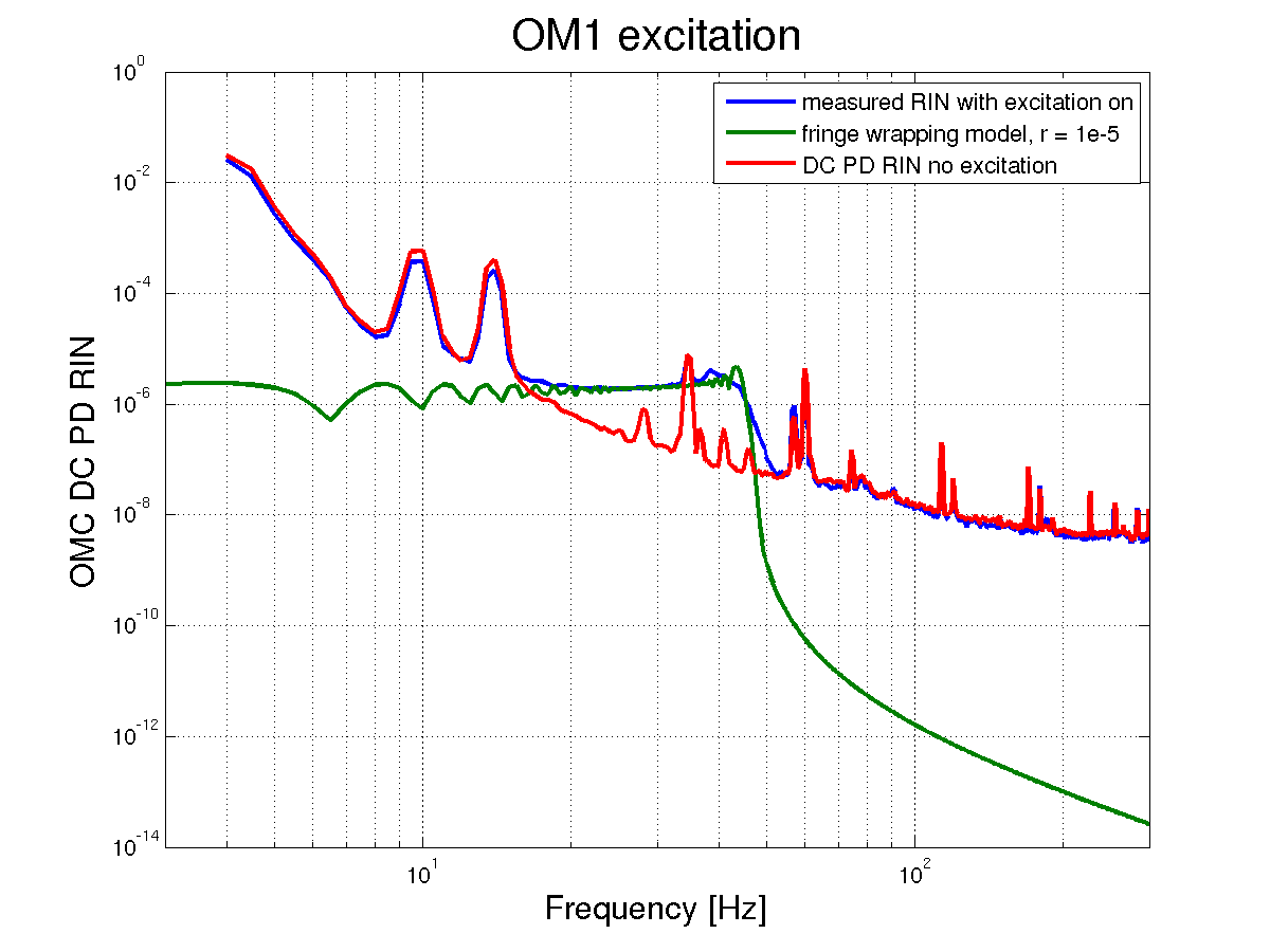
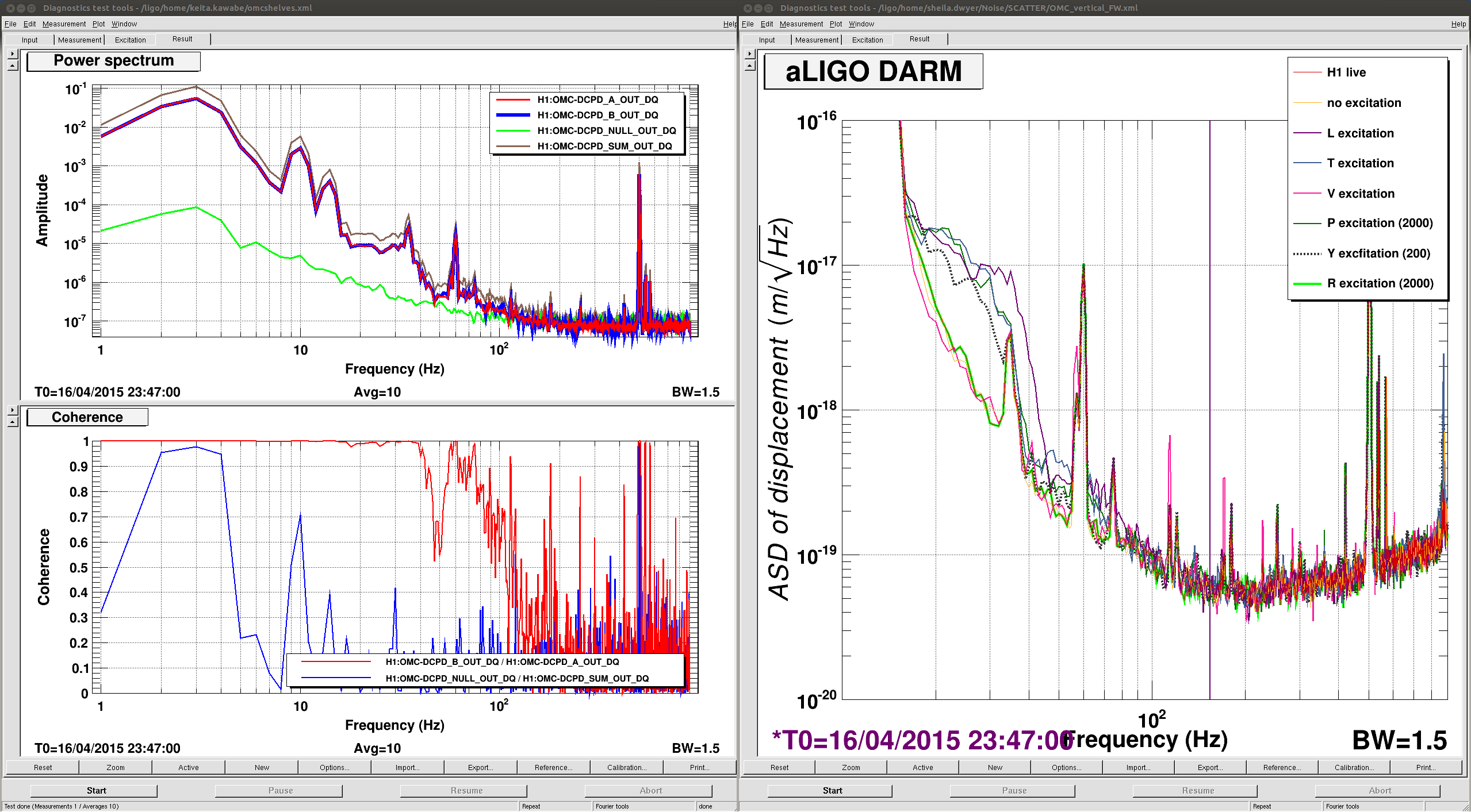
Two nights ago, we measured fringe wrapping by exciting the OMC suspension in the longitudnal direction, as well as by exciting OM1. (related alogs 17910 17904 17882) The attached plots show the DCPD RIM, with the DARM loop supression removed, with the excitations on.
-
First, we noticed that the osem calibration must be wrong, for both OM1 and the OMC. For the OMC our knee frequency around 45 Hz indicates that indicates that our excitation amplitude was about 35.25 um. The osem readback indicates that our exitation amplitude was 11.8um, if we assume that this path length is double passed the osem is underestimating the motion by about 50%. The story for OM1 is similar, the osem indicates that OM1 was moving with an amplitude of 6.25 um, but the path length modulation must have been about 20 um based on the knee frequency. (Tobin's thesis, p 45)
-
When we excite the OMC, we see two scattring shelves, the second has a finge velocity twice that of the first path. For the first shelf we get an amplitude reflectivity of 1e-5, for the second shelf it is 1e-6. These are eyeball fits, but they seem to be good to within about 15%. At LLO (alog 13607) similar measurements showed an r = 2e-4 for their first shelf.
-
One speculation is that the first shelf could come from scattering within the OMC itself, and the second from the OMC refl path. Yesterday (after these measurements were made) Koji realinged the OMC refl QODs, and the amplitude of the second shelf is reduced today.
-
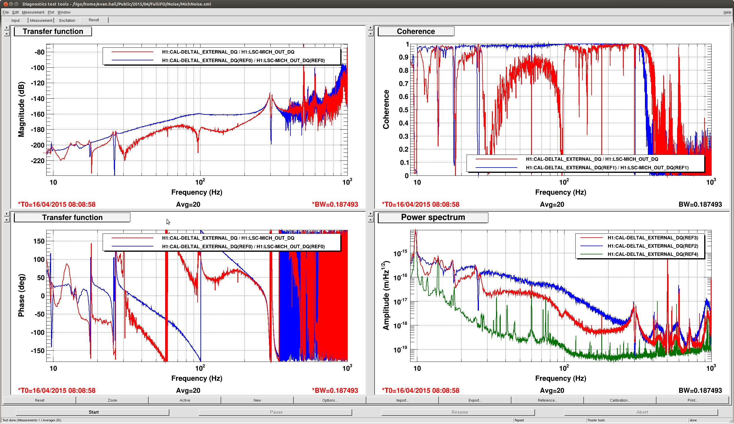
FOR OM1 we only see one shelf, because OM1 is not the scattering source. With this we are only modulating the path length between the IFO and the scattering source. However, we measure the same reflectivity as the first shelf when exciting the OMC, so the two measurements are consisitent.
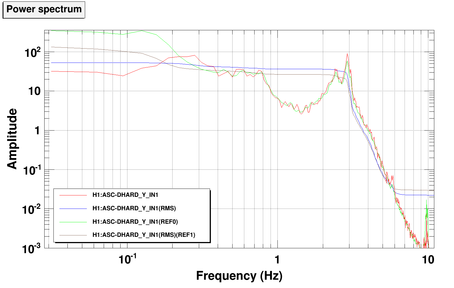
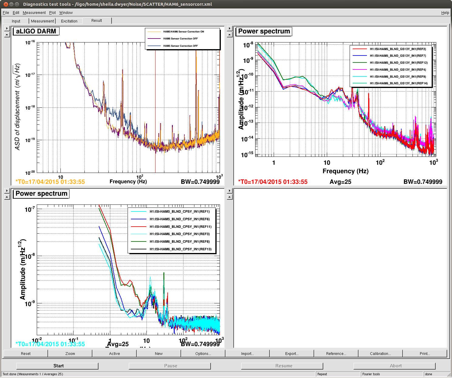
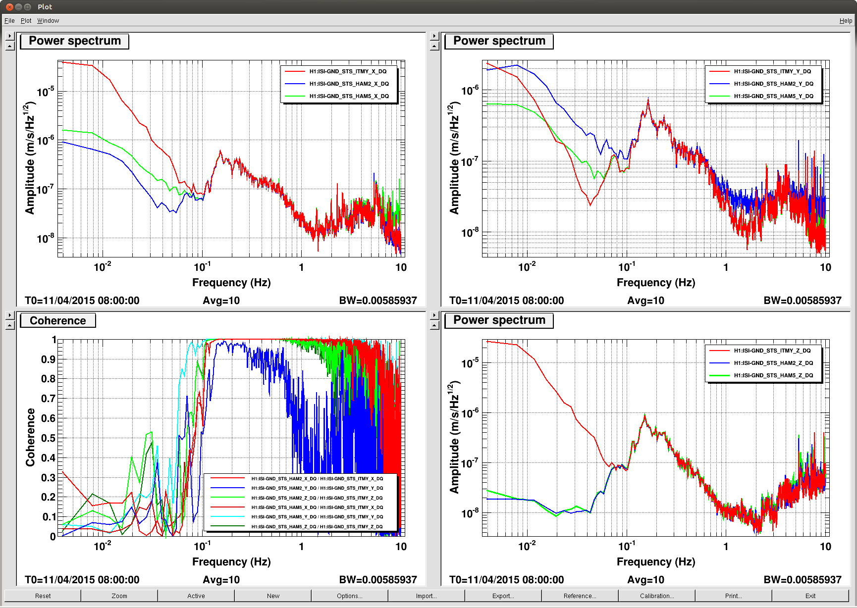
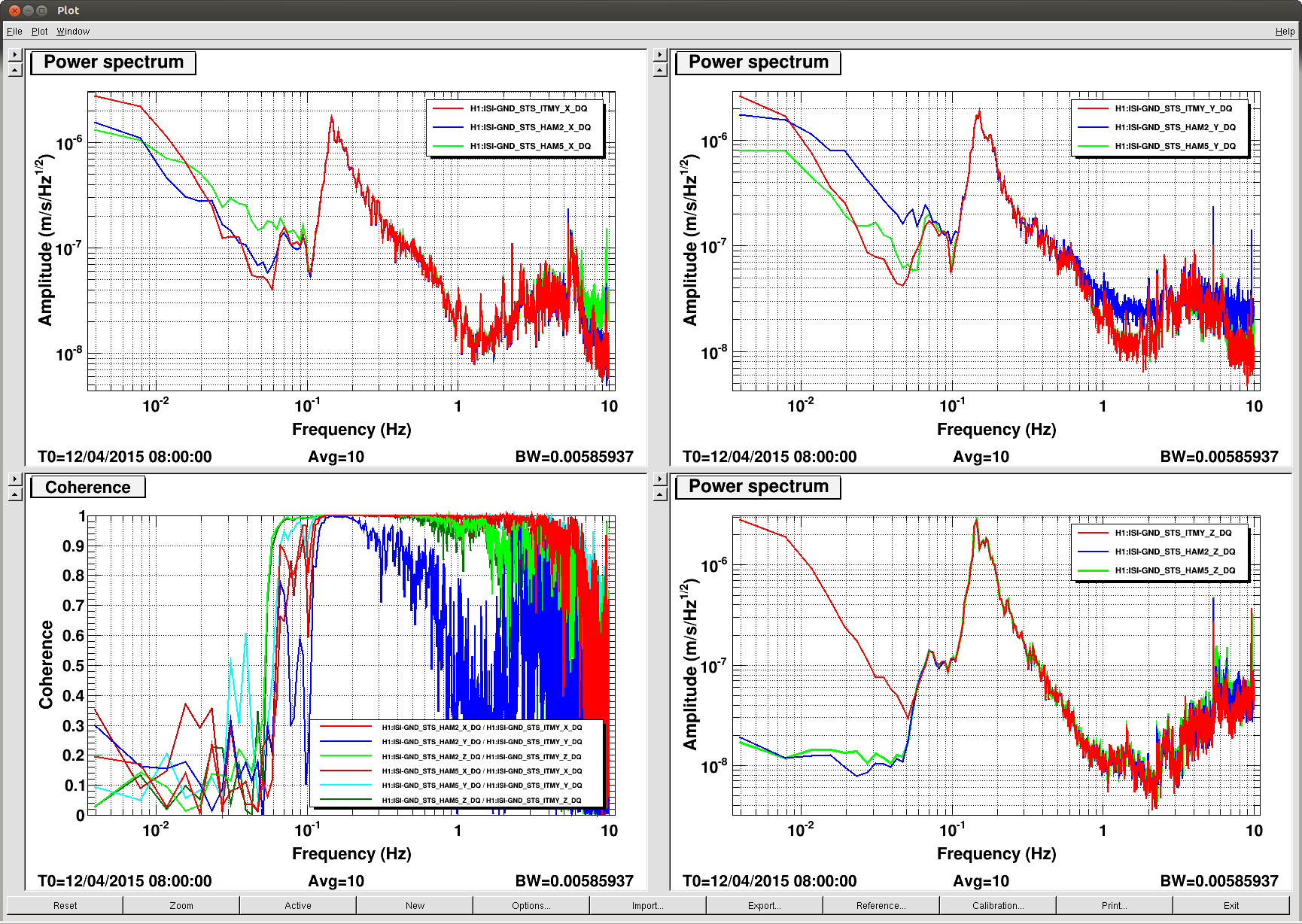
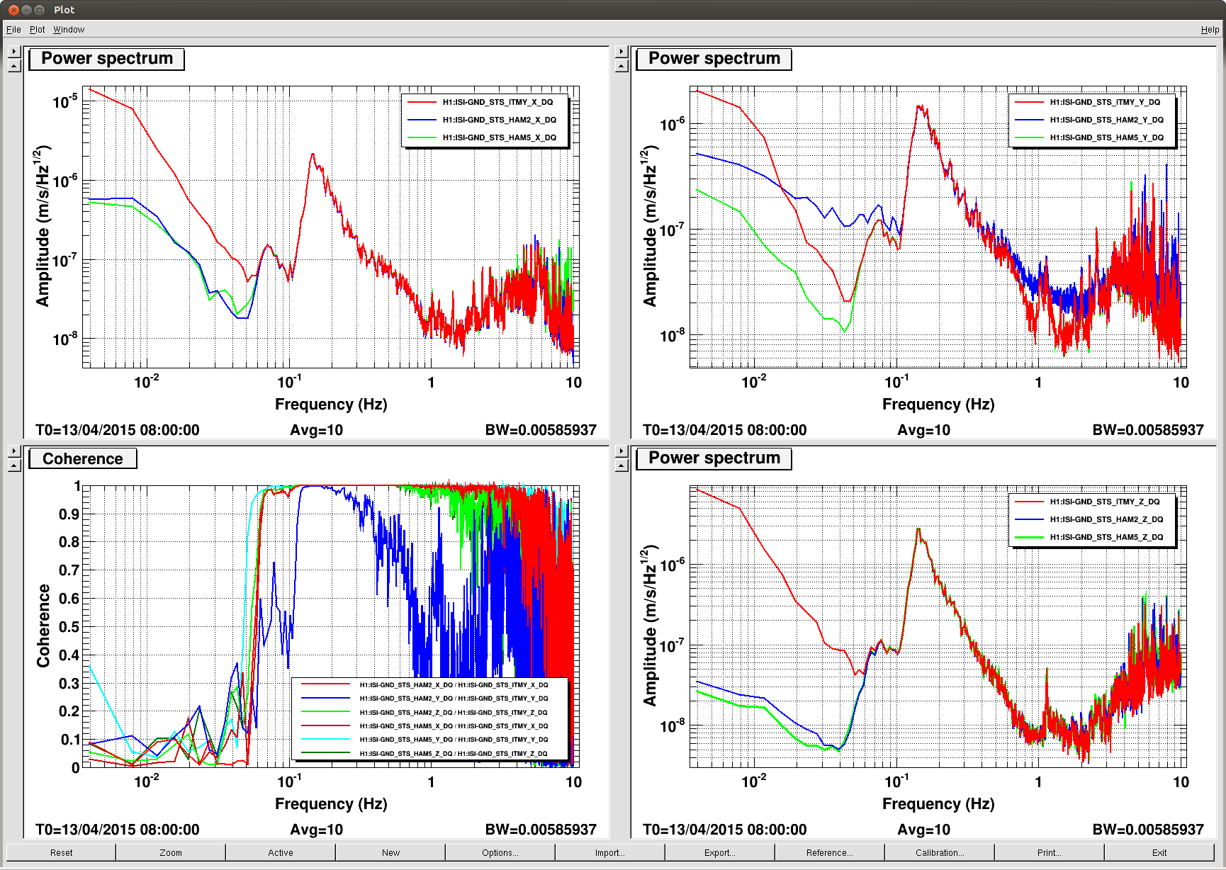
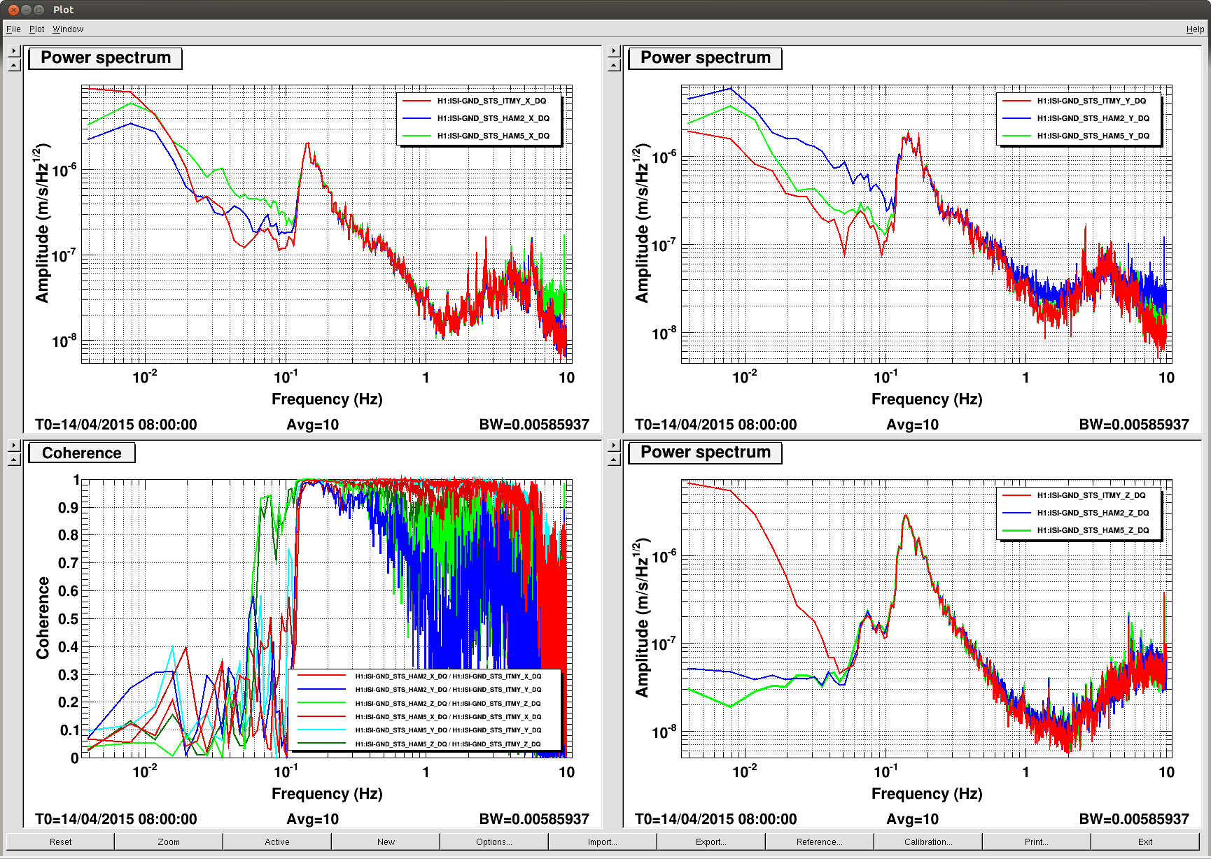
Tonight Jeff made a test of turning off the HAM6 sensor correction, as was done at LLO (third attachment) (LLO alogs 16814). The spectrum is attached, but we do not see the dramatic fringe wrapping seen at LLO. We would expect the impact to be smaller here than in LLO because our scattering amplitude is smaller and it is also likely that the microseism could have been smaller here.
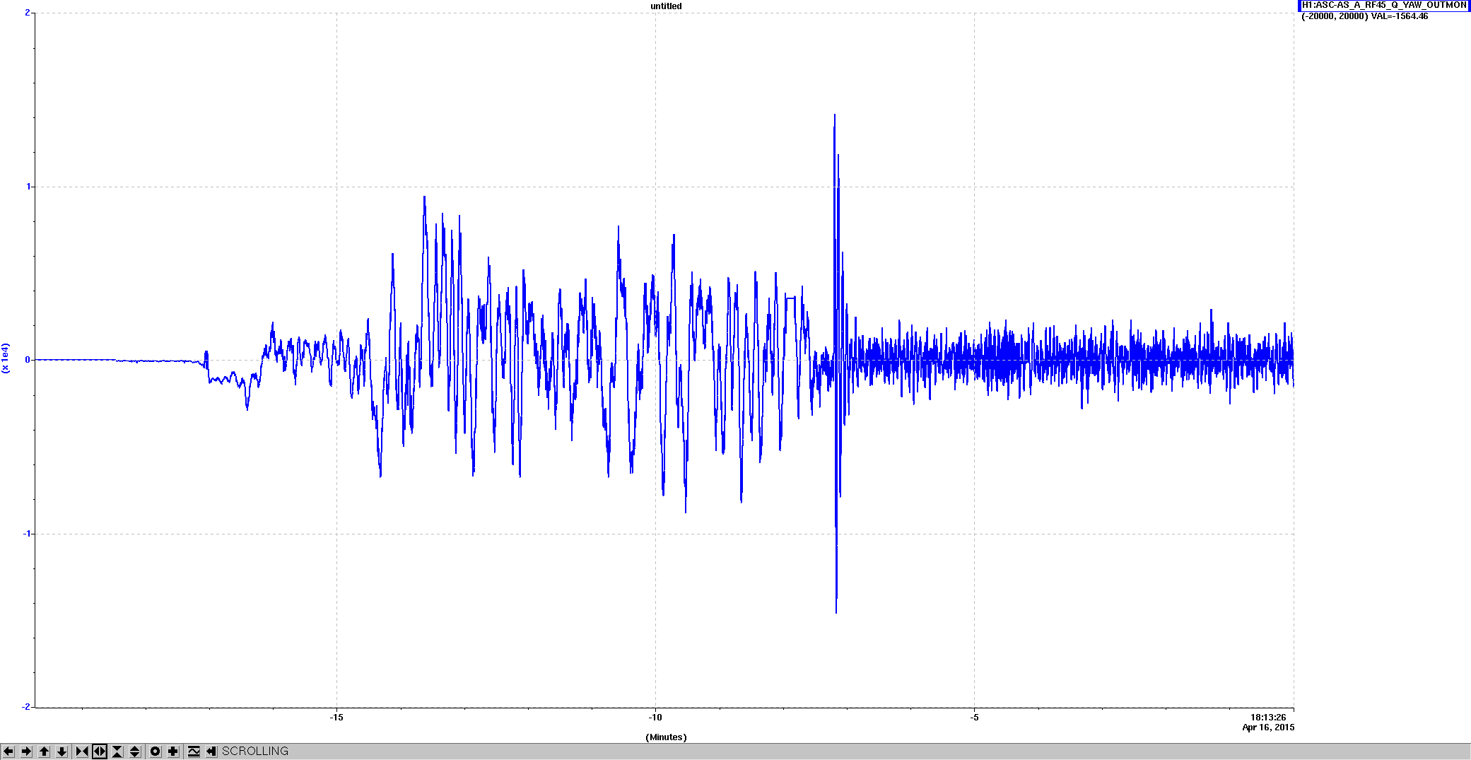
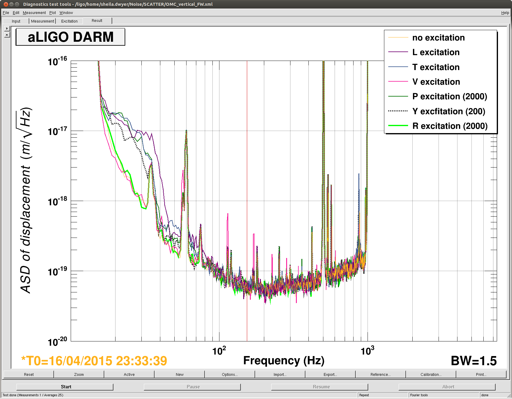
Today we Robert Koji and I made injections into all 6 DOFs on the OMC to see fringe wrapping. We saw nothing by exciting roll or vertical, we were able to produce shelves by exciting L, T, P and Y. The last screenshot attached shows the sectra with the various excitations on. For the record, here are times, all excitations were at 0.2 Hz, into the test filter banks. While I've attached spectra of these, several off these shelves were moving around durring the measurement because of some lower frequency motion.
|
DOF |
ampltide counts |
time April 16-17th UTC |
|
L |
20000 |
23:47-23:51 |
|
T |
20000 |
23:59-0:05 |
|
V |
20000 |
0:14-0:18 |
|
P |
2000 |
0:24-0:29 |
|
Y |
200 |
0:31-0:35 |
|
R |
2000 |
0:39-0:42 |