Alexa, Elli, Sheila, Kiwamu, Rana, Evan
Summary
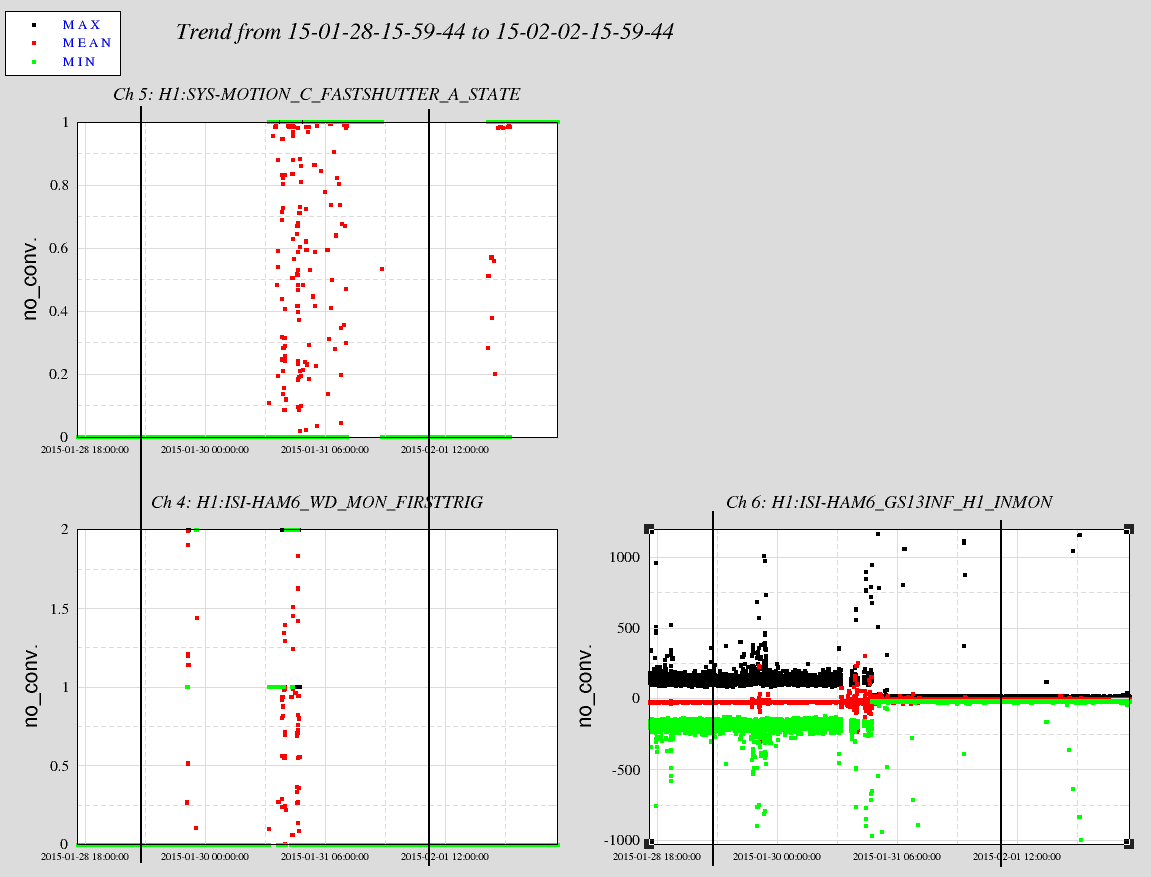
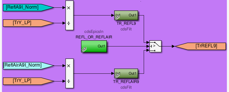
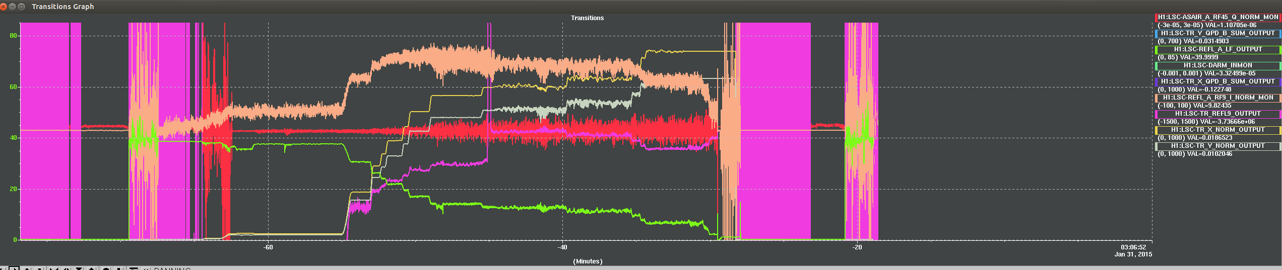
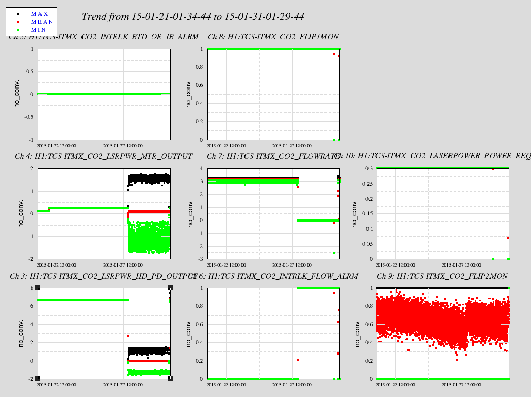
With CARM controlled by a combination of sqrt(TRX+TRY) and TR_REFL9 (i.e., REFL9I normalized by TRY), we've achieved a power buildup in each arm that is 800× the single-arm buildup. We believe this corresponds to a CARM detuning of 5 pm.
At this point, REFL_A_LF is at about 2.3 mW, compared to 40 mW when the arms are anti-resonant. If this is truly an indication of the power reflected back from the PRM, this means that the visibility of the interferometer is in excess of 90 %. We do not have TCS on today.
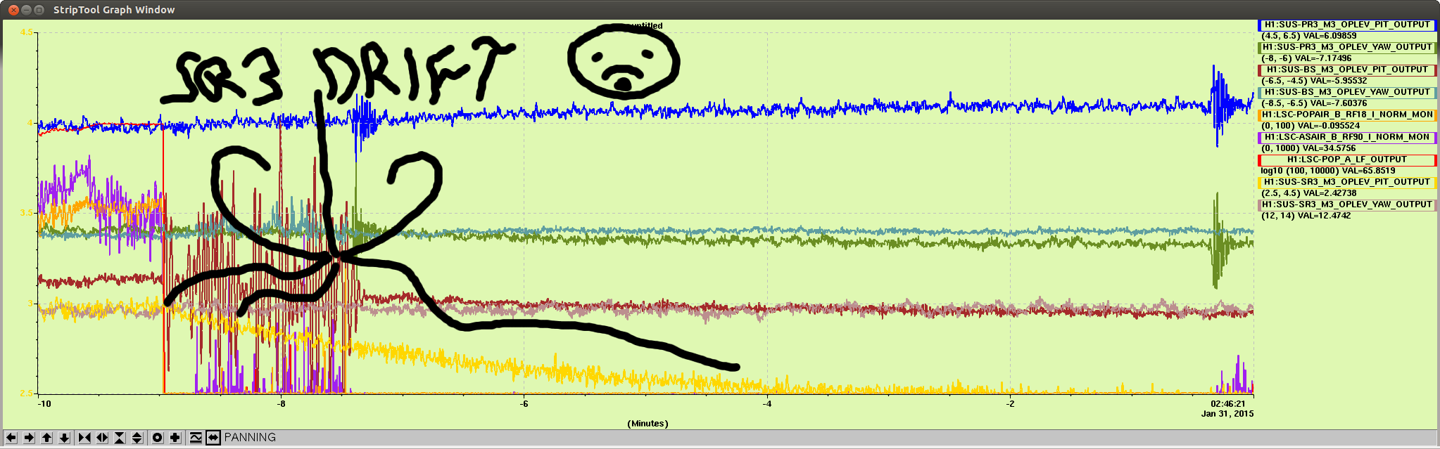
One major roadblock to further progress seems to be angular instability that is seen at the AS port. We have ASC feedback from AS_B_45_Q to ETMX and ETMY, but the bandwidth is too low to suppress the 1 Hz motions that we see. We may need to spend some time increasing the WFS bandwidth, or resort to more aggressive oplev damping.
Details
A laundry list of things we've done today to troubleshoot the transition:
-
Locking at 4 W input power. This appears to reduce the amount of angular instability during CARM offset reduction.
-
Engaged oplev damping on ITMs.
-
Increased the DHARD WFS BW. The gains are now 0.1, FM2 (+20dB) is no longer on compared to Elli's old alog (LHO#16345)
-
Changed the DARM loop shape (LHO#16387) to achieve higher bandwidth.
-
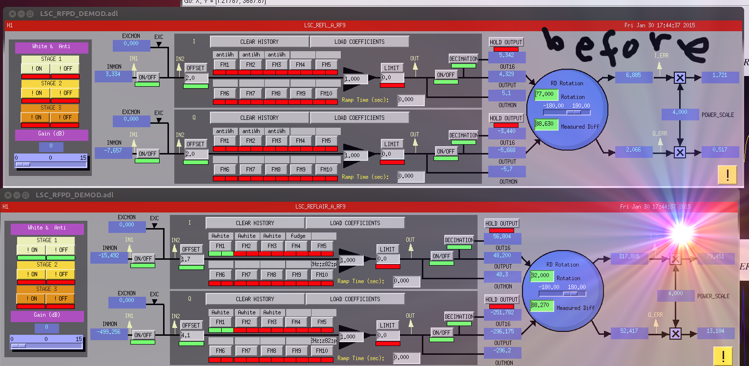
Switched from REFL_A to REFLAIR_A to avoid saturation while locking (LHO#16381).
-
Because TCS was accidentally turned off (LHO#16385), we decided to retune the demod phases of the 3f signals. With CARM controlled by sqrt(TRX+TRY), we've adjusted the phases as follows:
-
27 MHz: 91.3°→111.8°
-
135 MHz: 65°→25°
-
We took a TF from TR_REFL9 to sqrt(TR) at -25 ct of offset on sqrt(TR). Above 10 Hz, the TF was about 50 dB with -180° of phase. Below 10 Hz, the TF began to rise. Therefore, we installed a 1.6 Hz pole, 40 Hz zero in the TR_REFL9, and +50 dB. This behavior does not seem to correspond with simulated TFs given, e.g., in T1400298.
Based on the measured losses in the arms (an average of 110 ppm), we expect an interferometer recycling gain of 32 W/W and a coupled cavity pole of 0.6 Hz (i.e., 9 pm) [using eqs. 6 and 8 from Fritschel et al. 2001]. Therefore, we believe that the arm buildup should be about 1000× the single-arm power with CARM at 0 pm. This is consistent with earlier estimates made by others (LHO#15390, T1000294).
A list of transition steps not yet implemented in the guardian:
-
Increase the gain of IN1 on the IMC board by 6 dB.
-
Starting at a sqrt(TR) offset of −20 ct, ramp the offset to −30 ct while reducing the DARM gain in the input matrix from 40 ct/ct to 20 ct/ct.
-
Turn off the WFS (they appear to flip sign around here).
-
Ramp the offset to −36 ct, and ramp the DARM input matrix coefficient to 8 ct/ct. Turn on the WFS with the opposite sign, and 10 dB less gain.
-
Turn on TR_REFL9I→CARM feedback with an input matrix gain of 3 ct/ct, and no TR_REFL9I offset.
-
Adjust the CARM offset to -41 cts, and hold the TR_X/Y_NORM outputs
Our last three attempts are 11:24:48 UTC, 11:00:27 and 10:37:35 Jan 31.