Jim, Hugh, Krishna, Fabrice:
we have been chasing problems in HAM3:
- one aspect of the problem is that the Z sensor correction doesn't perform well. A large peak at 0.6 Hz appears in the spectra, in all directions, when the sensor correction is ON.
- another aspect of the problem, related, is that there is low coherence from the ground seismometer to HAM 3 geophones. This is more a broadband effect.
- another puzzling effect is that the Z sensor correction makes X, Y performance better.
We have been investigating to find out whether this is a CPS sensor noise issue, a mechanical issue (rubbing, hitting, mechanical shortcut....), and/or a loop shaping issue.
Some comments and results of the investigation:
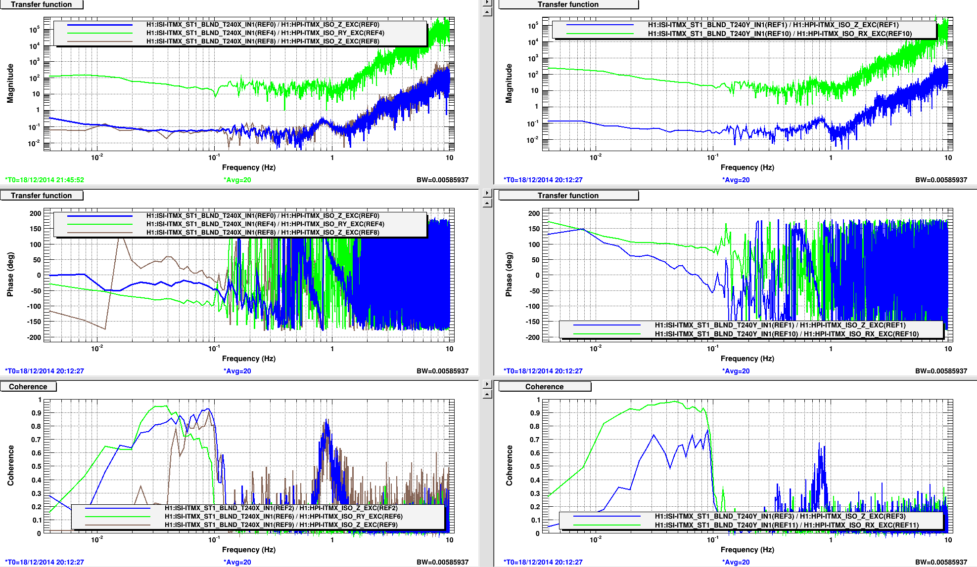
- page 1, the sensor correction is off, the ISI is damped, the coherence from ground to HAM3 is excellent.
- page 2, isolation loops and sensor correction are ON. The coherence drops at 0.6 Hz.
- page 3, the sensor correction is off. Coherence between ground to ISI is no good. But the coherence between ground and HEPI is good. So HEPI is likely not introducing the noise.
- page 5, I ran harmonic tests to see if something is hitting. We did not find anything obvious.
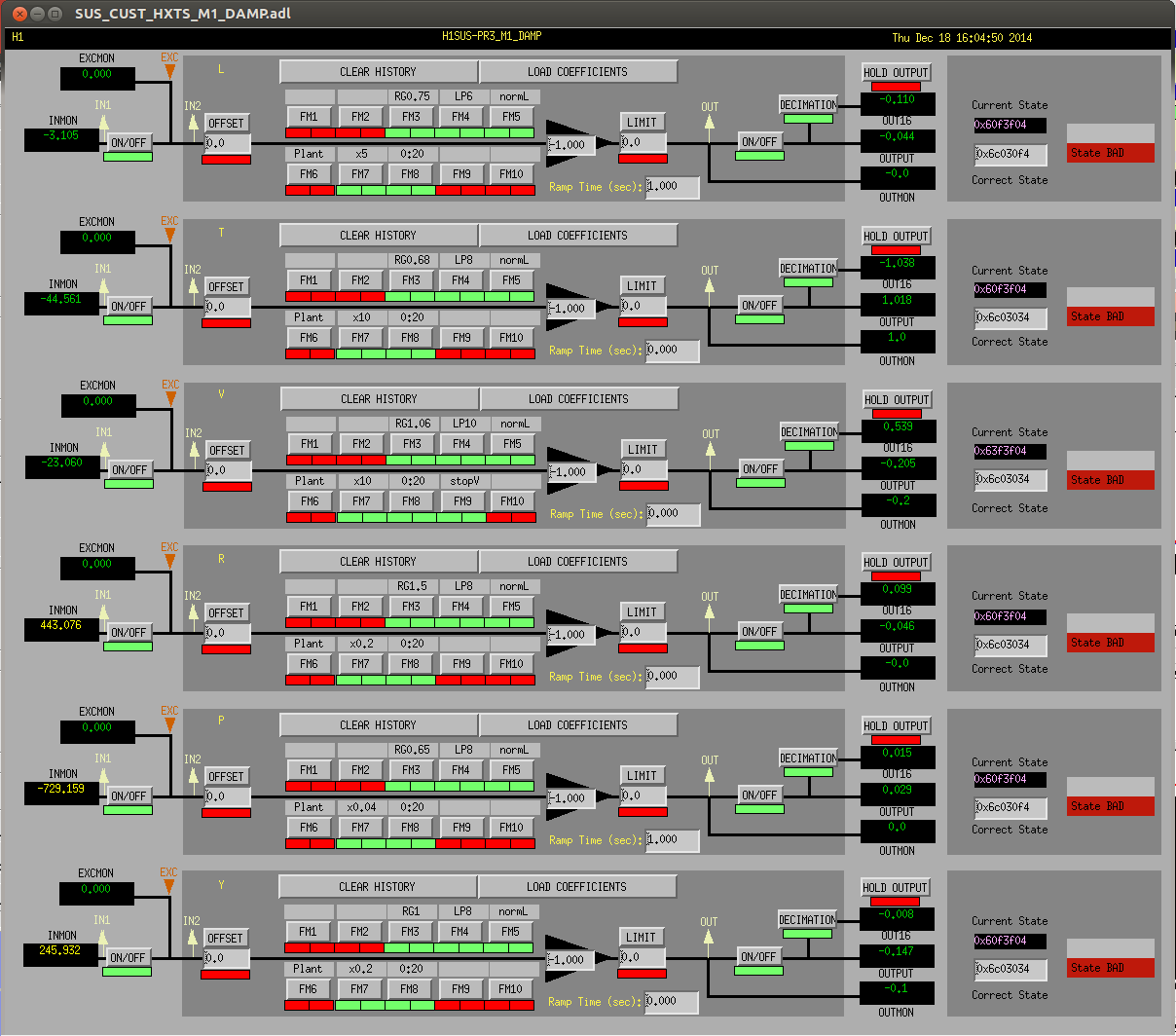
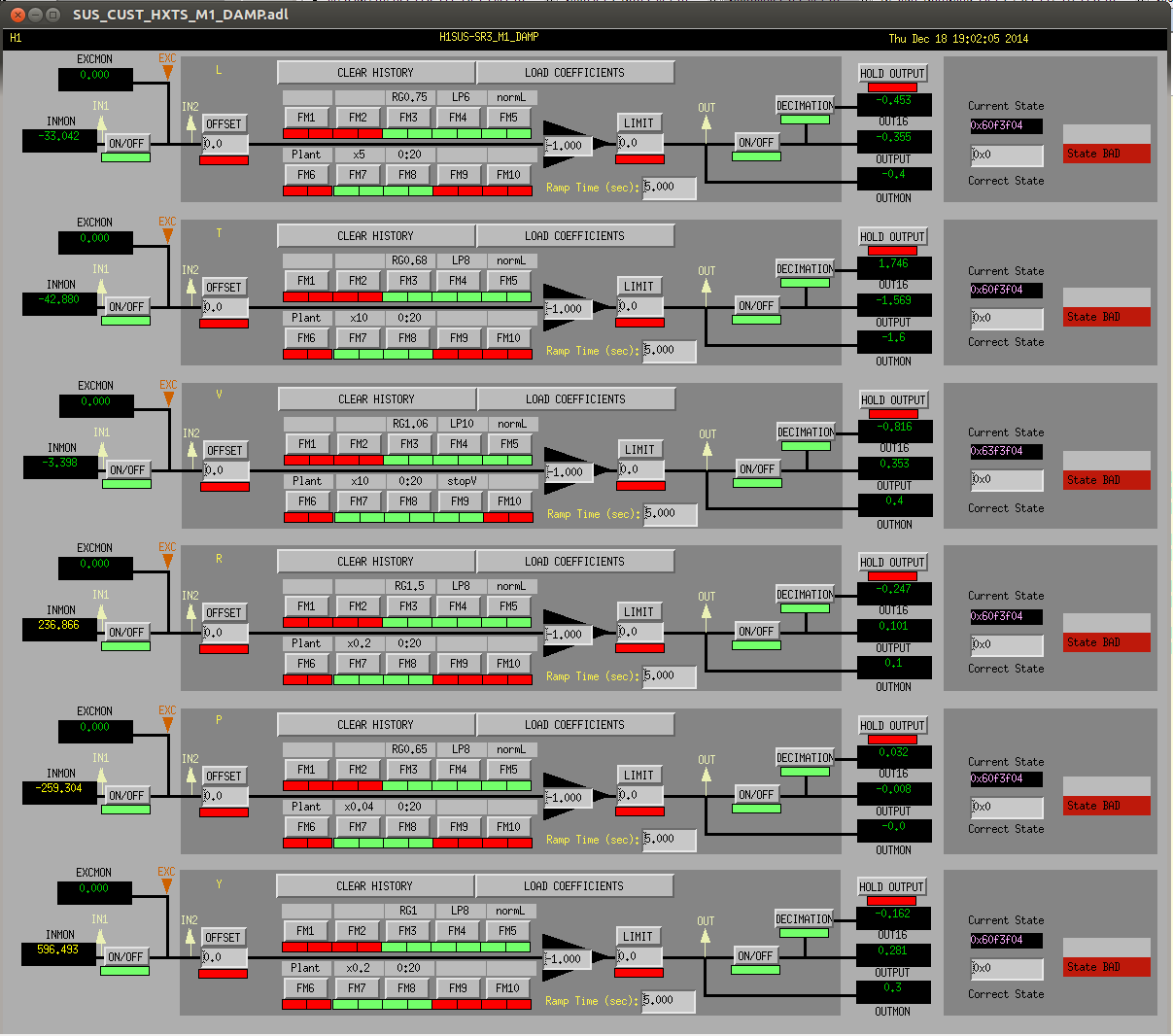
- page 6, I compare all units, in damping mode. HAM 3 looks fine.
- page 7, I turn ON the isolation on all units. HAM 3 still looks fine.
- page 8, I turn ON sensor correction on all units. The peak appears on HAM3.
- page 9, I turn off the Z sensor corretcion on HAM3. The peak is gone, but the X motion is much higher...
- page 10, I also turn ogg the Z sensor correction on HAM2, to verify it has no effect in the X direction for this "good" unit.
- page 11, I put HAM 2 and 3 vertical loops in high blend (Z, RX,RY), and turn off the sensor correction. HAM3 is fine.
- page 12, I turn on the sensor correction (X,Y,Z), HAM3 shows a slight peak at 1.2 Hz.
- page 13, I put Z back in low blend (01_28), sensor correction is still ON, HAM3 is still fine.
- page 14, I put RX and RY in low blend (250mHz), HAM 3 looks fine. So the problem shows up only with certain combinations of sensor correction and blend filters.
- page 15, I put RX and RY back in the standard 01_28 blend configuration, the peak at 0.6Hz is back...
- page 16, I repeat the test in page 14 (using 250 mHZ filters on RX and RY), the peak is gone again....
So at that stage I started to check loop shapes.
- page 17, I checked the blends installed. All seem fine. 0.6 Hz turns aout to be frequency where the CPS complementary filter crosses unity, but I think it's just a coincidence.
- page 18 to 22, I checked the open loops. Rx seemed to have a drop near 0.6 Hz. But the measurement was not repeatable, as shown in page 23 which looks fine.
- page 25, 26, I check the super-sensors. They don'y look nice at 0.5 Hz, but it may not be related.
Did not find anything abvious in the loop shapes, so back to sensor noise hunting:
- page 27, HAM 3 in damping mode. No problem in the local sensors.
- page 28, back to standard config (01_28 blends, and sensor correction...) , we can see the peak at 0.6 Hz in most local sensors.
- page 29, I put RX and RY of HAM3 in high blend, the peak now shows up at 1.12 Hz.
Summary:
the problem really depends on which blend filters are engaged for RX and RY. Depending on the blend filter used, the peak can show up at .6 Hz (using 01_28), 0.12Hz (high blend), or very little (using 250 mHz). THis set of blend filters however is too agressive at low frequencies. Despite the measurements we have performed today, it is still difficult to assess wheter this a a CPS issue, a mechanical issue, or a loop issue. We keep investigating.

I came back late to the lab and found the same problem. In order to take some measurements I set the IMC WFS gain to zero. The IMC was stable after that.