(To know the whole story about the Z-RZ coupling, see DCC document #E1400432.)
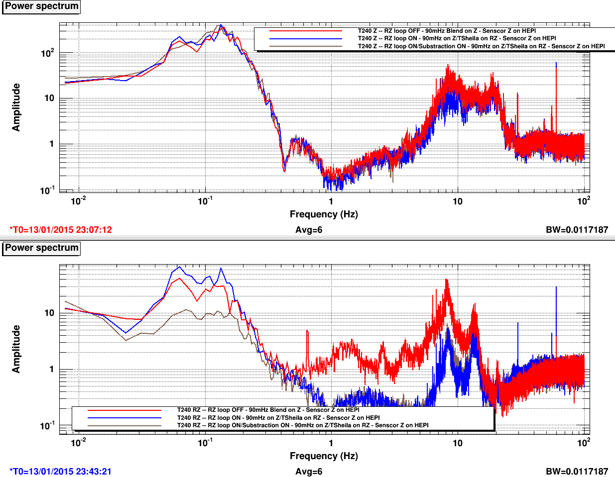
I turned ON the substraction on ETMY-ISI ST1 with good results. If you look at the first attachement:
- Red curve -> nominal configuration (RZ loop OFF)
- Blue curve -> RZ loop ON. As expected, we amplified the RZ motion around 0.1Hz by turning the loop ON. The loop provides some isolation above 0.5Hz. Z doesn't change.
- Brown curve -> RZ loop ON + Substraction ON. We can see an improvement by almost a factor of 10 in the RZ spectrum around 0.1Hz. The substraction seems to work just fine.
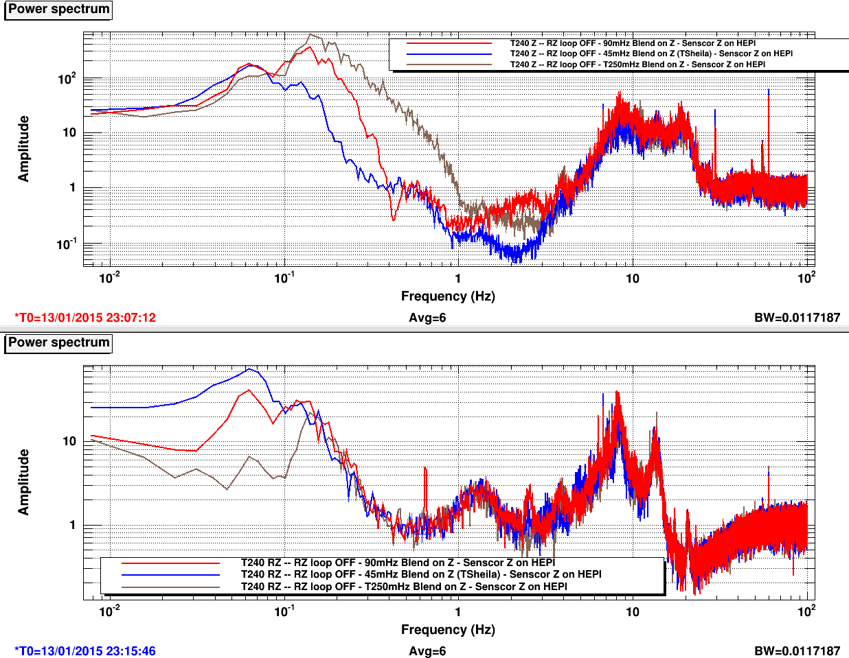
As Ryan suggested, we also wanted to see if we can obtain similar results without the substraction. We do have Z sensor correction on HEPI, so we might be able to relax the actuation on Z (meaning higher blend) and still have reasonable performance in vertical. By relaxing Z, the couping with RZ should be reduce. Unfortunately, the Z motion seems to big for our need if we swich to higher blend (see second attachement).
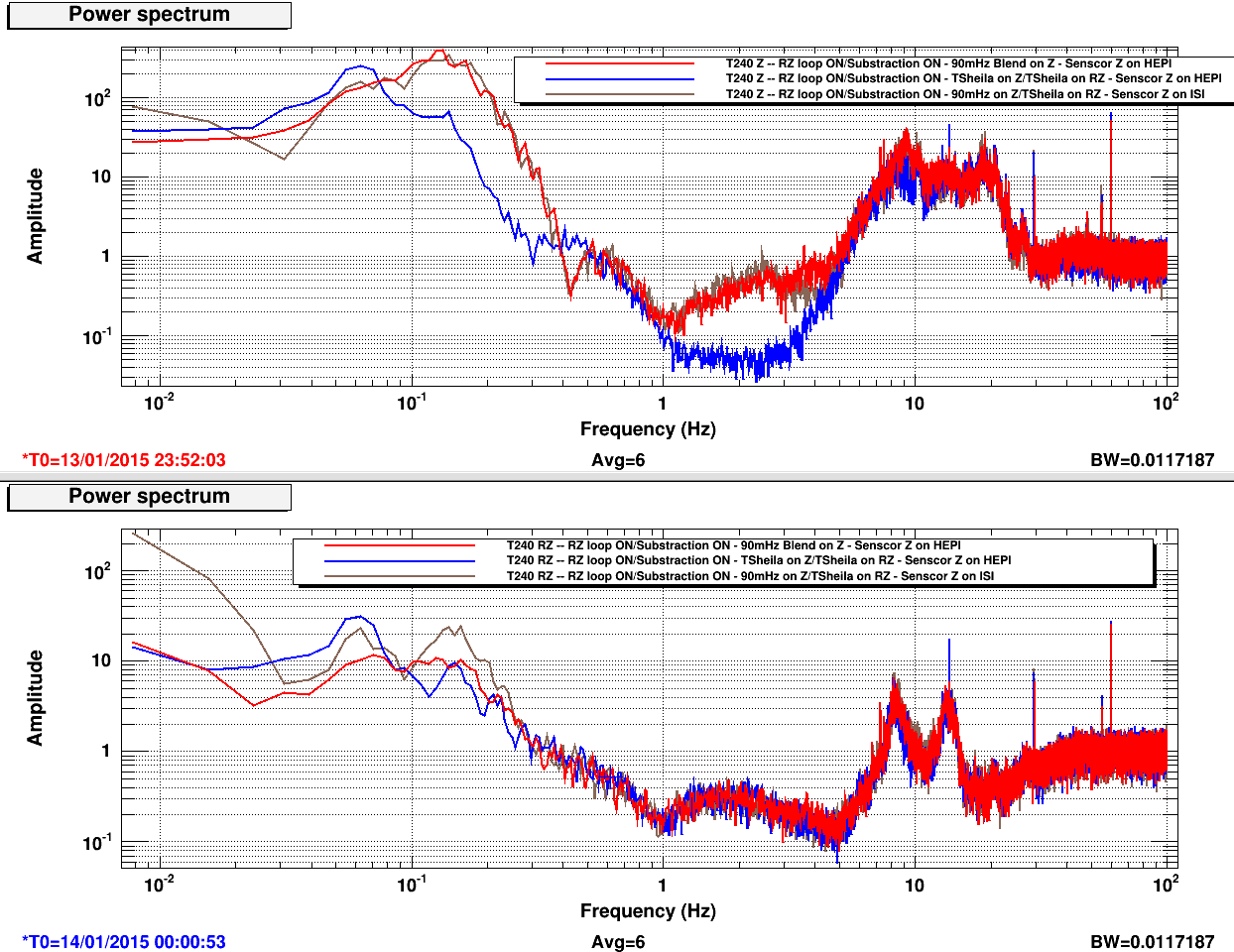
Last attachement shows different substraction configurations:
- Red curve: Substraction ON with a 90mHz blend on Z and Z sensor correction on HEPI
- Blue curve: Substraction ON with a 45mHz blend on Z and Z sensor correction on HEPI
- Brown curve: Substraction ON with a 90mHz blend on Z and Z sensor correction on ISI
Viewing those results, it seems that switching to a lower blend on Z might be a good idea.
For further analysis, we need to look at more sensors and the optical lever. We might want to look at the other chambers as well.


restarted h1iscey model, looks like it wasn't started completely due to obsolete wiki restart instructions.