jeffrey.bartlett@LIGO.ORG - posted 09:35, Friday 09 January 2015 (15960)
08:30 Meeting Minutes
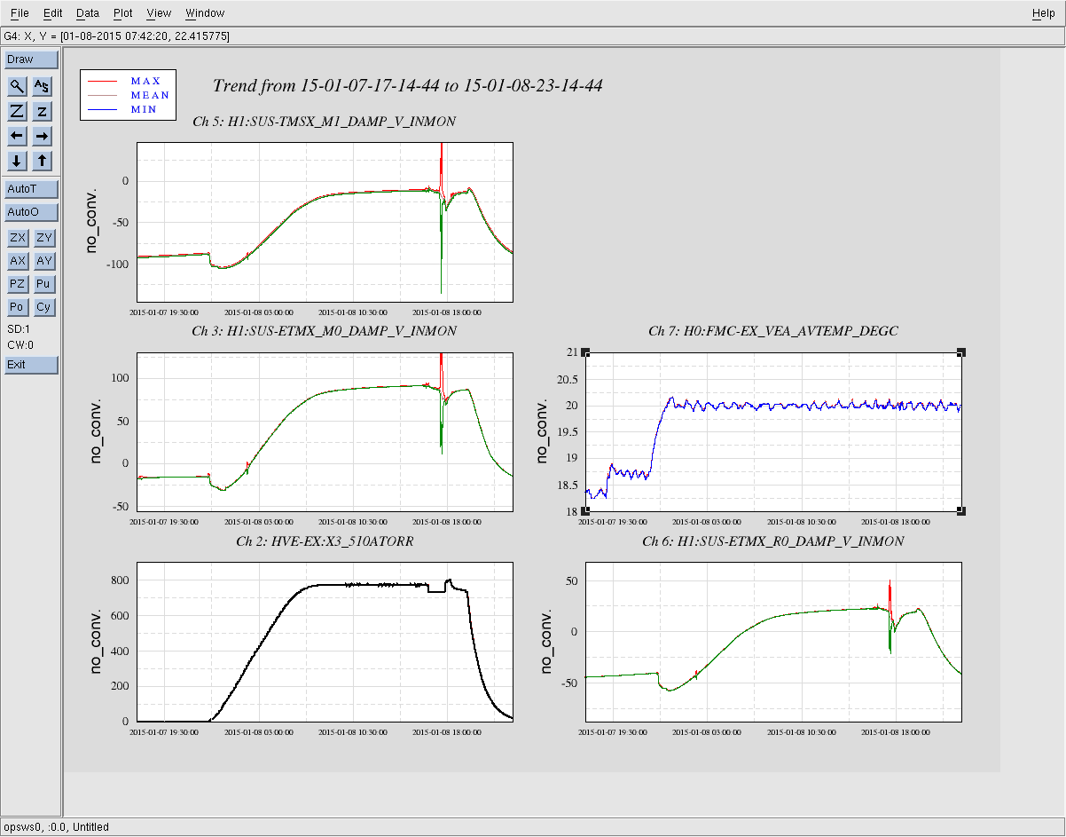
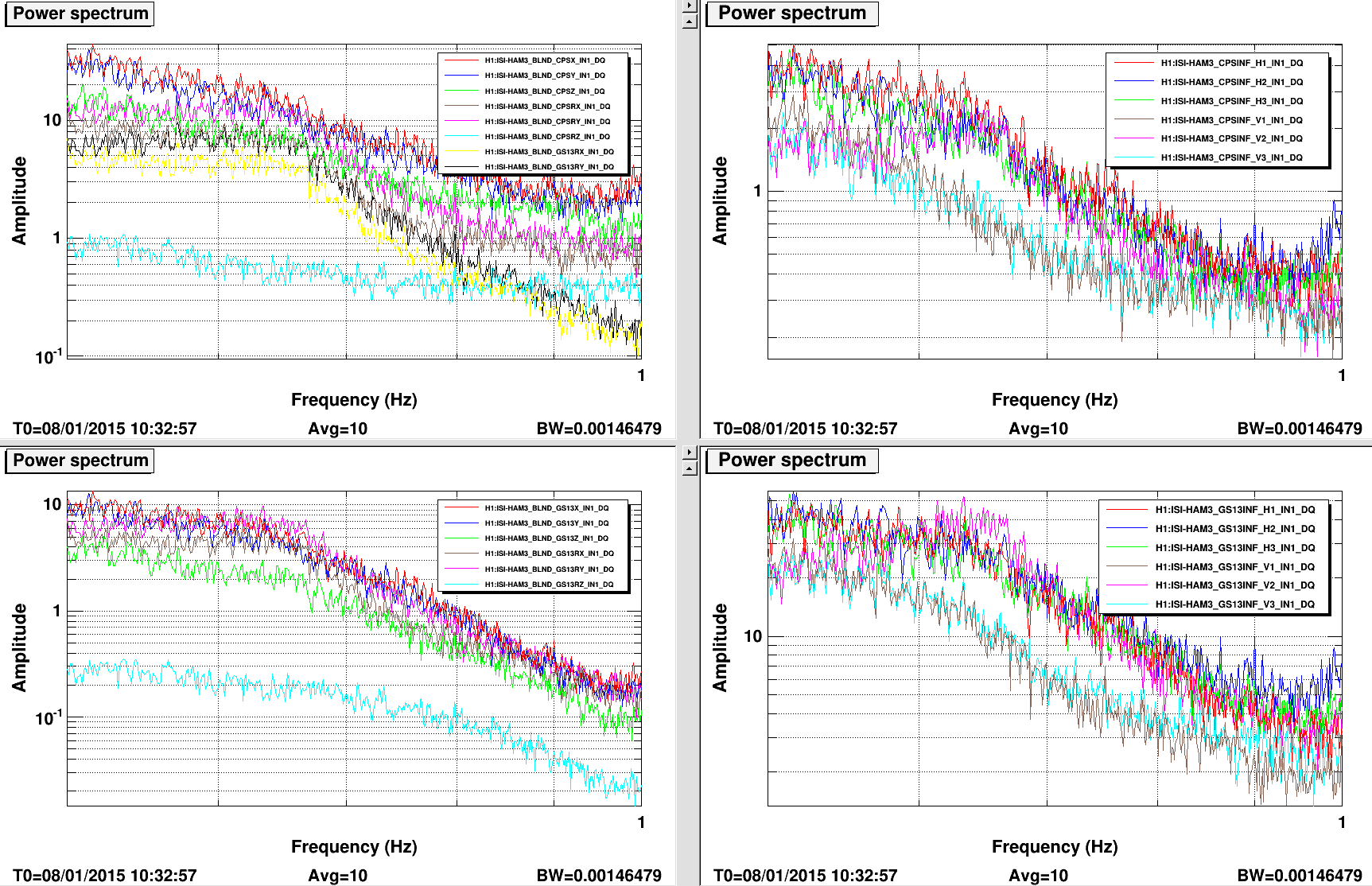
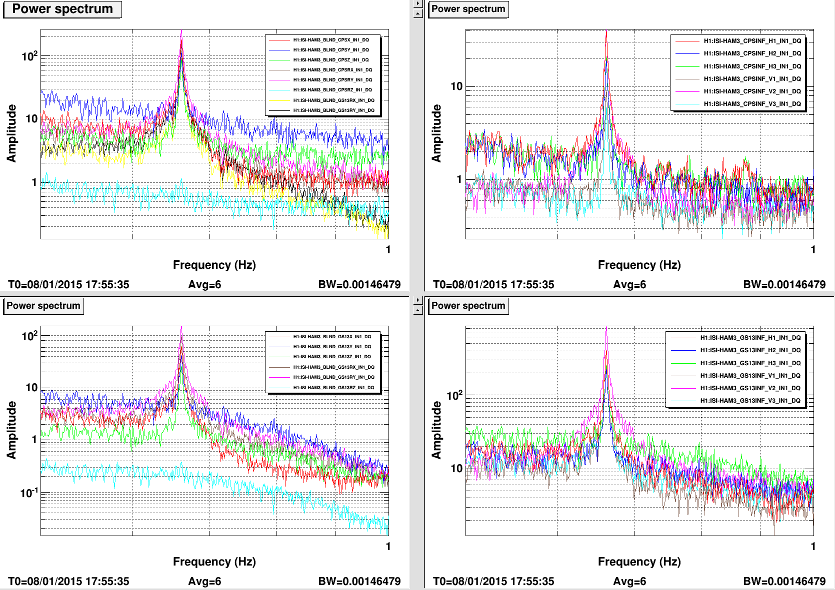
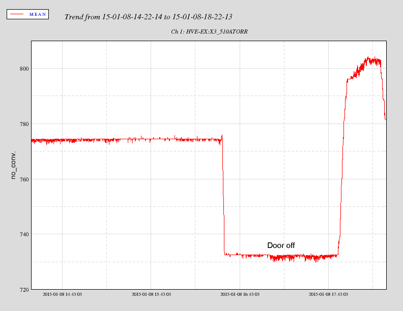
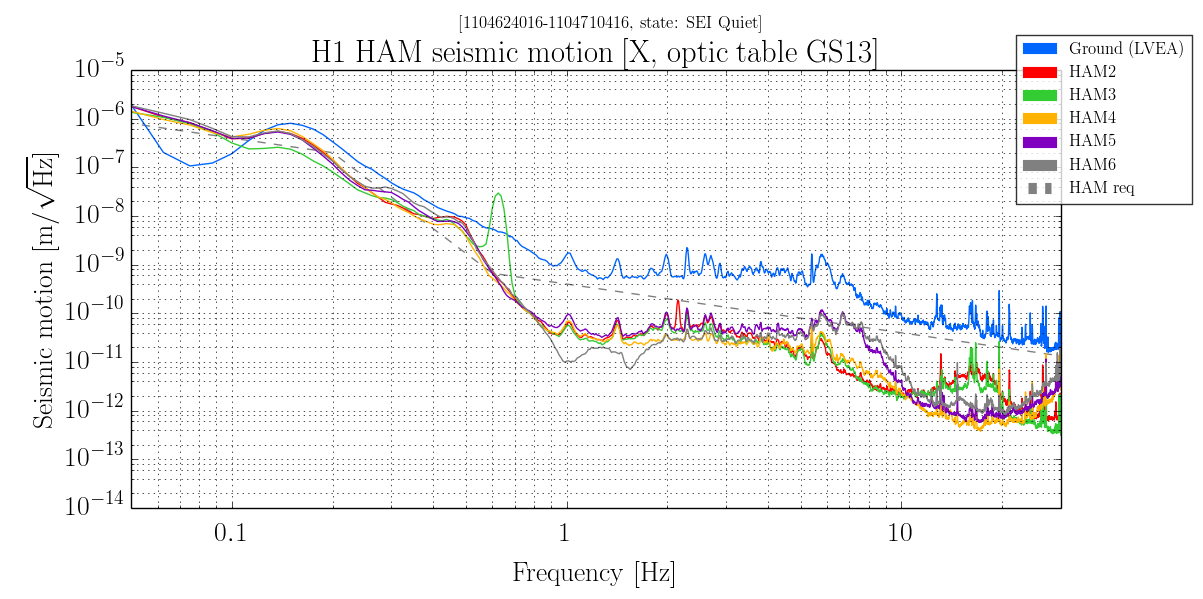
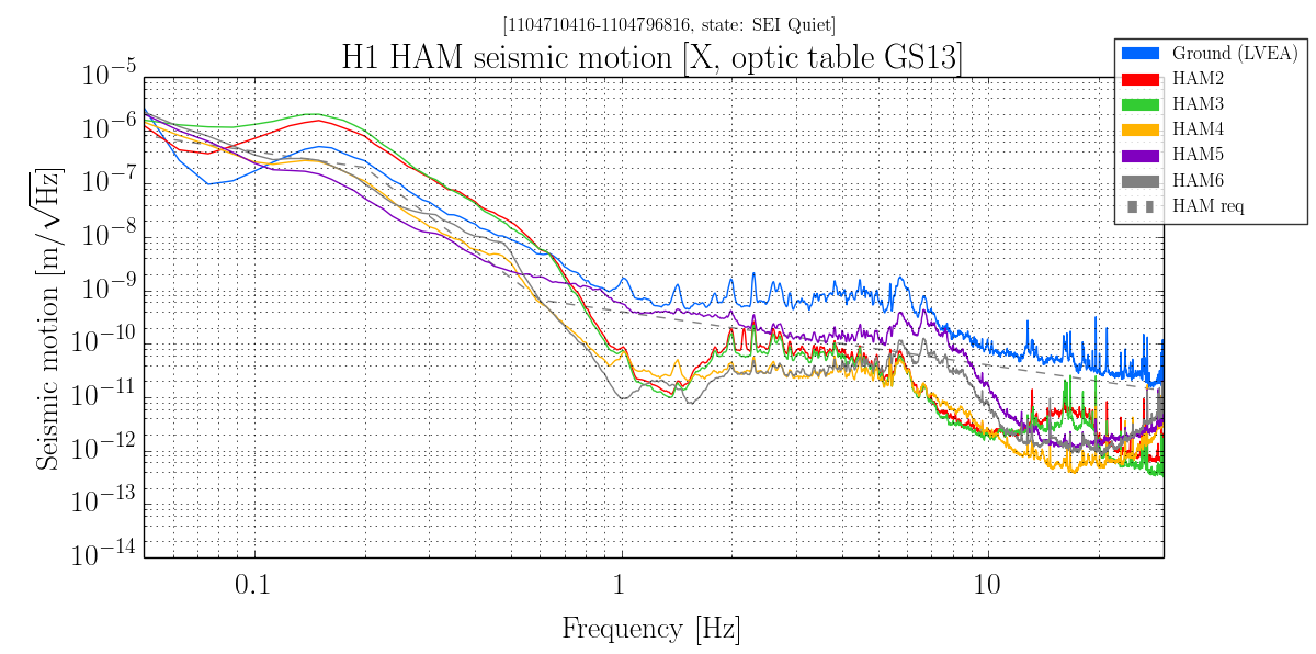
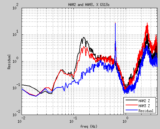
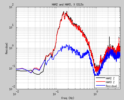
Seismic:
Working on HAM3 sensor correction problem.
3IFO HAM storage retrofit prep work.

Suspensions:
Check out of ETM-X after vent for EQ stop work.
Brett working ESD charging scripts.

PCal:
Software upgrade at End-Y.
Calibration work at END-X; End-X will transition back to laser hazard.

Commissioning:
Will be enforcing stricter limits to LVEA access and work during the afternoon.
All persons entering LVEA or end stations must check in and out with operator.

3IFO:
Rodica and Jodi working on finding 3IFO parts and sorting optics.
Work continues on removing the H2 test stand electronics from LVEA.