bubba.gateley@LIGO.ORG - posted 09:28, Wednesday 17 December 2014 (15673)
Instrument Air Compressor@ MX
The #1 instrument air compressor was changed out at Mid X yesterday afternoon.
The #1 instrument air compressor was changed out at Mid X yesterday afternoon.
no restarts reported. Conlog frequently changing channels report attached.
No evidence this morning, almost 24 hours.
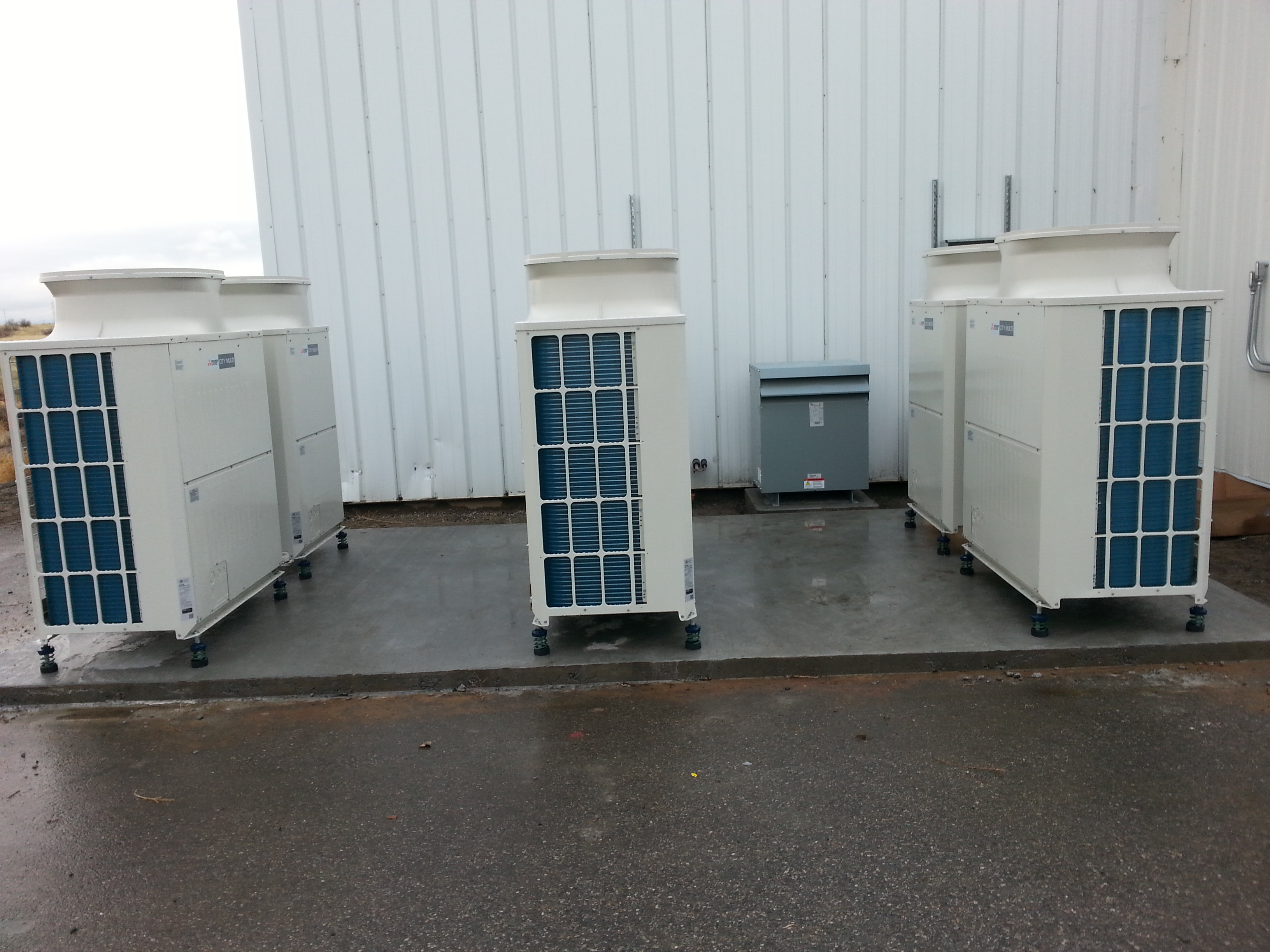
The outdoor units and transformer for the DCS addition are set in place. The partition wall is taped and ready for paint.
Elli, Sheila, Kiwamu,
We went in the HAM1 chamber this afternoon and completed the following tasks:
The HAM1 is ready for the door to be back on.
(Some notes)
We aligned the POP beam onto the diode when the PRMI was locked on the sidebands, 10W. The beam was visible on a laser card so that it was not a difficult job (though we had to spend sometime trying to re-acquire the PRMI lock). I steered the picomotor that was in front of POP_A to center the beam. After we coarsely adjusted the mirror, we then did a fine adjustment by looking at dataviewer and brought the beam to the center of the PD. This was done by locking a simple Michelson as this was easier to lock and bright enough to see the POP DC signal in the digital system. The beam dump was already in the designed position and I steered the reflection to the dump by rotating the POP_A diode, probably by 1 or 2 deg. Note that at the beginning, beam was barely hitting the dump.
Since none of the pico motors had the collars or kapton washers installed, we installed them this time. After the installation, three picomotors, out of four, still had a room of more than 5 mm in the thread. The last one in front of POP_A had approximately 2 mm in the thread both pitch and yaw. We opened and closed both REFL and POP beam diverters to make sure that they don't easily get stuck. We did 5 or 6 times of open/close operations and they did not fail.
After we finished the in-vac work, we realigned the PRMI and locked it on the sidebands. We confirmed that the POP was still receiving the light.
Kiwamu, Stefan
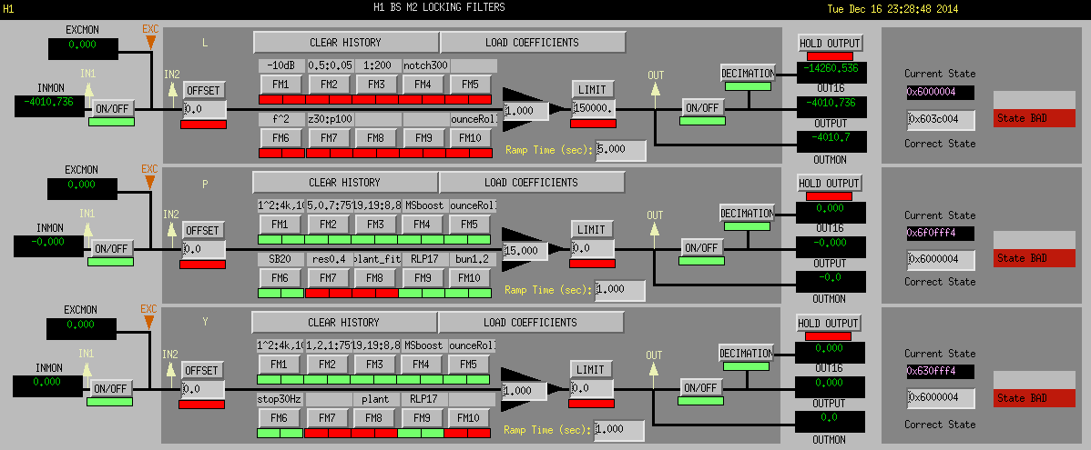
Tonight we copied the BS OPLEV filters to the BS M2 LOCK pitch and yaw filters, and modified them slightly to get some moderate DC gain on top of a significant suppression at the optics resonances.
- The modification we made is
PIT and YAW: FM1: zpk([0],[100],1,"n") was replaced with zpk([0.1;0.1],[4000;100],0.2,"n") . Together with the WFS filter bank (a simple 1/f integrator) this results in very weak DC feed-back.
PIT: We added a 1.2Hz resonance peak compensation and a p0.1:z1.5 low frequency boost to FM10:
zpk([0.02+i*1.2;0.02-i*1.2],[0.200028+i*1.18338;0.200028-i*1.18338],1,"n")* zpk([1.5],[0.1],15,"n")
The results in a reasonable secondary UGF crossing.
Pitch was tested, and resulted in a unconditionally stable loop.
Yaw wasn't tested yet. A snapshot of the engaged filters is attached.
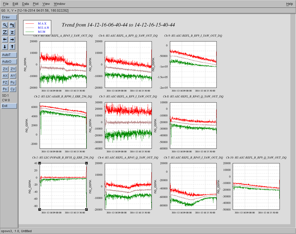
Also, from this morning's lock, here are some WFS signals that show clearly what is running away.

REFL_B_RF9_I seems to be the prime candidate.
| RF Input Power | Peak Height measured with OSA relative to noise floor | Modulation Depth | |
| 45 MHz | 21.5dBm | 79.2mV | 0.284 |
| 9 MHz | 17.27dBm | 41.2mV * | 0.205 |
| RFAM | RFAM/PM | |
| 45 MHz | 1.146e-4 | 4.0199e-4 |
| 9 MHz | 1.486e-3 | 7.233e-3 |
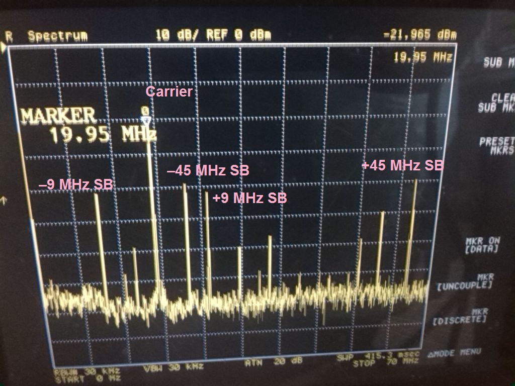
I annotated the scope screenshot from alog 15639 with carrier and sideband frequencies. Just reading off the plot we have
| Frequency | Amplitude | Unit | Ratio | Γ |
|---|---|---|---|---|
| Carrier | –22.0 | dBm | 1 | — |
| –9 MHz sideband | –41.0 | dBm | 0.112 | 0.226 |
| +9 MHz sideband | –41.5 | dBm | 0.106 | 0.213 |
| –45 MHz sideband | –39.0 | dBm | 0.141 | 0.285 |
| +45 MHz sideband | –39.5 | dBm | 0.133 | 0.269 |
Taking the average and assuming a 0.5 dB reading error we have Γ = 0.219(12) for the 9 MHz and Γ = 0.277(16) for the 45 MHz sidebands, respectively.
Paul, Mackenzie, Alexa
We measured the RFAM again; this time after the MC (with the PRM misaligned). Paul and Mackenzie had already aligned the beam onto the AC coupled 1811 NewFocus PD on IOT2R (same specs as before). We blocked the auxiliary laser. Again we used a TPS 30324 to measure the DC signal at high impedance, and the Agilent 43958 Spectrum Analyzer to measure the AC signal. We measured 210mV at DC, and
| RFAM | RFAM/PM | |
| 45 MHz | 2.245e-4 | 6.762e-4 |
| 9 MHz | 1.121e-3 | 5.63e-3 |
The PM represents the modulation depth. We repeated Daniel's calculation but wanted to collect the numbers with the Spectrum Analyzer to reduce the error. So again, we had the aux beam phase locked to the beam on IOT2R. We measured the following:
| Freq | Amplitude | Ratio | Mod Depth | |
| Beat | 60 MHz | -22.8dBm | 1 | |
| + 45 MHz | 105 MHz | -37.96dBm | 0.174 | 0.348 |
| + 9 MHz | 69 MHz | -43.2dBm | 0.095 | 0.19 |
| -9 MHz | 51 MHz | -42.50dBm | 0.104 | 0.208 |
| -45 MHz | 14.5 MHz | -38.82dBm | 0.158 | 0.316 |
Taking the average we find. Gamma_9MHz = 0.199 and Gamma_45MHz = 0.332. This seems a bit high given our previous two measurements. I have used RFAM = 2 * (Vsb/Vcar). There is no sqrt this time because we are measuring the amplitudes; whereas the OSA measured the power. The PD has a BW of 200 MHz, but maybe we are approacing the roll-off. We tried locking the beatnote at a lower frequency so that we would not need to worry about the PD's roll off; however, we had trouble getting a clean lock even at 20 MHz which seemed to be fine yesterday. Paul will attach the raw data.
..and here are the data. It seems like we can even pick out sidebands of sidebands with this measurement technique.
Betsy, Travis, Rick
How today went:
We spent a few hours this morning working on the in-vac side of the new ESD connector termination checkouts.
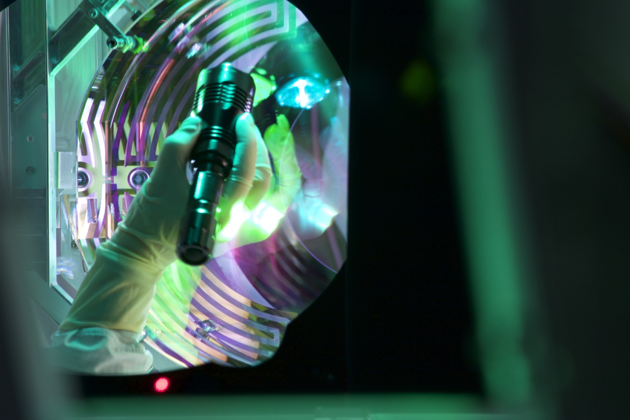
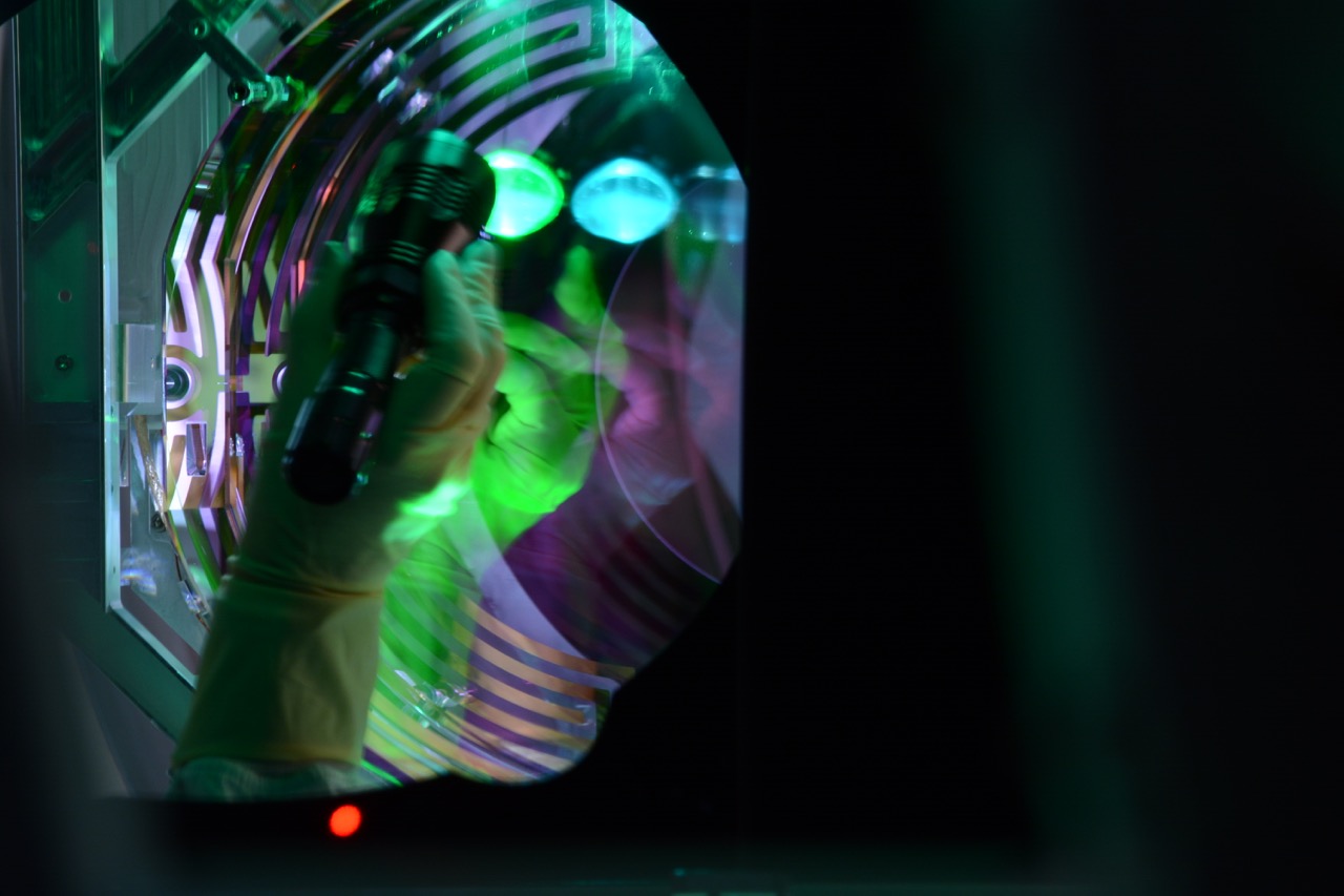
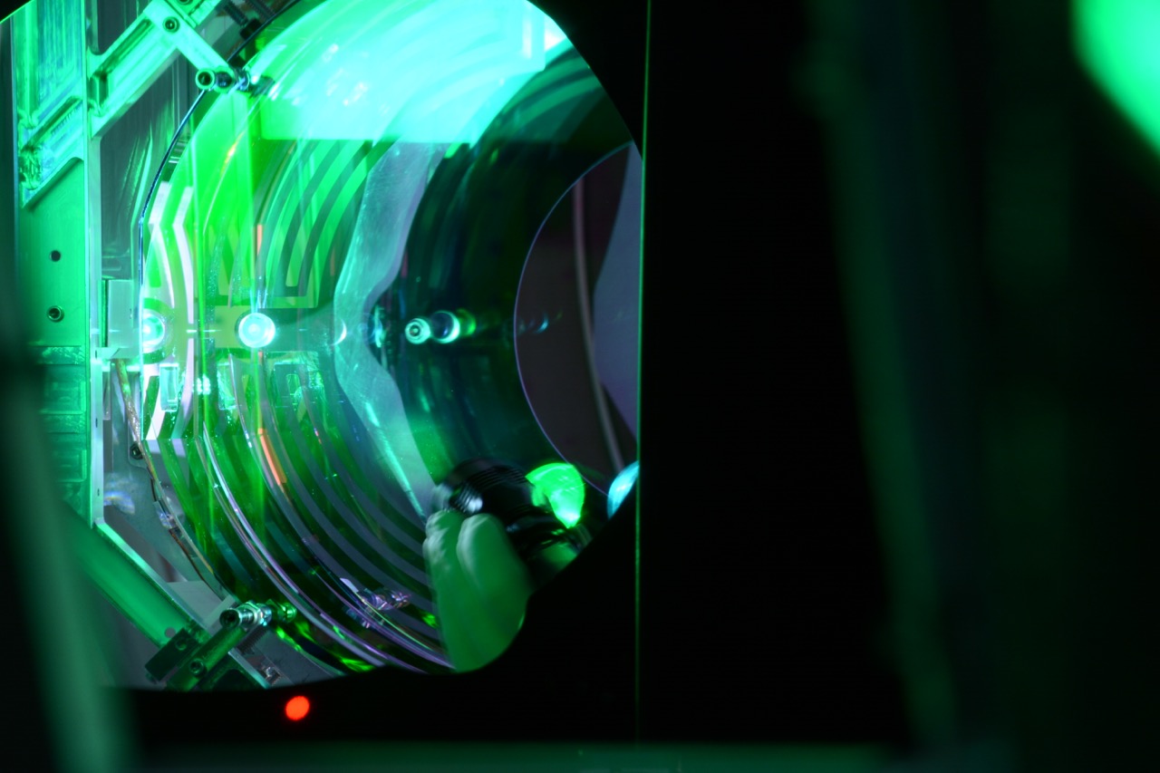
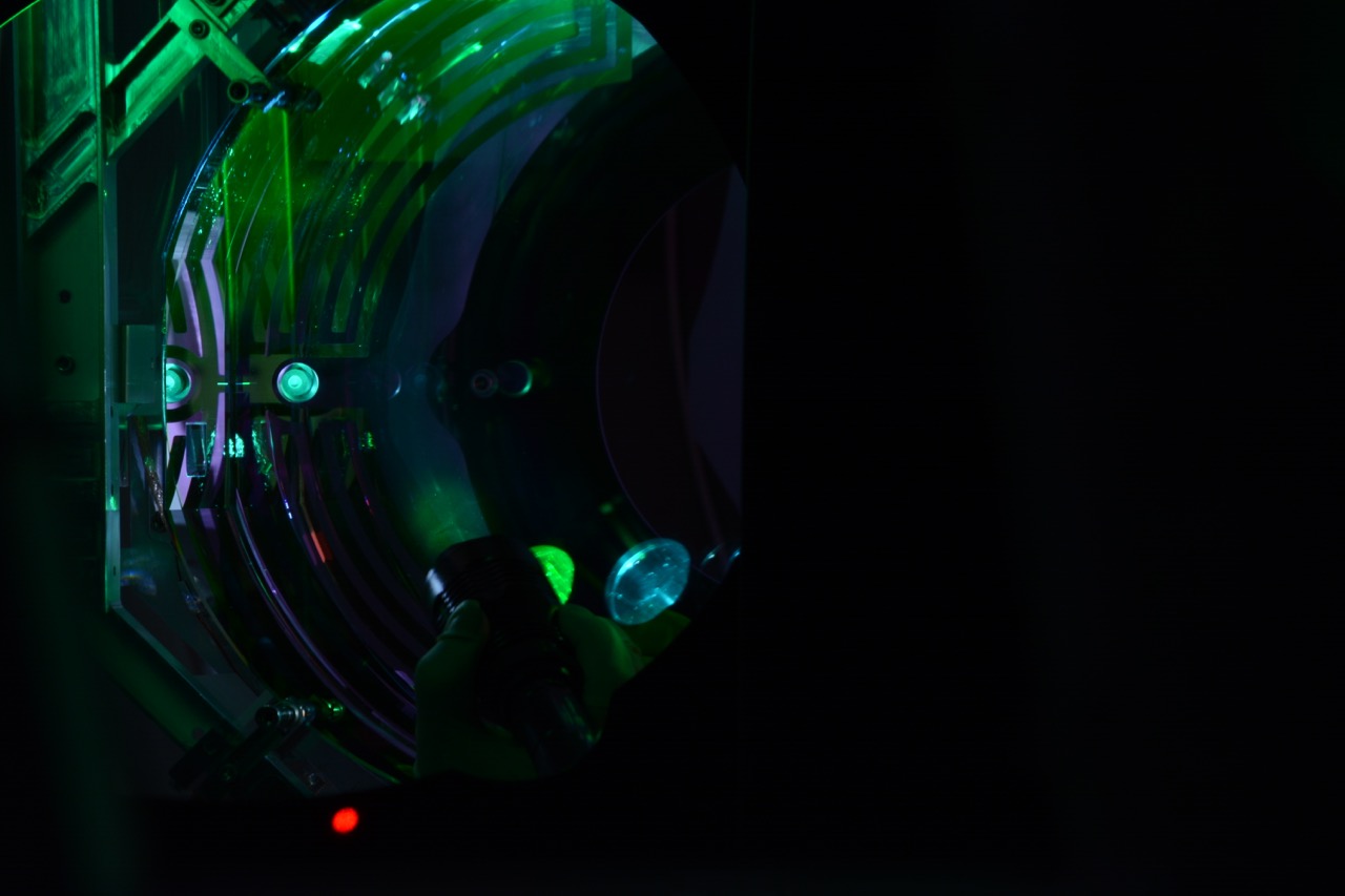
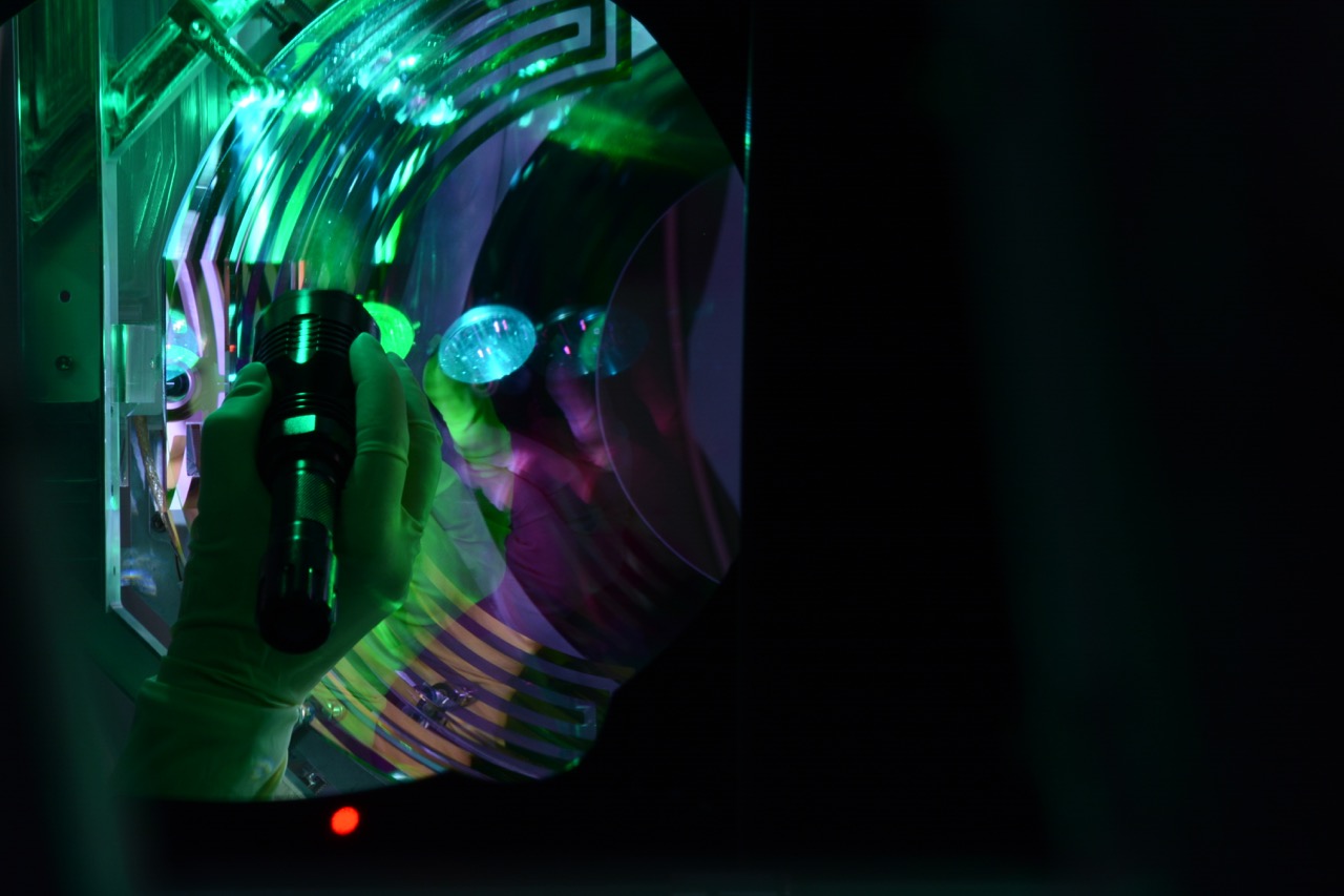
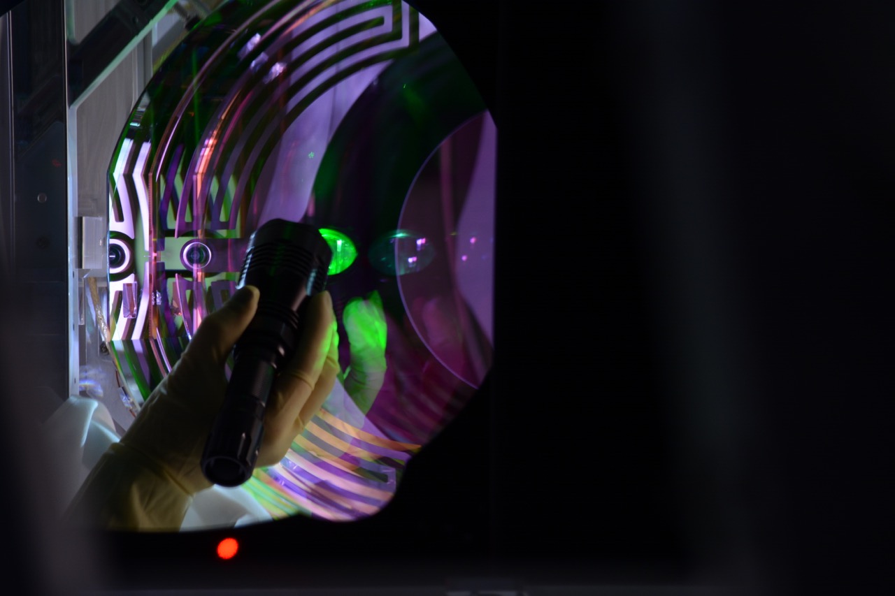
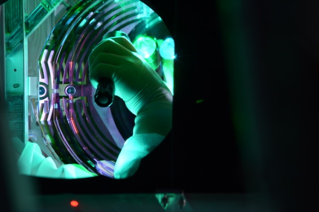
At ~2pm we pulled the FC sheet off of the ETMy-HR (painted on last night). We immediately saw that the 3 larger FC remnants that were causing all of the glint in the cavity arm were removed. Yay! However, it was also immediately clear (with the green flashlight) that the 3" ring feature and mottled haze were still there.
We took a break at 3pm and spoke to a wider SYS+ audience where it was determined we would attempt to do a test drag wipe on the mottling nearer the edge of the optic. We worked on getting pictures of numerous mottled areas in the haze of the donut shape on the ETMy-HR before doing some test drag wipes. Then we chose an area toward the top of the optic where there was another relic IAS window circle print near the 12 o'clock position to test drag wiping. After numerous failed attempts at performing the light-duty friction-only drag wiping technique on this area I resorted to folding the lens wipe a few times and applying pressure during the drag wipe. This made a smudge where I wiped which I then had to spend another ~5 wipes removing. We then reevaluated the mottling and found that we might have improved it in one small place, but not the entire area I had been working on. We then redirected a streaky area at the bottom of the optic to see if I could get a better technique down. No such luck and I again had to resort to applying pressure numerous times in order to see an improvement. Since we had better pictures of the 12 o'clock position mottling area that I had been working on earlier, we decided to revisit that area. I again made an attempt at friction-only drag wiping of this top area. In the process I must have lightly swiped the optic with my glove because when inspecting the optic after the drag wipe, we found a ~2mmx2mm patch of particulate just outside of the 3" ring near the center of the optic. Brilliant. We also found more particulate on the optic from the waving lens tissues. We tried to blow them off with a few minutes of N2. This did not seem to work. One of the particles was quite large and even a light dab with an swab did not move it (in fact, ~5 attempts to snatch it off via dabbing failed). Rick captured a few pictures of the "new" features.
At this point we aborted the drag wipe testing and carefully repainted FC back on. I was very careful to not brush across the large particle nor the "patch" area very much. I applied very thick ~1 inch long strokes which at first were more like dabs near these areas. (All other saturated sloppy strokes were ~1-2" in length, repeated.)
I do not think we can drag wipe the full surface (or even the central ~8") of the ETMy-HR. We were not sucessful in ~25 attempts to get a good pull on the optic except for in the localized areas I mentioned above when I used finger pressue. And after these attempts we added contaminant to the surface by accident.
The optic size obviously makes it hard to work with. The working area is too small for 2 hands, elbows, flashlights, your head, etc. Then, the task is too hampered by suspension brackets and braces to get good surface tension with the flat lens tissue. The wipe wants to continue to pull off the surface and ripples easily. As well (or worse), we had a hard time getting the wetted wipe to the surface before the acetone dried.
Rick plans to attach some pictures to this alog so check back later or tommorrow.
Some images to supplement Betsy's narrative.  Hopefully the file names are sufficiently descriptive.
For visualizing some of the features, zooming helps a lot.  Look in the elliptical area illuminated by the green flashlight beam.

Filenames, in order, are:

LHOyTopLineBeforeCleaning176.jpg

LHOyTopLineBeforeCleaning185.jpg

LHOyBirdsHeadBrightEdge180.jpg

LHOyDarkBirdsBeak181.jpg

LHOyLongVerticalBrightPatch182.jpg

LHOyGloveTouchPatch186.jpg

LHOyTopLineAfterCleaning190.jpg
 (Doug Jason)
The HAM5 oplvr mirror must have been bumped in situ as we were unable to get the reflected beam out of the viewport to the receiver. It is far enough off that the reflected beam cannot be seen hitting anywhere. We will need to adjust it with the next vent opportunity.
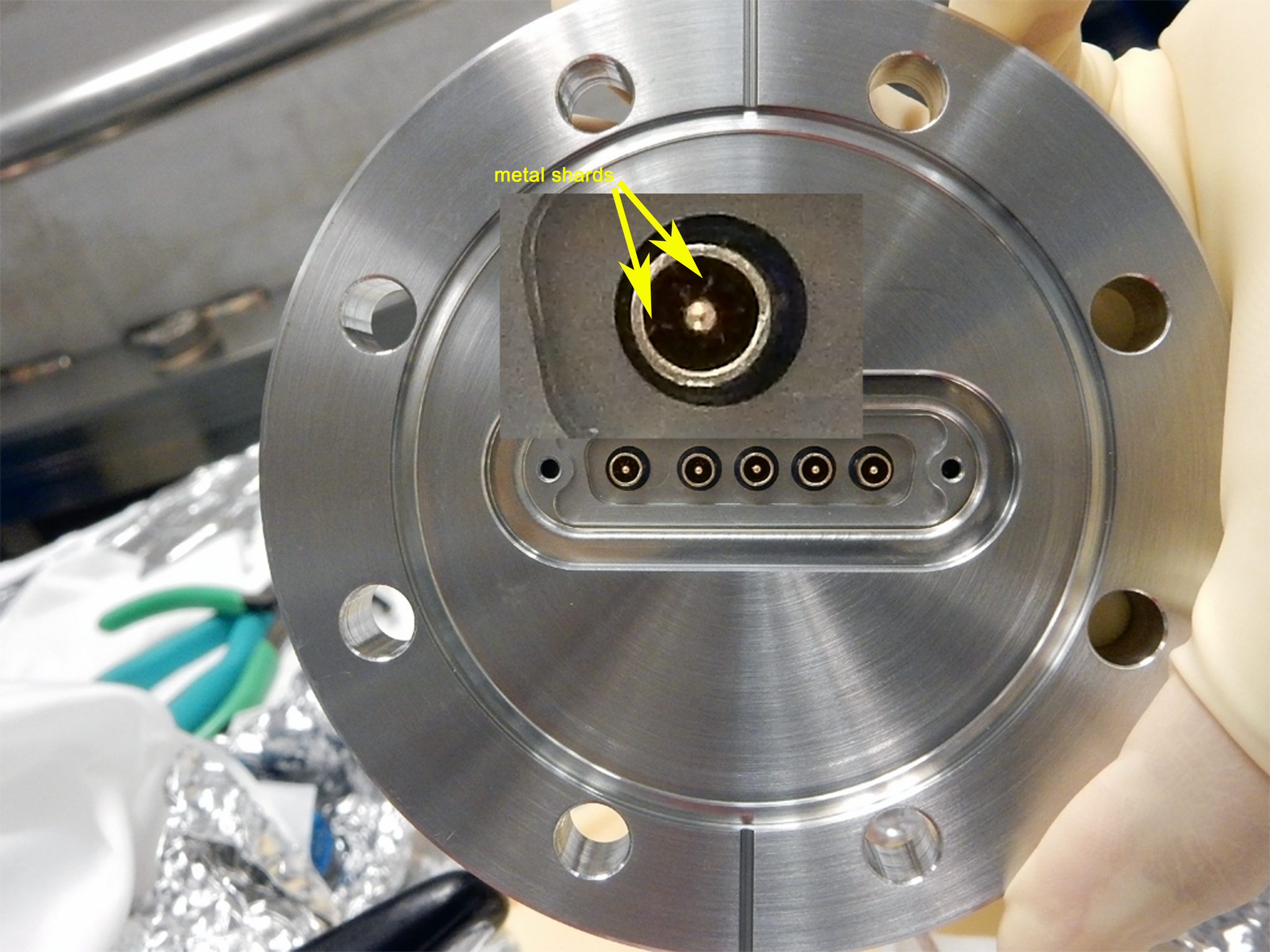
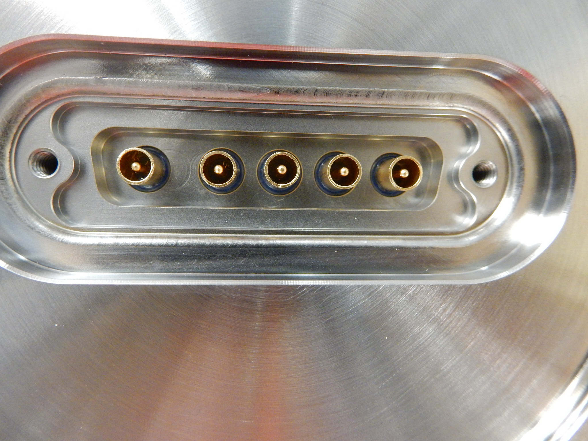
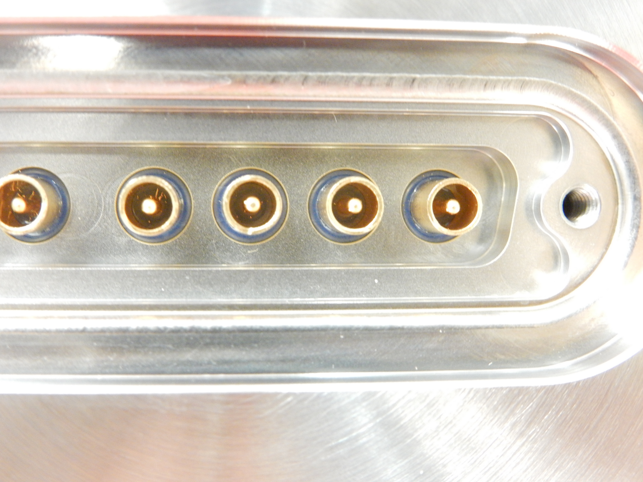
Betsy, Filiberto, Gerardo, Richard, Travis

1. The old vacuum feedthrough was removed by Gerardo
2. Continuity test were done on each pin to verify each section LR, UR, BIAS, UL, and LL.
3. The in-vacuum cables were re-terminated for installation of the new UHV 5-way coaxial connector.
4. Gerardo installed new feedthru (has not been leaked checked).
5. In-vacuum and in-air cables were connected to feedthru.
6. All pins were HIPOT to 1K and passed (some pins had to be reterminated).
6. Pin layout for ESD is as follow:
   Pin 1 - LR
   Pin 2 - UR
   Pin 3 - BIAS
   Pin 4 - UL
   Pin 5 - LL
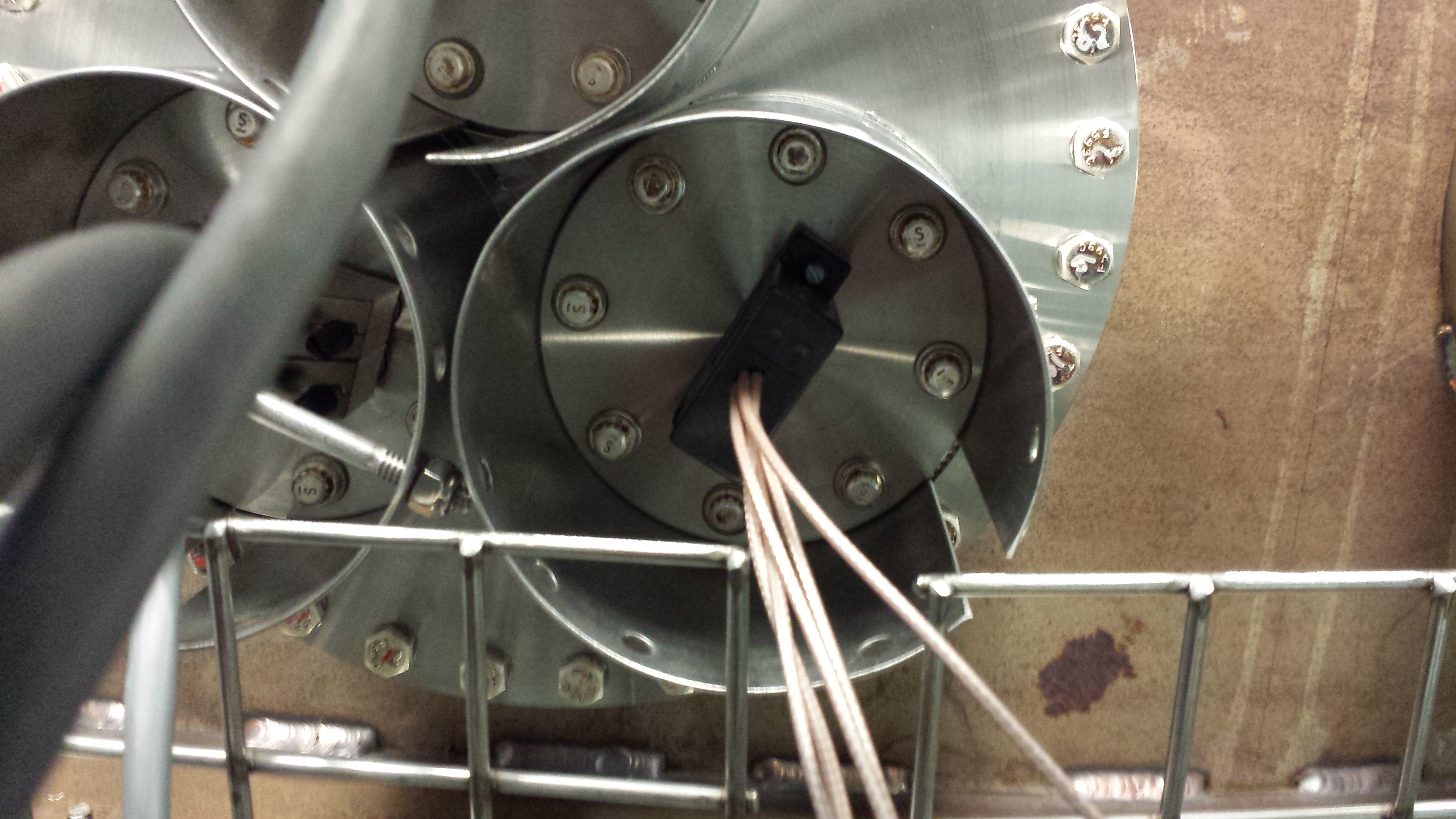
Fil, Gerardo, Richard, Peter

Attached are 3 photos of the flange that the replacement ESD connectors mate to.  The first image (ESD1.png)
shows some metal shards in the first two pins sockets from the left.  They can be clearly seen in the following
images.

Some of the connections passed the HiPot tester only to sometimes fail when retested.  Some of the connections
that had previously failed, passed.
LVEA: Laser Hazard
Observation Bit: Commissioning

07:00 Karen & Cris – Cleaning in the LVEA
08:01 Kyle – Soft close on GV5 & GV7. Prep work for door removal of HAM1
08:10 Kyle, Gerardo, Bubba – Removing door on HAM1
08:15 Hugh – Working on CS HEPI system
08:20 Hugh – Taking down HEPI pump in LVEA mezzanine to fix leak
08:48 Aaron – Working on PEM power cables in LVEA
08:50 Filiberto – Going to End-Y to prep for ESD cabling
09:30 Hugh – Finished with HEPI work and out of LVEA
09:10 Peter – Going into the H2 PSL enclosure to take pictures
09:19 Doug & Jason – Going into the LVEA to prep for HAM5 OpLev check
10:24 Jonathan – Recycling 2F authentication system
10:36 Karen & Cris – Going to End-Y to deliver garb and clean
10:38 Betsy & Travis – Going to End-Y to work on cleaning ETM-Y
10:40 Filiberto – Going to End-Y
11:00 Add 200ml water to diode room chiller
12:28 Rick – Going to End-Y
13:08 Cris – Going to End-X to restock garb and turn on small cleanrooms
13:08 Karen – Going to End-Y to restock garb
13:30 Betsy, Travis, and Rick – At End-Y cleaning
13:35 Adjutant on site for repair work for Kyle
13:48 Sheila, Elli, and Kiwamu – Going into HAM1 to do alignment
13:54 Dale – Going to HAM1 to take pictures
14:50 Krishna & Fabrice – Going to End-X to work on BRS system
15:23 Travis – Going into the LVEA looking for Acetone
15:30 Rick, Travis, & Betsy – Going back to End-Y for more optics cleaning
15:48 Sheila – Transitioned LVEA to laser safe
Hugh, Sheila, Stefan, Elli, Kiwamu,
The mysterious IMC misalignment event happened again. We are speculating that there may be a loose optical component in the IMC refl path on the HAM2 in-chamber table.
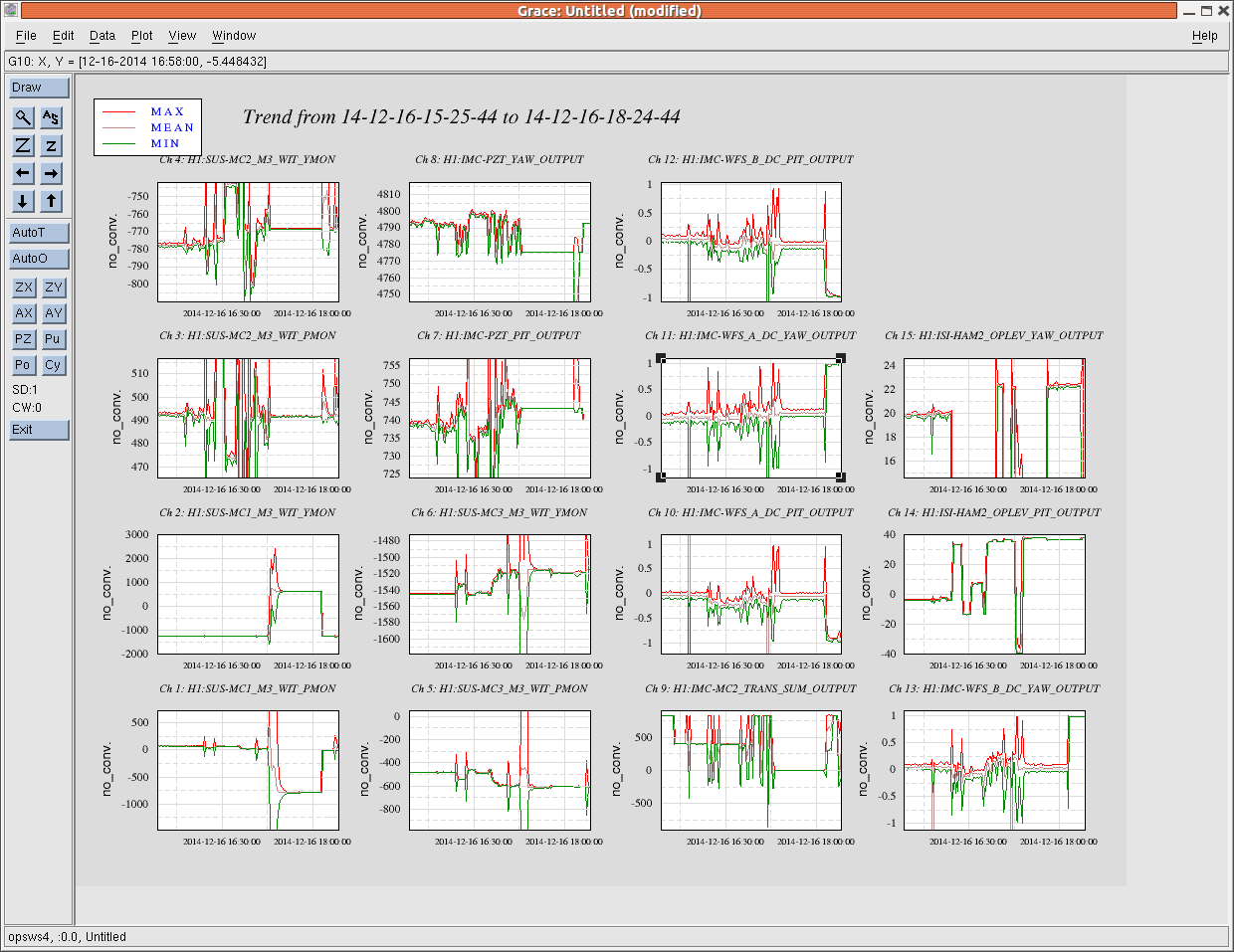
Back in the last February, there was a strange misalignment event in IMC (see alog 10335) where the IMC reflection path seemed to have significantly moved for some reason. This happened again this morning. This time, it was associated with the HAM1 activity of taking the door off from the HAM1 chamber. It tripped the HAM2 ISI and HEPI. After untripping them, we noticed that the IMC reflection was misalgined so much that the beam was almost missing the reflection camera and WFS diodes. However, like the previous event, the IMC power build-up was still reasonably high (it was at 820 counts in MC2 trans which is usually 830 counts or so) when it was locked. Sheila and Hugh then restored the HEPI back to the previous positions using the IPSs as a reference. At this point we could already see a reasonable DRMI flash at the dark port and also the IM4 trans seemed to have come back to the previous position. Based on these observations, we determined that the misalignment was only in the IMC refl path which is exactly the same conclusion as the previous event. So we realigned the refl path on IOT2L. Now IMC is locking fine and ASC loops were engaged without an issue.
In addition to those recovery activities, we did a brief test where we steered the HEPI by a big amount (~200 urads or so) in each rotational degree of freedom to see if we can reproduce such a big misalignment in the IMC refl, but we could not move the spot on the camera back to the center. Also, we quickly checked the mirrors in the IMC refl path on IOT2L to see if there is a loose component or something easily movable, but we could not find any. The misalignment was mainly in the horizontal direction on the table. The spot position on all three diodes (REFL, WFS_A and WFS_B) had almost the same amount of displacements horizontally, by half a cm toward the East. The attached is 3 hours trend of various sensors. At one point, both the WFSs got misaligned and at the same time the MC1 witness sensors saw a jump in both pitch and yaw (which I think is me untripping the HEPI and ISI).
Just to be thorough, I had also taken down the entire corner station HEPI to address a fluid leak. This took down all HEPIs and most ISIs--maybe the timing here was poor.
Also, "...realigned to the IPS...," we returned the Cartesian positions back to their pre break positions, not the individual IPS values persay. Still these moves were a few 10s of urads (we ignored the several um of translational shifts.)
Also as a reminder, HEPI only keeps the RZ dof, all others just servo to the free hanging position before the current isolation. Given the lack of impact of moving the HEPI 100s urads, letting it wander about a few 10s of urads each time it breaks isolation may be reasonable.
The leak at the electrical break was still leaking yesterday so I ramped down the pumps, loosened the hose clamps and shifted their position. Restart would have been faster but my medm was partially frozen giving live data readbacks but unresponsive button pushing. I mistakenly decided to restart the controller and still had an unresponsive medm. Medm would not restart and then restarting the AirBook was equally painful. Once it was restarted and I could get a fresh medm, everything came back easilly. While the pressures were down, recorded some pressure zero offsets for the database.
[Mackenzie, Paul]
Yesterday we had trouble getting a large enough beat signal between the aux laser and the main PSL. After discussions with Dave O., Stefan and Daniel, we were convinced that the aux laser was not operating monochromatically. This can apparently occur if the aux laser is close to a "mode hop" region when we bring its frequency close to the PSL frequency using the temperature control. We then end up observing the beat frequency between the PSL and one of the "parasitic" modes of the aux laser, which has a much smaller amplitude than the main mode.
On Daniel's advice, we adjusted the diode input current as well as temperature, in order to give us an additional frequency control option that affected the proximity to the mode hopping region differently to the temperature. After some searching around, we suddenly observed a forest of peaks, with one especially large peak.
This forest appears to have been a combination of a) saturation of the 1811 AC output exciting harmonics of the base beat frequency and b) contributions from RF sidebands of the PSL light. We reduced the power on the 1811 using the filter wheel (we ended up using the OD 2.5 filter), resulting in the spectrum shown in the attached figure. The VCO offset frequency was 20MHz. Interestingly, the beat between aux laser and 9, 45MHz sidebands are quite visible.
The dominant beat frequency now registers a -22dBm signal at the AC PD output on the spectrum analyzer, even with the power on the PD attenuated such that the DC output from the PD produced by the PSL beam is less than 1mV (the PSL beam is the weaker of the two beams at the PD). This may still seem a little weak, but it is much better than yesterday, when we had ~-50dBm AC on a ~100mV DC signal.
After some adjustment of the servo box gains, we were able to achieve stable PLL locks. There is no slow temperature servo path included yet, so the PZT on the aux laser will go out of range rapidly if the temperature dial is not adjusted by hand. By adjusting the temperature dial, it was possible to keep the PLL locked for tens of minutes.
Next, we switched the frequency reference for the PLL offset from the Marconi VCO to the swept sine output of the network analyzer. This presents a new challenge, because now not only does the aux laser have to phase lock to the PSL, but it also has to track the offset frequency generated by the NA. After playing around with IF BW, sweep ranges, source power etc., we were eventually able to get the aux laser to reliably phase lock to the PSL and track the NA frequency through a ~2MHz frequency range (almost enough for a full PRC sweep). We convinced ourselves that the PLL was locked and tracking the NA frequency by observing the TF from NA drive signal to 1811 AC output. When the PLL is locked, the TF is flat, high, and smooth, since the 1811 AC output is coherent with the NA signal at the same frequency. When the PLL is unlocked, the same TF is many decades smaller.
Each time the NA reaches the end of a sweep and flips back to the start frequency, the lock drops. I'm not sure there's much we can do about that. It would help to have the slow path enabled though, in order to compensate for slow drifts of the aux laser frequency away from the PSL frequency.
Next we plan to try some PRC sweeps if there is PRMI locked time available. For this, we will take the TF from NA drive signal to one of the REFL AIR broadband detectors, with the PRMI locked and the PLL locked. Depending on how that goes, we may pursue the slow temperature feedback development.
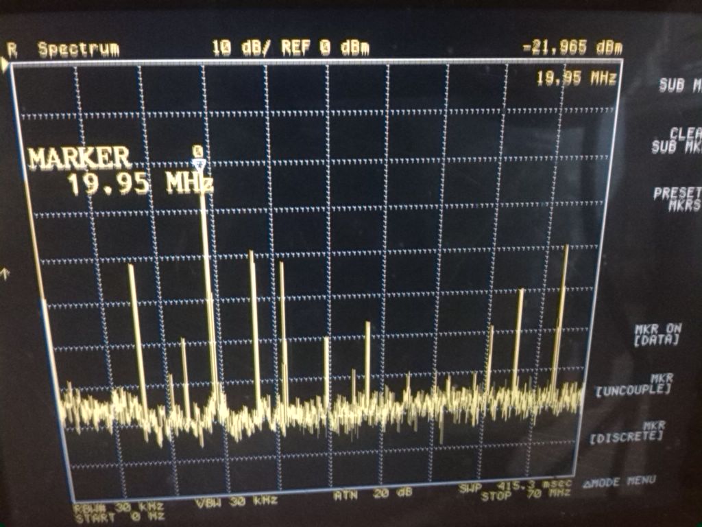
With a subcarrier you can measure the strength of each individual RF sideband---with upper and lower sidebands separated around the VCO frequency. The ratio you see here between RF sideband amplitude and carrier is a direct measurement of the modulation depth.
Great point, what a convenient way to measure the modulation depth! It's also probably a lot more precise that the OSA.
When we get the PLL going again later today I'll save the data from the spectrum analyzer so we can do a more careful analysis.

