Stefan, Paul, Kiwamu,
Tonight, we conitued working on the PRMI carrier lock. It is getting stable again.
(PR3 DC-coupled oplev servo)
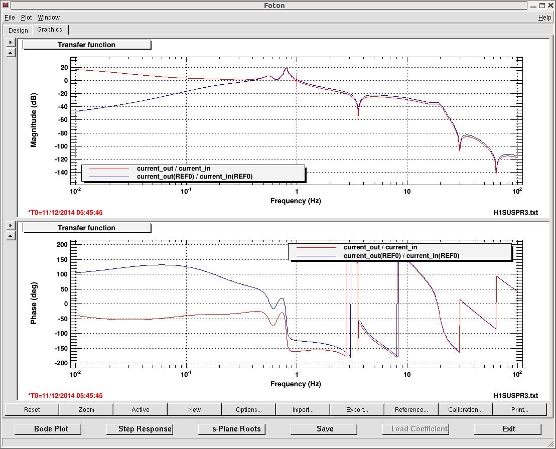
Locking the PRMI, we immediately noticed PR3 drifting, which resulted in lock loss in a few minutes after lock is acquired. This is something we already knew (see for example alog 13837). First, we decreased the PSL power to 5 W in order to reduce whatever the thermal effect on PR3. Then we worked on the oplev servo on PR3 to pin it down on a certain angle. Since the PR3 opelv loop had been modified to be AC-coupled (alog 14719 from this past October), we put it back to DC-coupled again. This was done by adding some zero-pole pairs in the existing M2 stage damping loop. The DC couepling filter now resides in FM9. See the attached for the new DC-coupled filter. The blue curve is the original AC-coupled open-loop TF and the red is the new DC-coupled one. Note that the overall gain in the plot is not adjusted. The DC-coupled PR3 oplev gave enough stability that we can then work on some ASC loops.
(ASC loops)
We then closed two ASC loops in order to maintain the PRMI at high build up. Currently we engage the follwoing loops; AS_A_45Q -> MICH and REFL_B_9I -> PRM. Since we have already setup the control filters and suspensions, we simply changed the input matrix without chainging the servo gains. Here are the input matrix elements that we used:
-
AS_A_RF45Q_PIT = -10
-
AS_A_RF45Q_YAQ = -5
-
REFL_B_9I_PIT = -0.3
-
REFL_B_9I_YAW =-0.1
This gave more stable lock which could last more than 30 minutes. Most of the lock loss was due to just us trying to make some changes in situ. Also, we needed to engage the BS top mass length feedback in order to keep it for many minutes because of high seismic.
(BS oplev glitching again)
Even with the ASC loops engaged, the ASDC fluctuated a lot. It could fulctuate from 4000 counts to 40000 counts at low frequencies below 1 Hz. Apparently the low frequency signal was associated with some kind of fast angular motion which was visible in the REFL, POP and AS cameras. We then found that the BS oplev was glitching and therefore giving fast transient into BS. It looked like it was happening mainly in yaw. This needs a close look tomorrow.