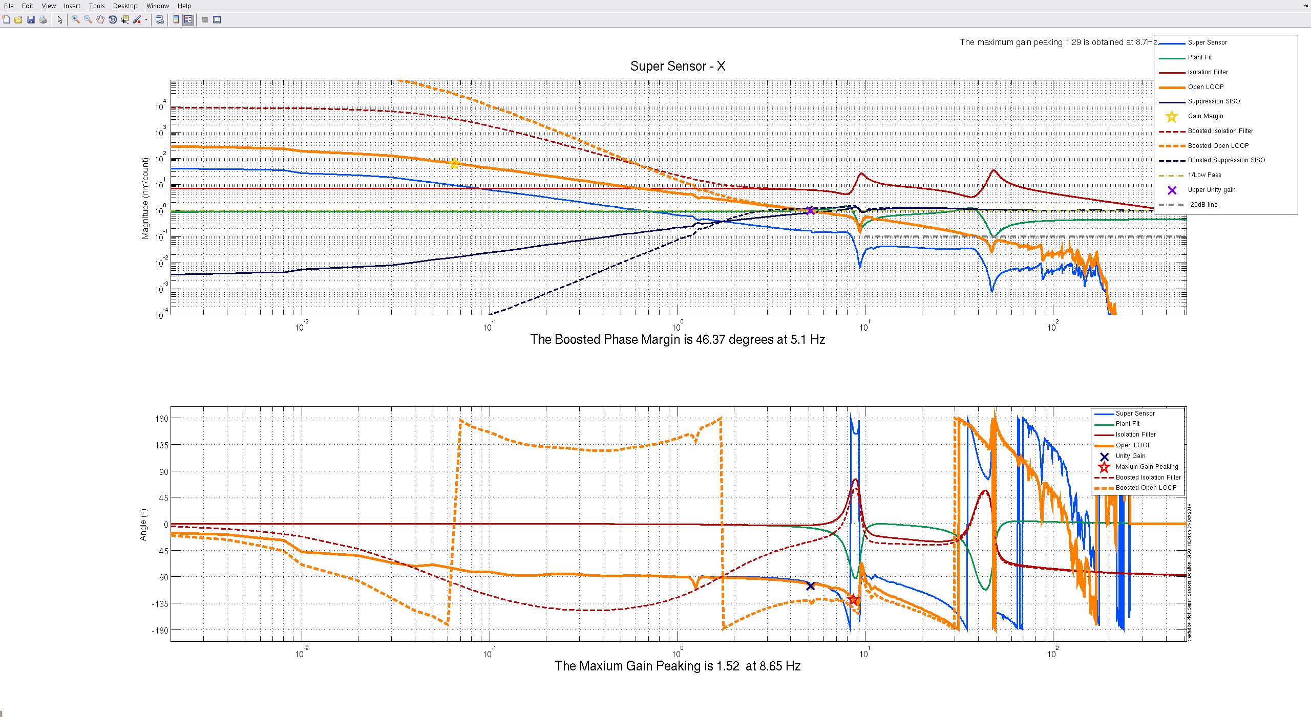
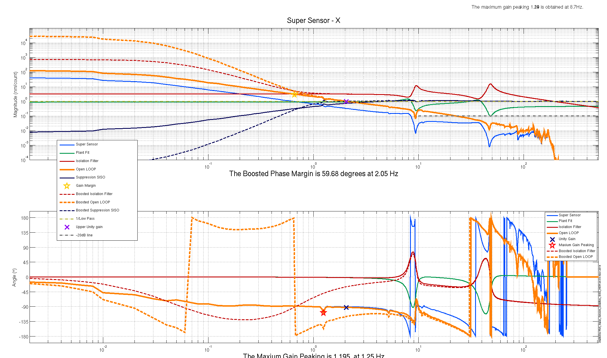
Attached are plots of dust counts > .5 microns in particles per cubic foot.
B. Bland, J. Bartlett, T. Sadecki, J. Kissel After noticing suspicious, what-appears-to-be, cross-coupling of Yaw (Y) modes (1.1 and 2.05 Hz) into the Transverse (T) driven transfer function of Garcia's a few days ago (see LHO aLOG 3769), Betsy and I plotted those results against other suspensions, just to confirm this is something unique to this suspension (remember, this guy has given us trouble after trouble already, see LHO aLOG 3714). The first attachment (allhstss_2012-08-13_X1SUSMC3_ALL_ZOOMED_TFs.pdf) shows this comparison between X1 SUS MC1 -- a phase 1b, metal mass, SUS; built by the same people, measured in the same place, in the same measurement phase. Doesn't show it (not thing common to this phase of an HSTSs life). L1 SUS MC2 -- a phase 3b, glass mass, SUS; built by different people, measured on an ISI in-chamber. Doesn't show it (not a location thing, not a glass mass vs. metal mass thing, not a "who assembled it thing). L1 SUS MC2 -- a phase 2b, glass mass, SUS; built originally by the same people, measured after glass swapping. Doesn't show it (not an "appears or goes away" through the phases thing). X1 SUS MC3 -- the latest measurement of concern, DAMPING LOOPS OFF. This shows the cross-coupling. X1 SUS MC3 -- the latest measurement of concern, DAMPING LOOPS ON. This does NOT show the cross-coupling. Given this comparison, we came up with three scenarios that we could image that would case Y to couple to T, and have any other cross coupling show up in other degrees of freedom. They're similar to what's shown for P to V coupling in G1100865 (pg 4): (1) The SD coil drive axis is mis-aligned with the SD magnet axis (though the axis are parallel to each other), creating a small lever arm causing the top mass to twist in Y when pushed in T (2) The SD magnet is cocked (in such a way that the whole flag-magnet assembly looks like a "z" shape), such that the SD coil driver axis non-parallel with the the SD magnet axis (but the flag is still aligned), creating a small Yaw force vector when driving in T (3) The TOP mass has its adjustment mass arranged very lop-sidedly (that's a word, right?), such that the T center of mass / Y moment of inertia is pushed forward or backward (i.e. in +/- L), which creates a small lever arm, twisting the mass, when forced along the mass center line, which is no longer in line with the CoM/MoI. As such, we recommended Bartlett to make a corresponding assessment of those features. He confirmed the mass distribution was in no way abnormal, so that rules out (3). He did readjust the the SD OSEM to center it a bit better. However, he only used the slop inherent to the BOSEM mounting; there really is no adjustment possible to the tablecloth -- its location is rigidly define by the cage -- so wasn't able to move it much. Not to mention, moving the tablecloth would affect the alignment of all other TOP OSEMs. After, he took a quick T to T (only) transfer function which is attached (and calibrated straight from DTT, woo!), 2012-08-13_1245_X1SUSMC3_M1_T-T_TF.pdf. It shows no improvement. That rules out option (1) (queue sad trombone). This doesn't rule out option (2) though... -------------------- Conclusions: - I'm not super concerned yet: - The cross-coupling goes away with damping loops closed (the normally-used configuration). - There are many more chances to attack this problem. - These two twins (MC1 and MC3) have been sitting in the staging building dragging there feet for a long time. SO -- given the absence of [further ideas/low-hanging solutions], Betsy and I've agreed that the best course forward is to just tackle this problem chamber-side, and let the assembly get on to more suspensions. I still would like to see spectra from this guy though, to show that his lower stage OSEMs are functional...
Main Crane and East Crane in the morning - Apollo Ham5 ISI Cabling - Corey and Jim W Work at HAM3 - Jeff B HWS Calibration at EY - Aidan Install optics in laser enclosure by HAM6- Alastair Extend purge air header - Kyle
From LLO, I have enabled the damping and launched the first TF measurement on PR2 (chamberside, with glass).
Mark Barton and Jeff Bartlett Further to the PR2 flag repair on Friday ( https://alog.ligo-wa.caltech.edu/aLOG/index.php?callRep=3813 ), we went in this morning and retracted and removed the repair jig. The magnet-standoff assembly stayed in place and looked good, so we set all OSEMs to half-light ready for testing.
Before inserting the HAM5-ISI, we took an inventory of SEI In-Vac Cabling. Below we list the Part # (D1000***) & Serial Number as:
-Part# / -s/n
Corner 1
Corner 2
Corner 3
Summary: magnetic field injections suggest that the coupling to test mass motion is at least 3 orders of magnitude too high.
We measured magnetic coupling by injecting known magnetic fields with two coils set up in pseudo-Helmholtz configuration on opposite sides of ITMY (Figure 1). We measured the resulting test mass motion using the calibrated one arm test length channel and the ITMY optical lever channels. The optical lever calibrations were run past Jeff K. to make sure we had the right ones. The magnetometer was placed right under the floor of BSC8, within a meter of the test mass, and was calibrated in-situ using a calibration coil. To estimate the motion produced by ambient fields, the motion we observed was reduced by the ratio of our injected fields to ambient magnetic fields measured during S6 science mode (about 20 pT/sqrt(Hz) between 2 and 15 Hz, a few nanotesla at 60 Hz).
Figure 2 is an example of our injections, showing the signal produced by a 63 Hz magnetic injection on the magnetometer and the ITMY yaw channels. Figure 3 is a summary of the predicted motion from ambient fields. The point at 63 Hz is calculated using the ambient 60 Hz background instead of the 63 Hz background so that it serves as an estimate of the 60 Hz peak in the gravitational wave channel produced by the ambient 60 Hz field. The predicted motion at 11.5 Hz is about 1e-16 m or radians/sqrt(Hz), and at 60 Hz is almost 1e-14. These values are at least 3 orders of magnitude higher then desired.
Our preliminary guess is that the excess coupling is to HEPI or the ISI because motion sensors on the HEPI and ISI suggest that our injections cause HEPI and ISI motions that are orders of magnitude over background (Figure 4). Arguing against this is the observation that predicted motion only goes as roughly 1/f^3 (see Figure 3); if the coupling were only to HEPI and ISI, we would expect that the 4 passive pendulums would result in a greater frequency dependence. Our first planned step in trying to sort this out is to compare coupling with HEPI and ISI turned off.
We investigated the possibility that the magnetic fields were coupling at HEPI and ISI cable feedthroughs using a small coil. We saw a variation in coupling for different feedthroughs, but we have not reached definite conclusions.
Robert Schofield, Maggie Tse
I locked the arm cavity for about half an hour but the lock broke when I enabled the isolation on ITMY ISI and the HEPI and ISI watchdogs tripped. After that I couldn't' restore the watchdogs anymore. The arm is currently unlocked.
The ALS reference cavity was in an unstable mode and the PLL could not get locked. I re-locked the refcav with these settings: Coarse 384 Fine 206 Common 300 Fast 638 Offset 194 The fiber output has dropped from ~300 uW to 80 uW since Bram installed a Faraday at the output of the reference cavity. As a consequence the beat note amplitude is about -25 dBm (-35 dBm at the monitor spigot of the phase/freq discriminator board). I had to increase the laser power otherwise the amplitude would have been even smaller. The PLL is now locked again, with the laser at the end station set to 42.27 degrees. Locking the PLL was tricky. One of the switches in the CMB_A MEDM screen was actually stuck in an open state, although it appeared to be closed on the screen. the switch was malfunction and it had a state value of 65536 instead of 1 or 0. I forced it to be 1 by EZCAWRITE. Also there CMB_A board Input1 gain is now limited to -16 or less, vs -6 as it used to be, because the PLL becomes unstable at -15 and up. This is strange since the loop gain phase is flat up to 80 kHz and the phase margin is large (~60 degrees up to 80 kHz; the UGF is 10 kHz). I suspect something might be wrong with the slow control interface of CMB_A.
I reset all the watch dogs on the ITM HPI and ISI. ITM ISI is in damping state. Didn't press the isolate stage command.
I try to lock the arm (remotely), but it seems that H2:ALS-Y_FIBR_SERVO_FASTMON (e.g. the CMB-A fast output, which is the fiber locking feedback signal to the laser PZT) is railed at -10V. The beatnote frequency readout is at 60 MHz, but not sure if that is real or not. Should go out to EY to make sure all is well. (PS. to engage the fiber locking open the 'Laser' screen and press 'on' at the lower left).
I turned off the FIBR servo (CMB-A), to make sure the temperature doesn't walk away.
The OAT RefCav monitor signal seems to be ok (~0.1 mW).
Turned off ETMy ring heater
[David T, Cheryl V and Deepak K]
[David T, Cheryl V and Deepak K]
The backup of h1boot and h2boot still slows the EPICS associated with the front end systems. Even though I only backup at 5am daily, the slow down is still evident at that time. Until the root cause of this problem can be resolved, Jim and I came up with a totally inelegant solution of slowing down the data rate of the network switch ports which connect h1boot and h2boot to the backup machine. These ports were demoted from 1GB to 100MB. We tested both h1boot and h2boot backups. They take about an hour each (compared with 20mins previously). The disk I/O rate keeps below 5MB per 5 second average. The EPICS problems were previously observed to occur when the disk I/O exceeds 8MB per 5 second average.
A large percentage of the backups concern the awgtpman log files which can be many 100MB each. We will work next Tues on installing new awgtpman code to reduce the logging content of these files.
The arm cavity is unlocked right now due to issues with the HEPI on ITMY.
I have installed the IOP SUS watchdog system for the H1 HAM2,3 systems. The sus systems are h1sush2a and h1sush34, the seismic system is h1seih23. Following the LLO system, the suspension systems being monitored are
HAM2: PR3
HAM3: PR2 and MC2
If any of these sus system trip, the DACs on h1seih23 (HEPI and ISI in HAMS 2,3) are tripped via the Dolphin IPC.
Currently SEI HAM2,3 is permanently tripped due to missing PR3 OSEMS. I will reconfigure the system into a working state when the ISI are unlocked in HAM2/3.
The H1 IOP watchdog MEDM is available from the H1 SITEMAP
I turned on the ETMY ring heater around 23:47 UTC, requesting 630mA in each segment. I'm going to leave it running overnight and into the weekend to get a good measurement of the thermal time constants.
After finishing assessing and adjusting the roll and pitch of the suspensed PR2 optic, we started adjusting the 14 OSEM positions. During the coarse of this, we broke a magnet off of the PR2 optic. Mark Barton and Travis are looking into regluing it onto the optic within the suspension, in an effort to retain some sort of schedule for next week while our team is stretched over to LLO. Lesson learned is that the EQ stops need to be set very close while adjustments are being made. I thought this was the case when we were working on it, but clearly not close enough. It's unfortunate that the top BOSEM adjustment tools and your hand are very close to the suspension wire making knocking the suspended masses around easy.
Mark Barton and Travis Sadecki We did a repair as follows: 1. We set up a jig using parts from the AOSEM tester, including two translation stages, some posts, and a holder intended for a 10x10 magnet (see attached photo). 2. We cleaned up the magnet-standoff assembly and adhered it magnetically to the steel disk of the magnet holder. 3. We aligned the new standoff with the glue ring on the optic from the original standoff using the translation stages. 4. We backed off the standoff and removed the glue ring with a razor blade and an acetone swab. 5. We applied glue to the standoff and brought it in to touch the optic. The glue will be left to set over the weekend and then the magnet holder should be able to be backed away - the magnetic attraction is not very strong.
Mitchell, Jim & Hugh The first layer of the additional payload mass (D0901075) on the West side of HAM (90kg) has been bolted down to the table; we did this Thursday. There is still 210kg to go.