david.barker@LIGO.ORG - posted 10:27, Sunday 09 March 2025 (83250)
Sun CP1 Fill
Sun Mar 09 10:08:50 2025 INFO: Fill completed in 8min 47secs
Images attached to this report
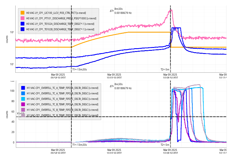
Sun Mar 09 10:08:50 2025 INFO: Fill completed in 8min 47secs
Over roughly 7hrs, we had 2-consecutive ETMx Glitch locklosses taking H1 down from OBSERVING.
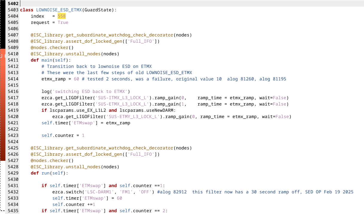
After that last lockloss, have had 2-consecutive LOWNOISE_ESD_ETMX locklossess while trying to get H1 back. An alog search on LOWNOISE_ESD_ETMX lockloss issues were noted in alog82912. Since we are having a similar situation (high microseism and frequent locklosses at this state), I made changes to LOWNOISE_ESD_ETMX in ISC_LOCK.py by increasing the (1) ETMx ramp time & (2) a timer after this step (see attached):
Change Save & Loaded for ISC_LOCK and we are currently on the way to see if we can get through LOWNOISE_ESD_ETMX (or have a 3rd Consecutive lockloss here).
Well, that didn't work. H1 had a 3rd-consecutive lockloss within a couple seconds of going through LOWNOISE_ESD_ETMX. (Posted situation on mattermost & consulting the Call List for assistance.)
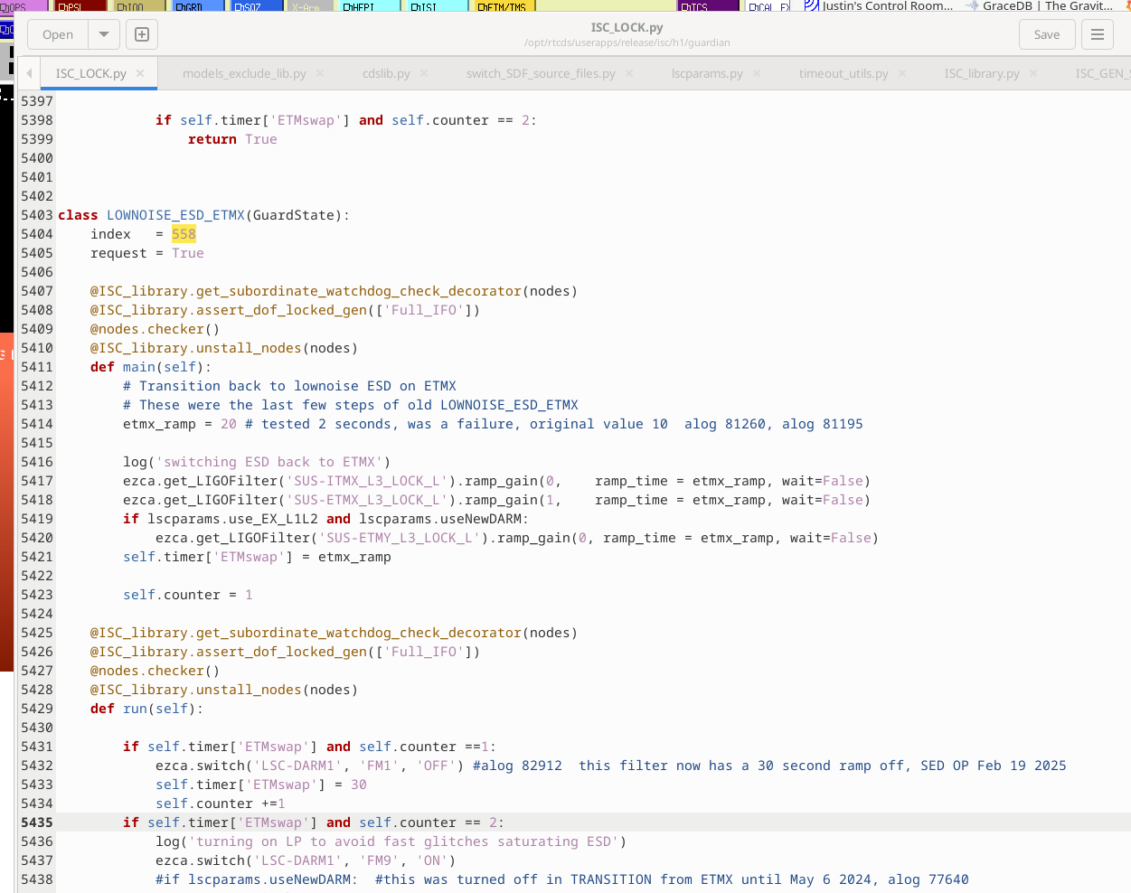
So, I am restoring the (1) etmx_ramp back to 20 (from my 60) & (2) self.timer['ETMswap'] back to 30 (from 60).
Attached is the restored values noted above.
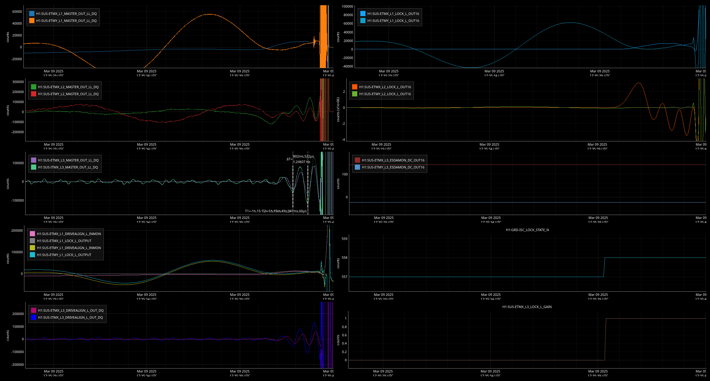
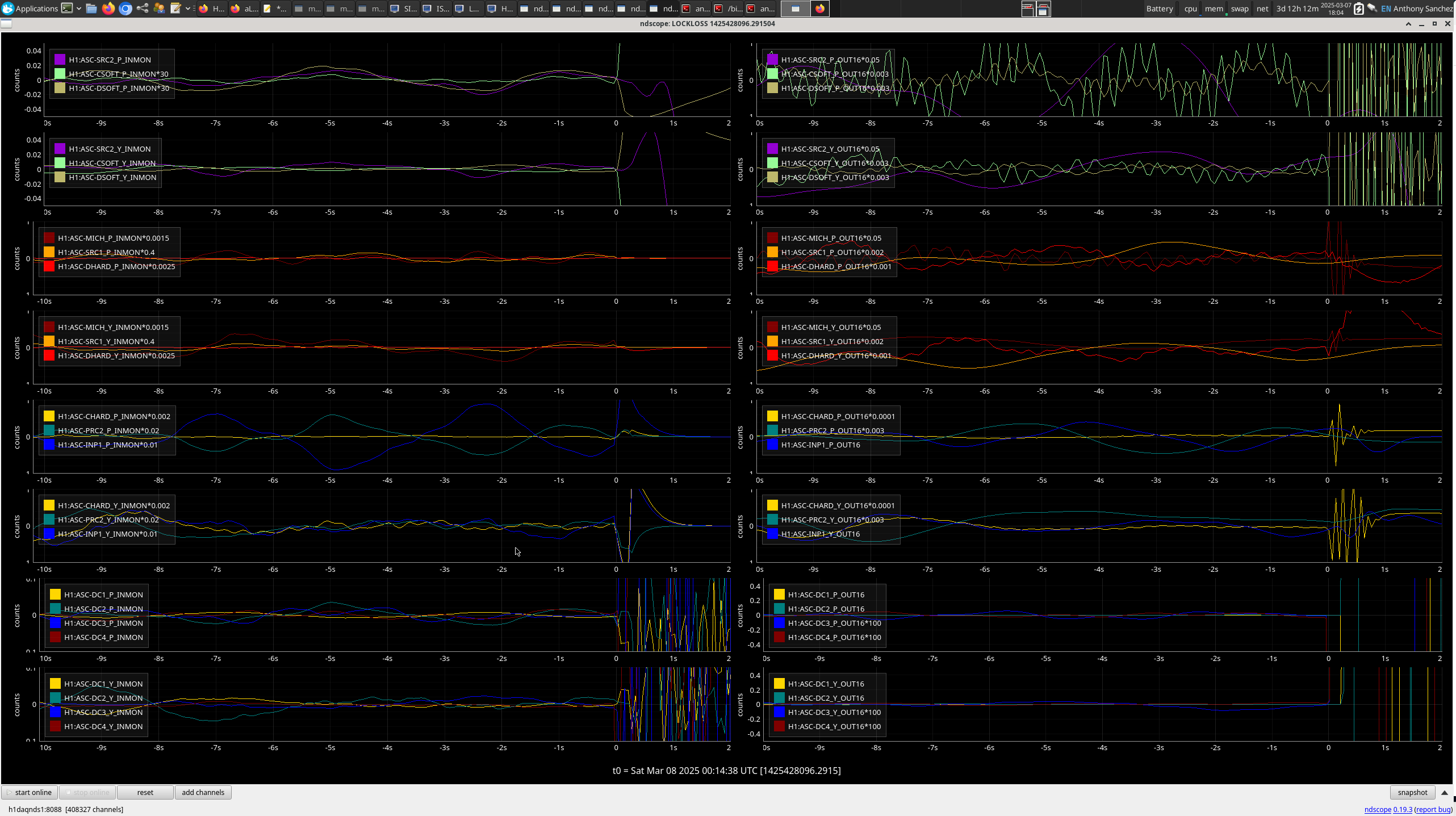
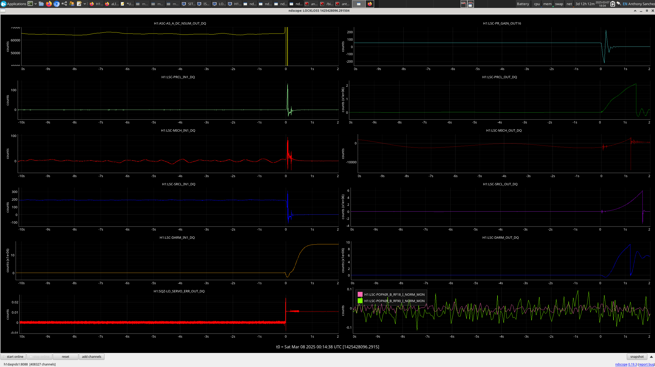
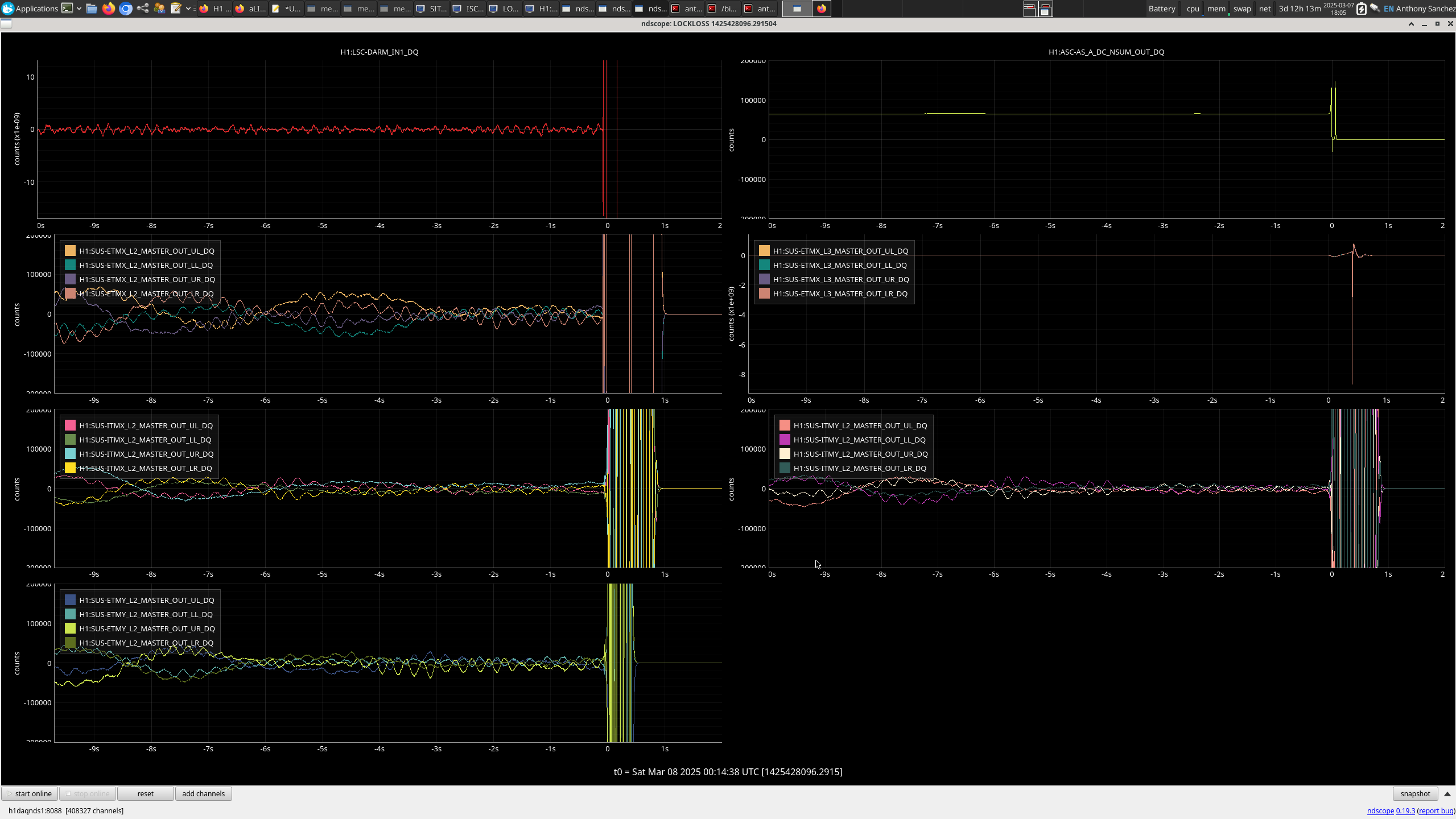
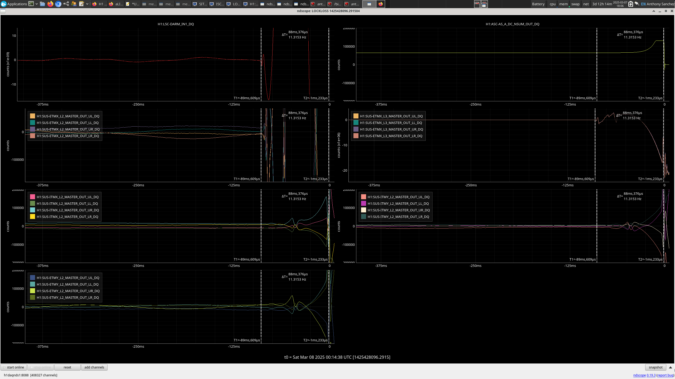
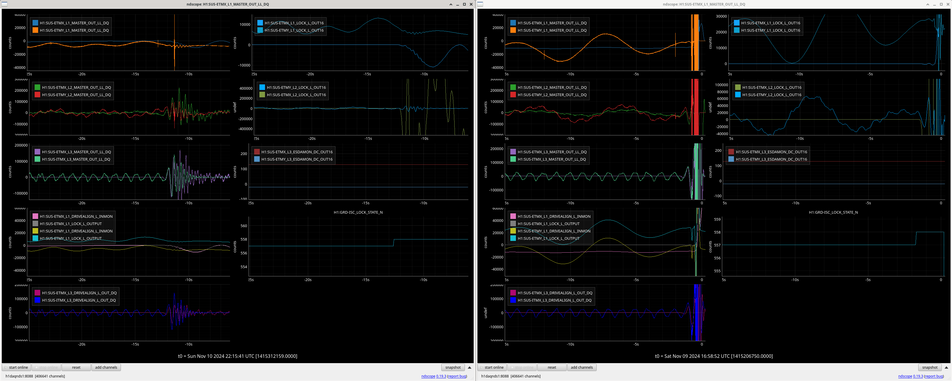
Below you can see what happened---lockloss happened FAST within 4-seconds of starting LOWNOISE_ESD_ETMx. Jim wsa first on the call list and he asked if his ETMx ESD limit steps happen---they did not even get to try---that step is the LAST step for LOWNOISE_ESD_ETMx.
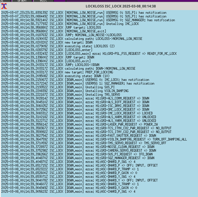
Here is the ISC_LOCK for this lockloss:
2025-03-09_17:35:40.042953Z ISC_LOCK [TRANSITION_FROM_ETMX.run] timer['ETMswap'] done
2025-03-09_17:35:40.092335Z ISC_LOCK [TRANSITION_FROM_ETMX.run] ADS convergence check
2025-03-09_17:35:40.195243Z ISC_LOCK EDGE: TRANSITION_FROM_ETMX->LOWNOISE_ESD_ETMX
2025-03-09_17:35:40.195907Z ISC_LOCK calculating path: LOWNOISE_ESD_ETMX->NOMINAL_LOW_NOISE
2025-03-09_17:35:40.196027Z ISC_LOCK new target: LOWNOISE_LENGTH_CONTROL
2025-03-09_17:35:40.201276Z ISC_LOCK executing state: LOWNOISE_ESD_ETMX (558)
2025-03-09_17:35:40.206296Z ISC_LOCK [LOWNOISE_ESD_ETMX.enter]
2025-03-09_17:35:40.216682Z ISC_LOCK [LOWNOISE_ESD_ETMX.main] switching ESD back to ETMX
2025-03-09_17:35:40.217217Z ISC_LOCK [LOWNOISE_ESD_ETMX.main] ezca: H1:SUS-ITMX_L3_LOCK_L_TRAMP => 60
2025-03-09_17:35:40.217751Z ISC_LOCK [LOWNOISE_ESD_ETMX.main] ezca: H1:SUS-ITMX_L3_LOCK_L_GAIN => 0
2025-03-09_17:35:40.218187Z ISC_LOCK [LOWNOISE_ESD_ETMX.main] ezca: H1:SUS-ETMX_L3_LOCK_L_TRAMP => 60
2025-03-09_17:35:40.218678Z ISC_LOCK [LOWNOISE_ESD_ETMX.main] ezca: H1:SUS-ETMX_L3_LOCK_L_GAIN => 1
2025-03-09_17:35:40.219270Z ISC_LOCK [LOWNOISE_ESD_ETMX.main] ezca: H1:SUS-ETMY_L3_LOCK_L_TRAMP => 60
2025-03-09_17:35:40.219711Z ISC_LOCK [LOWNOISE_ESD_ETMX.main] ezca: H1:SUS-ETMY_L3_LOCK_L_GAIN => 0
2025-03-09_17:35:40.219923Z ISC_LOCK [LOWNOISE_ESD_ETMX.main] timer['ETMswap'] = 60
2025-03-09_17:35:44.717933Z ISC_LOCK [LOWNOISE_ESD_ETMX.run] Unstalling IMC_LOCK
2025-03-09_17:35:44.853115Z ISC_LOCK [LOWNOISE_ESD_ETMX.run] USERMSG 0: IMC_LOCK: has notification
2025-03-09_17:35:45.067039Z ISC_LOCK JUMP target: LOCKLOSS
2025-03-09_17:35:45.070405Z ISC_LOCK [LOWNOISE_ESD_ETMX.exit]
2025-03-09_17:35:45.140996Z ISC_LOCK JUMP: LOWNOISE_ESD_ETMX->LOCKLOSS
2025-03-09_17:35:45.141251Z ISC_LOCK calculating path: LOCKLOSS->NOMINAL_LOW_NOISE
2025-03-09_17:35:45.142460Z ISC_LOCK new target: DOWN
2025-03-09_17:35:45.150074Z ISC_LOCK executing state: LOCKLOSS (2)
2025-03-09_17:35:45.150466Z ISC_LOCK [LOCKLOSS.enter]
2025-03-09_17:35:45.154072Z ISC_LOCK [LOCKLOSS.main] ezca: H1:GRD-PSL_FSS_REQUEST => READY_FOR_MC_LOCK
2025-03-09_17:35:45.267242Z ISC_LOCK JUMP target: DOWN
2025-03-09_17:35:45.271745Z ISC_LOCK [LOCKLOSS.exit]
2025-03-09_17:35:45.331052Z ISC_LOCK JUMP: LOCKLOSS->DOWN
2025-03-09_17:35:45.331185Z ISC_LOCK calculating path: DOWN->NOMINAL_LOW_NOISE
None of the first 3 LOWNOISE_ESD_ETMx (558) locklosses have an IMC tag. (3rd one had a WINDY tag & we did transition back to SEI_ENV = USEISM at 1721utc (about an hr ago).)
All 3 have the REFINED tag.
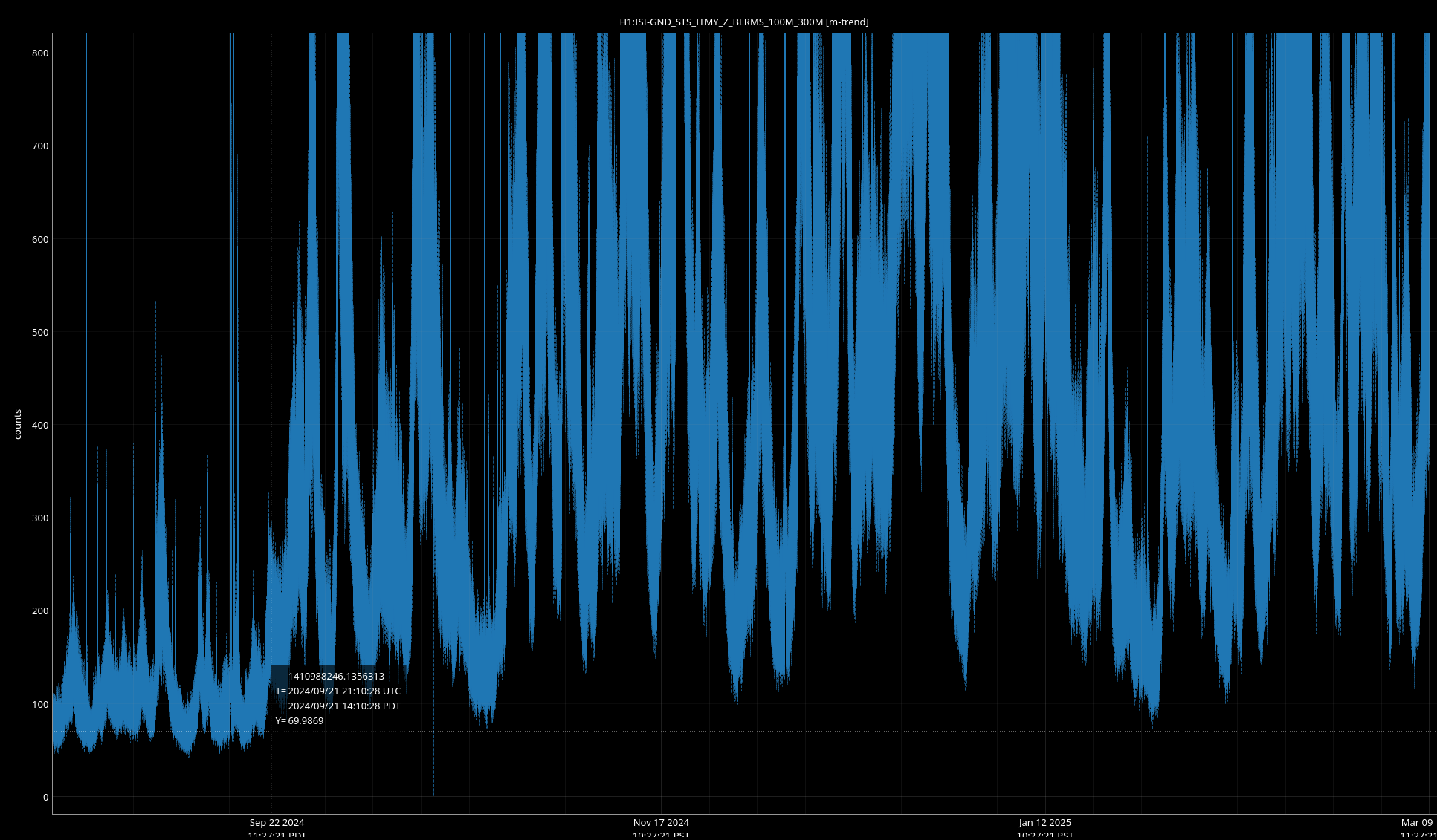
A Look At Microseism with comparson to Elenna's plot in Nov when the microseism season was starting and here we are a few more months into it. We've certainly had worse days, but we are in the middle of a noisy microseism period at about 600 counts since last night.
STATUS: Have been holding at MAX_POWER [520]
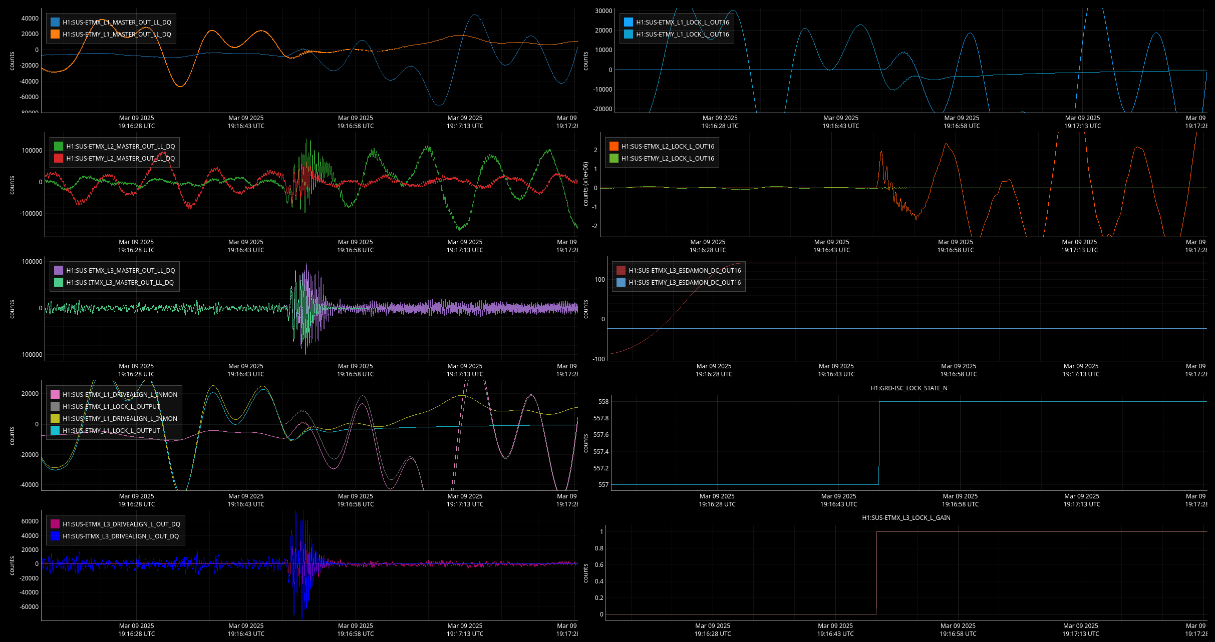
Here is a look at the last LOWNOISE_ESD_ETMx (using an Elenna template).
For the 4th locking attempt, time settings were restored (from change I made), and on this one I held at MAX POWER [520] for about 50min while reading through alogs, looking at previous lockloss to post in the alog and then eventually just continued on, and this time, H1 made it thru LOWNOISE_ESD_ETMx. Attached you can see how things looked going from TRANSITION FROM ETMX [557] to LOWNOISE ESD ETMX [558]....in contrast to my lockloss alogged earlier, this one looks like sort of like the plot on left from Elenna's scopes posted here.
TITLE: 03/09 Day Shift: 1430-2330 UTC (0730-1630 PST), all times posted in UTC
STATE of H1: Lock Acquisition
OUTGOING OPERATOR: Ryan S
CURRENT ENVIRONMENT:
SEI_ENV state: USEISM
Wind: 10mph Gusts, 6mph 3min avg
Primary useism: 0.04 μm/s
Secondary useism: 0.45 μm/s
QUICK SUMMARY:
Happy Spring Forward Morning (& 1-hr less sleep)!
H1 just went down (after a 3h51m lock, and a 1435utc lockloss w/ an ETMx Glitch tag). Taking H1 immediately into Initial Alignment to skip Locking ALS locklosses.
The one Owl 932utc lockloss (also an ETMx Glitch tag) was fully automatic (after about 22min of 7 Locking ALS attempts) & no Alignment was needed.
Looks like secondary microseism hit the 95th percentile about 10hrs ago and has stayed there. Winds are under 10mph.
TITLE: 03/09 Eve Shift: 0030-0600 UTC (1630-2200 PST), all times posted in UTC
STATE of H1: Observing at 145Mpc
INCOMING OPERATOR: Ryan S
SHIFT SUMMARY:
IFO is in NLN and OBSERVING as of 01:36 UTC (~4hr 30 min lock).
Extremeley calm IFO that stayed locked for majority of shift.
Lock acquisition after the EQ lockloss (alog bla bla) went fully automatically.
Since then, we've been locked with the microseism steadily increasing. However, the wind has died down.
PSL Dust has been fluctuating a lot (swapping between red, yellow and no alerts) this shift, despite wind calming down.
LOG:
None
TITLE: 03/08 Day Shift: 1530-0030 UTC (0730-1630 PST), all times posted in UTC
STATE of H1: Lock Acquisition
INCOMING OPERATOR: Ibrahim
SHIFT SUMMARY:
Two locklosses today which were straightforward to recover from. One happened at the waning minutes of the calibration suite of measurements which is sad (EQ inbound, higher winds, and microseism increasing); this was tagged as a WIND + Calibration lockloss.
Also had 5-tours for our 2nd Saturday Tour day.
LOG:
Lockloss due to EQ, exacerbated by a 5.9 EQ (which interestingly didn't trigger EQ mode).
IFO is relocking now.
TITLE: 03/09 Eve Shift: 0030-0600 UTC (1630-2200 PST), all times posted in UTC
STATE of H1: Observing at 149Mpc
OUTGOING OPERATOR: Corey
CURRENT ENVIRONMENT:
SEI_ENV state: SEISMON_ALERT
Wind: 26mph Gusts, 21mph 3min avg
Primary useism: 0.07 μm/s
Secondary useism: 0.41 μm/s
QUICK SUMMARY:
IFO is in NLN and OBSERVING as of 21:22 UTC (3 hr lock).
Unfortunately, we have a 5.9 EQ arriving in a few minutes. If microseism was lower, we could probably ride it out but seeing as we lost lock due to a lower mag EQ with lower microseism just 4ish hrs ago, I would say chances are low.
Calibration sweep did not run today due to an EQ so I can run one pending thermalization (and green light from comissioners/run coord).
Sat Mar 08 10:08:10 2025 INFO: Fill completed in 8min 7secs
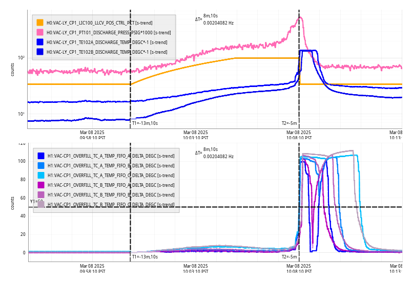
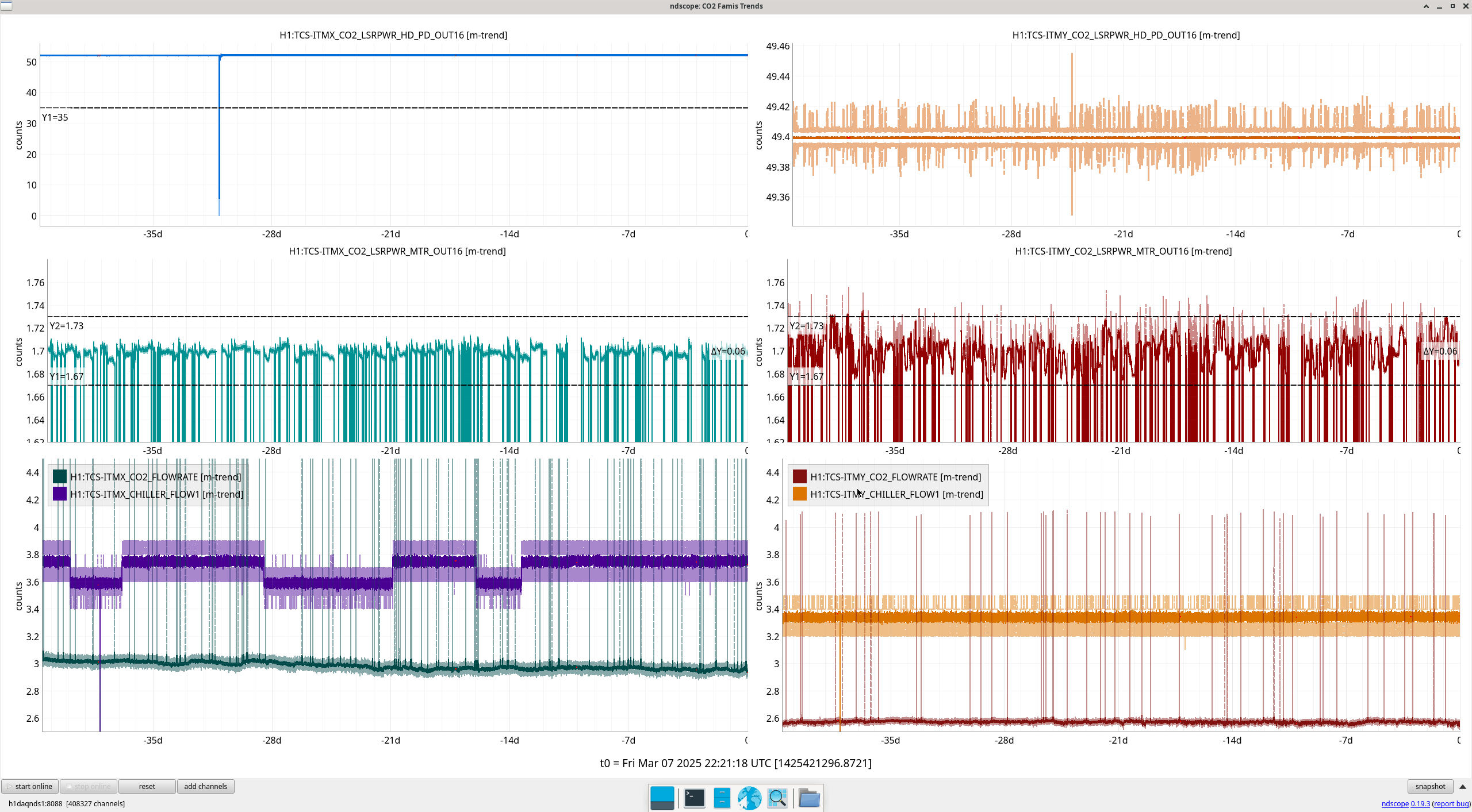
FAMIS Link: 26033
Only CPS channels which look higher at high frequencies (see attached) would be the following:
TITLE: 03/08 Day Shift: 1530-0030 UTC (0730-1630 PST), all times posted in UTC
STATE of H1: Lock Acquisition
OUTGOING OPERATOR: Ryan S
CURRENT ENVIRONMENT:
SEI_ENV state: CALM
Wind: 8mph Gusts, 3mph 3min avg
Primary useism: 0.03 μm/s
Secondary useism: 0.31 μm/s
QUICK SUMMARY:
H1 had a lockloss about 70min ago due to an ETMx Glitch, due to trouble locking ALS, automation finished up an alignment 10min ago and continues locking (H1 had a pretty quick automated acquisitioon overnight in about 90min for comparison). Secondary microseism has a slow increase over the last 12-ish hours and it has been a little breezy the last 24hrs (w/ gusts going over 20mph at various points). Today is Saturday Tour day & Calibration is scheduled for 1830utc/1130amPST.
TITLE: 03/08 Eve Shift: 0030-0600 UTC (1630-2200 PST), all times posted in UTC
STATE of H1: Observing at 149Mpc
INCOMING OPERATOR: Ryan S
CURRENT ENVIRONMENT:
SEI_ENV state: SEISMON_ALERT
Wind: 9mph Gusts, 6mph 3min avg
Primary useism: 0.02 μm/s
Secondary useism: 0.26 μm/s
SHIFT SUMMARY:
Had a lockloss just before my shift.
Did some SQZr changes while relocking : Corey's alog: 83225 , My alog about this: 83236
Once Relocked H1 has stayed locked and Observing for 3 hours.
LOG:
| Start Time | System | Name | Location | Lazer_Haz | Task | Time End |
|---|---|---|---|---|---|---|
| 18:34 | isc | myank.siva | optics.lab | y | iss array hardware | 01:50 |
| 01:26 | ISS | Matt | Optics Lab | Yes | Taking pics of Fiber Lasers | 01:32 |
TITLE: 03/08 Eve Shift: 0030-0600 UTC (1630-2200 PST), all times posted in UTC
STATE of H1: Aligning
OUTGOING OPERATOR: Corey
CURRENT ENVIRONMENT:
SEI_ENV state: CALM
Wind: 15mph Gusts, 11mph 3min avg
Primary useism: 0.02 μm/s
Secondary useism: 0.21 μm/s
QUICK SUMMARY:
00:14 UTC H1 Aquired a Lockloss of unknown cause.
There was a request to load the SQZ_SHG Guardian, but there was a syntax in the code that caused the Guardian node to go into error. Simple fix took me a few minute to find and fix.
SQZ_SHG Guardian node is running smoothly now.
Corey then took H1 into Initial_Alignment, while I edited the sqzparams.py.
Line 18 was take from 75 to 80:
opo_grTrans_setpoint_uW = 80 #reload OPO guardian for this to take effect
I then took SQZ_OPO_LR Guardian to LOCKED CLF_DUAL_NO_ISS, Then reloaded the Guardian code.
Once reloaded I took SQZ_OPO_LR back to LOCKED_CLF_DUAL.
Then tried to adjust the OPO_TEC_TEMP, this was a mistake. I could tell that something wasnt correct because I couldn't get the SQZ-CLF_RFEL_RF6_ABS_OUTPUT back to the same hieght it was before while adjusting the OPO_TEC_TEMP. Contacted Sheila.
She informed me that the SQZ_CLF_LR should be locked when doing this.
Once locked the SQZ-CLF_RFEL_RF6_ABS_OUTPUT went up and Looked much better.
Relocking notes.
Initial_Alignment is finished and I'm trying to relock and I have not had success past DRMI. But the night is stil young.
Update:
NOMINAL_LOW_NOISE reached at 2:50 UTC
Observing reached at 3:02 UTC
TITLE: 03/07 Day Shift: 1530-0030 UTC (0730-1630 PST), all times posted in UTC
STATE of H1: Observing at 149Mpc
INCOMING OPERATOR: Tony
SHIFT SUMMARY:
edit: h1 had a lockloss minutes before the end of the shift, so Tony and I started addressing SQZ To-Dos (see below in the log)
Ops To Do At Next Opportunity (next H1 lockloss, or L1 goes down. See sheila alog 83227):
LOG:
def in_hardfault():
#if ezca['SQZ-LASER_IR_DC_ERROR_FLAG'] != 0:
# notify('Squeezer laser PD error')
# return True
#elif ezca['SQZ-PMC_TRANS_DC_ERROR_FLAG'] != 0:
# notify('Squeezer PMC not locked')
# return True
if ezca['SQZ-SHG_TRANS_RF24_PHASE_ERROR_FLAG'] != 0:
notify('SHG Trans phase shifter error')
return True
#elif ezca['SQZ-SHG_TRANS_RF24_DEMOD_ERROR_FLAG'] != 0:
# notify('SHG Trans Demod error')
# see comment to alog 83224 for why this was commented out
# return True
J. Kissel

I've been looking through the data captured about the PMC in the context of the two years of observatory use between July 2022 and July 2024 where we spanned a few "construction, commission, observe" cycles -- see LHO:83020. Remember the end goal is to answer the following question as quantitatively as possible: "does the PMC have a high enough duty cycle in the construction and commissioning phases that the SPI does *not* need to buy an independent laser?"

Conclusions:
 - Since the marked change in duty cycle after the PMC lock-loss event on 2023-05-16, the duty-cycle of the PMC has been exceptionally high, either 91% during install/commissioning times or 99% during observing times.
 - Most of the down time is from infrequent planned maintenance.
 - Recovery time is *very* quick, unless the site loses power or hardware fails.
 - The PMC does NOT lose lock when the IFO loses lock.
 - The PMC does NOT lose lock just because we're vented and/or the IMC is unlocked.
 - To-date, there are no plans to make any major changes to the PSL during the first one or two O4 to O5 breaks.
So, we shouldn't expect to lose the SPI seed light frequently, or even really at all, during the SPI install or during commissioning. And especially not during observing.

This argues that we should NOT need an independent laser from an "will there even be light?" "won't IFO construction / commissioning mean that we'll be losing light all the time?"  duty-cycle stand point.
Only the pathfinder itself, when fully functional with the IFO, will tell us whether we need the independent laser from a "consistent noise performance" stand-point.

Data and Historical Review
To refresh your memory, the major milestones that happened between 2022 and 2024 (derived from a two year look through all aLOGs with the H1 PSL task):
- By Mar 2022, the PSL team had completed the complete table revamp to install the 2x NeoLase high-power amps, and addressed all the down-stream adaptations.

- 2022-07-01 (Fri): The data set study starts.
- 2022-09-06 (Tue): IO/ISC EOM mount updated, LHO:64882
- 2022-11-08 (Tue): Full IFO Commissioning Resumes after Sep 2022 to Dec 2022 vent to make FDS Filter Cavity Functional (see E2000005, "A+ FC By Week" tab)
- 2023-03-02 (Thu): NPRO fails, LHO:67721
- 2023-03-06 (Mon): NPRO and PSL function recovered LHO:67790
- 2023-04-11 (Tue): PSL Beckhoff Updates LHO:68586
- 2023-05-02 (Tue): ISS AOM realignment LHO:69259
- 2023-05-04 (Thu): ISS Second Loop Guardian fix LHO:69334
- 2023-05-09 (Tue): "Something weird happened to the PMC, then it fixed itself" LHO:69447
- 2023-05-16 (Tue): Marked change in PSL PMC duty-cycle, nothing specific PSL team did with the PMC, but the DC power supplies for the RF & ISC racks we replaced, 69631, while Jason tuned up the FSS path LHO:69637
- 2023-05-24 : O4, and what we'll later call O4A, starts, we run with 75W requested power from the PSL.
- 2023-06-02 (Fri): PSL ISS AA chassis it was replaced, but PMC stays locked through it LHO:70089
- 2023-06-12 (Sun): PMC PDH Locking PD needs threshold adjustment, LHO:70352, for "never found out why" reason FRS:28260
- 2023-06-19 (Mon): PMC PDH Locking PD needs another threshold adjustment, LHO:70586, added to FRS:28260, but again reasons never found.
- 2023-06-21 (Wed): Decision made to reduce requested power into the IFO to 60W LHO:70648
- 2023-07-12 (Wed): Laser Interlock System maintenance kills PSL LHO:71273
- 2023-07-18 (Tue): Routine PMC / FSS tuneup, with quick PMC recovery LHO:71474
- 2023-08-06 (Sun): Site-wide power glitch takes down PSL LHO:72000
- 2023-09-22 (Fri): Site-wide power gltich takes down PSL LHO:73045
- 2023-10-17 (Tue): Routine PMC / FSS tuneup, with quick PMC recovery LHO:73513
- 2023-10-31 (Tue): Jeff does a mode scan sweeping the PMC FSR LHO:73905
- 2023-11-21 (Tue): Routine PMC / FSS tuneup, with quick PMC recovery LHO:74346
- 2024-01-16 : O4A stops, 3 months, focused on HAM567, no PSL work (see E2000005, "Mid-O4 Break 1" tab)
O4A to O4B break lock losses: 7
       2024-01-17 (Wed): Mid-vent, no IFO, no reported cause.
       2024-01-20 (Sat): Mid-vent, no IFO, no reported cause.
       2024-02-02 (Fri): Mid-vent, no IFO, no reported cause.
       2024-02-08 (Thu): Mid-vent, no IFO, no reported cause. During HAM6 close out, may be related to alarm system
       2024-02-27 (Tue): PSL FSS and PMC On-table Alignment LHO:76002.
       2024-02-29 (Thu): PSL Rotation Stage Calibration LHO:76046.
       2024-04-02 (Tue): PSL Beckhoff Upgrade LHO:76879.
- 2024-04-10 : O4 resumes as O4B start
O4B to 2024-07-01 lock losses: 1
       2024-05-28 (Tue): PSL PMC REFL tune-up LHO:78093.
- 2024-07-01 (Mon): The data set study ends.

- 2024-07-02 (Tue): The PMC was swapped just *after* this data set, LHO:78813, LHO:78814

By the numbers

Duty Cycle (uptime in days / total time in days)
     start_to_O4Astart: 0.8053
    O4Astart_to_O4Aend: 0.9450
    O4Aend_to_O4Bstart: 0.9181
       O4Bstart_to_end: 0.9954
(Uptime in days is the sum on the values of H1:PSL-PMC_RELOCK_DAY just before lock losses [boxed in red] in the attached trend for the given time period)

Lock Losses (number of times "days" goes to zero)
     start_to_O4Astart: 80
    O4Astart_to_O4Aend: 22
    O4Aend_to_O4Bstart: 7
       O4Bstart_to_end: 1
(Number of lock losses is mere the count of red boxes for the given time period)

Lock Losses per calendar days
     start_to_O4Astart: 0.2442
    O4Astart_to_O4Aend: 0.0928
    O4Aend_to_O4Bstart: 0.0824
       O4Bstart_to_end: 0.0123
(In an effort to normalize the locklosses over the duration of the time period to give a more fair assessment.)

I also attach a histogram of lock durations for each duration, as another way to look at how the duty cycle dramatically changed around the start of O4A.
The data used in the above aLOG was gathered by ndscope using the following template,
    /ligo/svncommon/SeiSVN/seismic/Common/SPI/Results/
        alssqzpowr_July2022toJul2024_trend.yaml


and then exported (by ndscope) to the following .mat file,
    /ligo/svncommon/SeiSVN/seismic/Common/SPI/Results/
        alssqzpowr_July2022toJul2024_trend.mat


and then processed with the following script to produce these plots
    /ligo/svncommon/SeiSVN/seismic/Common/SPI/Scripts/
        plotpmcuptime_20250224.m    rev 9866


ndscope have become quite an epically powerful data gathering tool!
Closes FAMIS 28458. Last checked in alog 82659.
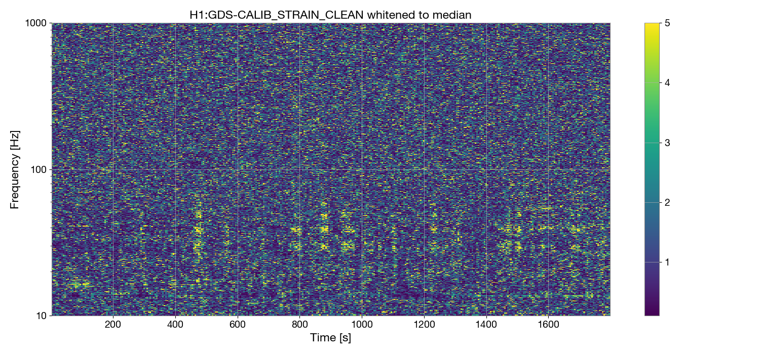
I found evidence of possible scattered light while looking at some data from a lock yesterday. Attached is a whitened spectrogram of 30 minutes of data starting at GPS 1425273749. It looks like the peaks are around 28, 38, and 48 Hz, but they are broad and it's hard to tell the exact frequency and spacing. Sheila thinks this may have appeared after Tuesday maintenance. Tagging detchar request so some tests can be run to help us track down the source!
Ryan Short and I have been looking through the summary pages to see what we could learn about this.
Our range has been shaggy and low since Tuesday, this does seem to line up well with Tuesday maintence. Comparing the glitch rate before and after Tuesday isn't as easy, Iara Ota pointed me to the DMT omega glitch pages to make the comparison for Wed when omicron wasn't working. DMT omega pages don't show the problem very clearly, but the omicron based ones do show more glitches SNR 8 and higher since Tuesday maintence, we can compare Monday to Thursday.
Hveto does flag something interesting, which is that the ETMX optical lever vetos a lot of these glitches, both the pitch and yaw channels are picked by hveto, and they don't seem related to glitches in other channels. The oplev wasn't appearing in hveto before Tuesday.
In recent weeks (every day after Feb 26), there have been large jumps in the amplitude of ground motion between 10-30 Hz at ETMX during the night. A good example of this behavior is on March 1 (see the relevant summary page plot from this page). This jump in ground motion occurs around 3 UTC and then returns to the lower level after 16 UTC. The exact times of the jumps change from night to night, but the change in seismic state is quite abrupt, and seems to line up roughly with the time periods when this scattering appears.

Ryan found this alog from Oli: 83093 about this noise. Looking back through the summary pages, it does seem that this started turning off and on Feb 20th, before the 20th this blrms was constantly at the level of 200 nm/s.
Comparing the EX ground BLRMS to the optical lever spectra, whenever this ground noise is on you can see it in the optical lever pitch and yaw, indicating that the optical lever is sensing ground motion. Feb 22nd is a nice example of the optical lever getting quieter when the ground does. However, at this time we don't see the glitches in DARM yet, and hveto doesn't pick up the optical lever channel until yesterday. I'm having a hard time telling when this ground motion started to line up with glitches in DARM, it does for the last two days.
