The IMC perturbation created by the PRM reflection reported before was bad enough, but the worst news had still to come.
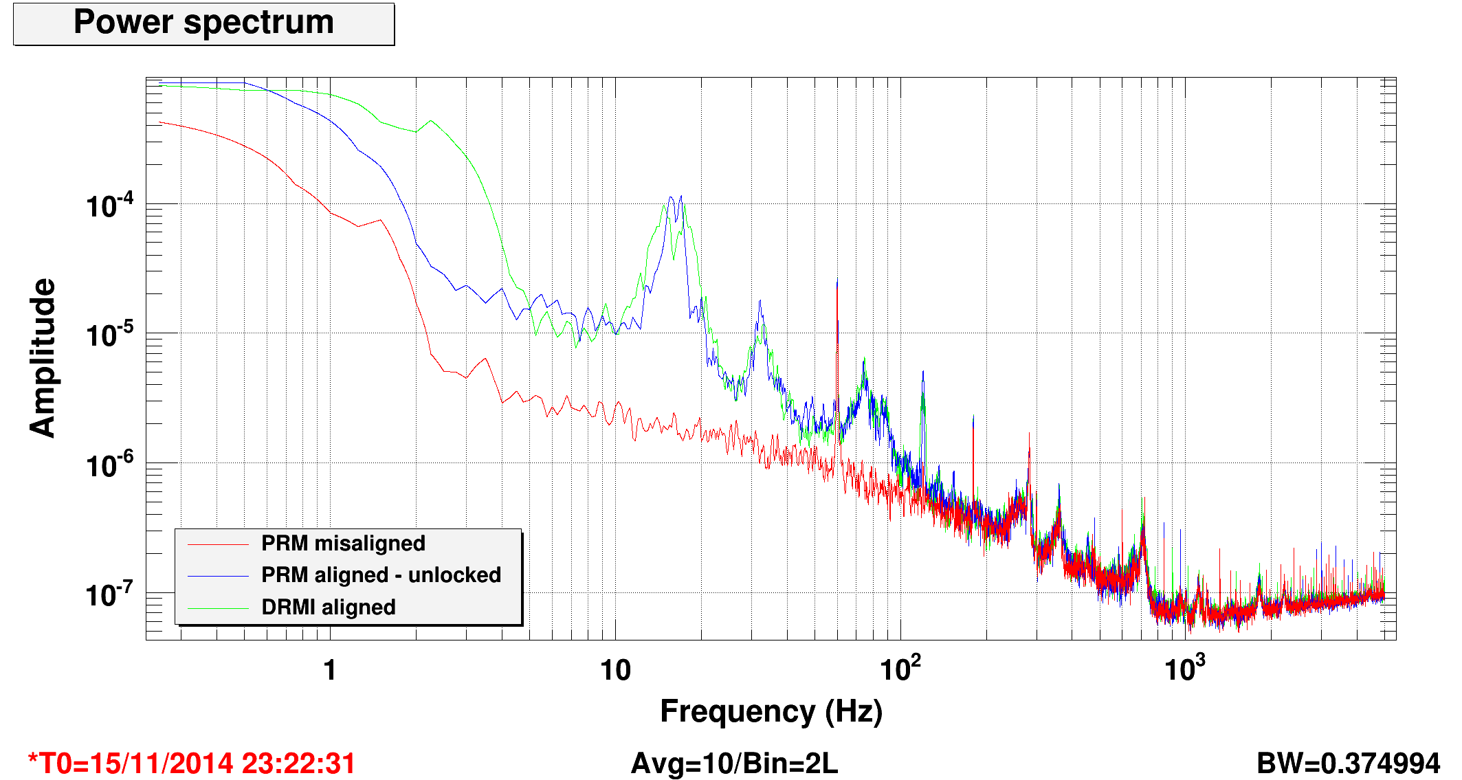
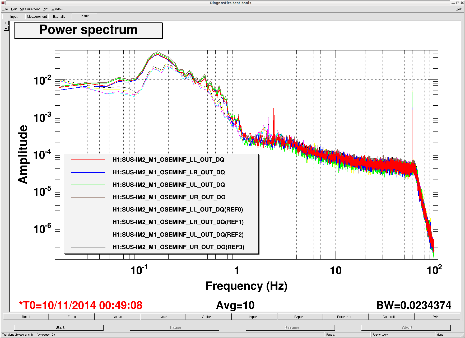
The first attached plot shows a comparison of the intensity noise as measured by the ISS diodes in three different configurations, in particular with the PRM mirror aligned or misaligned. Sadly, the intensity noise gets as much as 50 times larger when the PRM is aligned. The most prominent features are the 15 and 17 Hz peaks with harmonics.
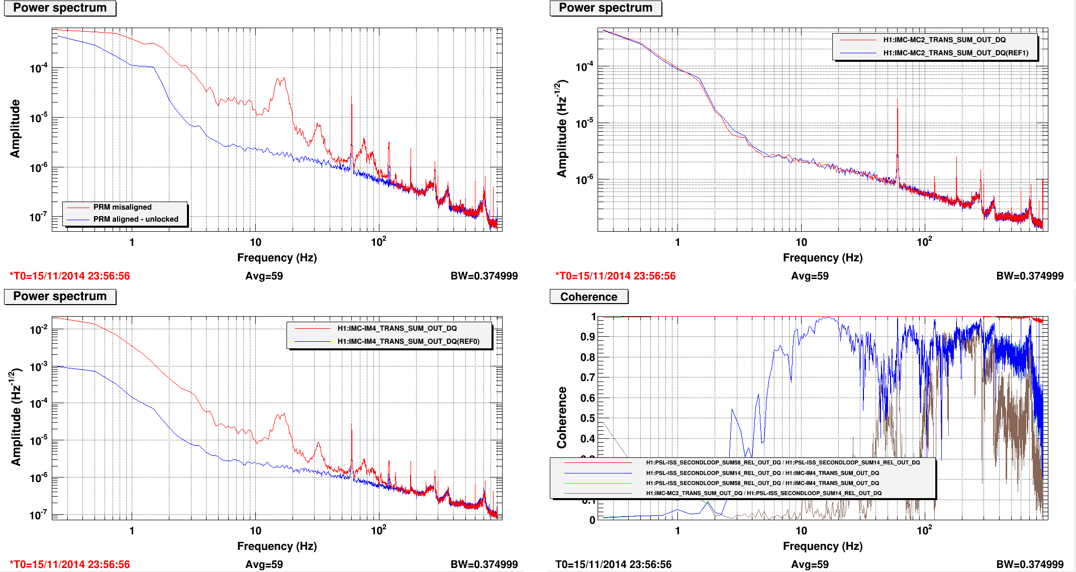
To add more bad news, look at the second plot. The increase of intensity noise is visible in IM4_TRANS and all ISS photodiodes (showing here SUM14 and SUM58 for simplicity). But it is not visible in MC2_TRANS, so it's not real laser intensity noise into the IMC. All the signals in the plot are calibrated in the same units of RIN.
This means that the PRM alignment does not introduce additional real intensity noise, but just sensing noise on IM4 and ISS diodes. The bottom right panel shows the coherence between different pairs of signals, when the PRM is aligned. SUM14 and SUM58 has very high coherence, so they see the same noise. Coherence with IM4 is algo good, while there is almost not coherence with the MC2 TRANS diode, as expected since it's not real intensity noise.
In summary, so far we know that:
- When the PRM is aligned, some stray / scattered light goes into the IM4 TRANS path and pollutes the ISS signals.
- When we close the ISS loop, we can get a good out-of-loop supression, since SUM14 and SUM58 are very coherent
- But this suppression will not be real, since it's coming from "sensor noise"
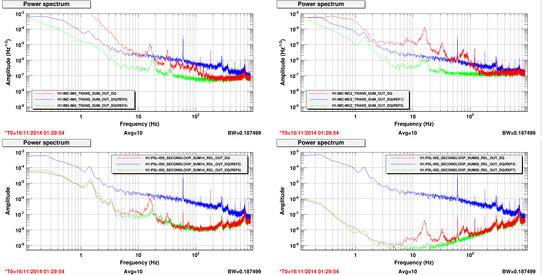
To test the latter conclusion, I compared the intensity noise as measured by MC2_TRANS, when the ISS second loop is closed and the PRM aligned.
In the third plot, the blue traces show the situation when the PRM is misaligned and the ISS second loop is open: all sensors agree on the level of intensity noise. The green traces then show what happens when the PRM is still misaligned, but the ISS second loop is closed: again the level of intensity noise is comparable in the four sensors. However, when the ISS second loop is closed, things get different: the ISS out-of-loop sensor shows some good suppression, but MC2_TRANS shows a large increase of intensity noise (up to 1e-4 /rHz).
So, we are re-injecting the ISS second loop noise (due to PRM reflection) into laser intensity. The ISS is not actually stabilizing the intensity noise, but making it worse, at least inside the IMC. We still can't exclude that the spurious beam is creating real intensity noise in the main beam out of the IMC, and therefore the stabilization is doing a good job to proide us a less noise beam into the IFO. We'll have to check using some other out of loop monitors from the IFO.
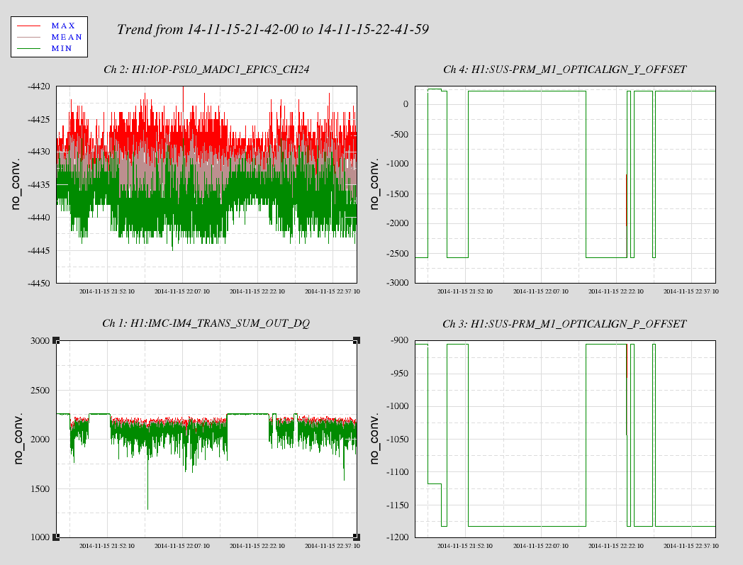
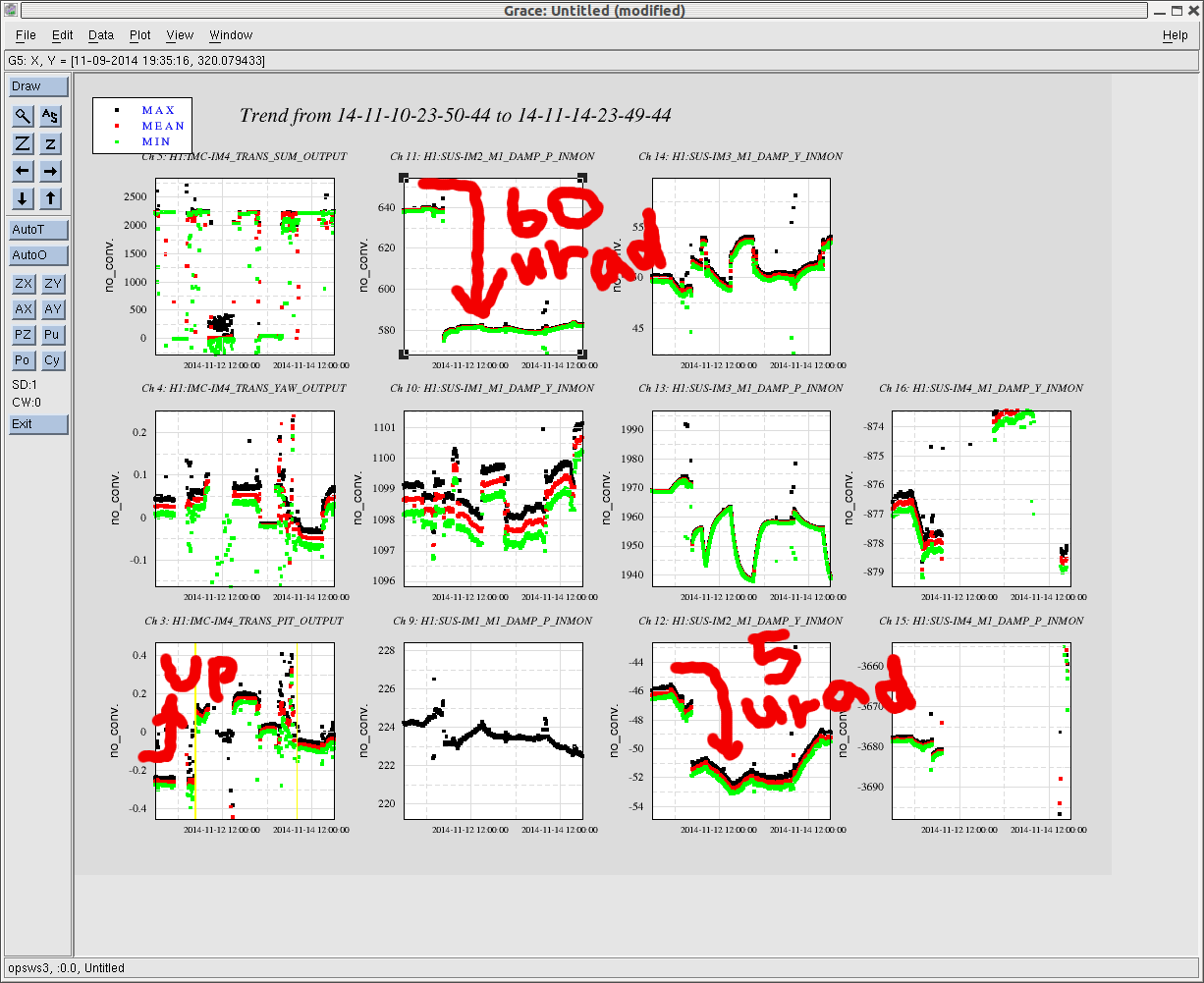
Some side comments. Both IM4 and the ISS diodes see a very similar excess of noise. Since they are quite far apart in the table, it seems that the spurious beam must be pretty well aligned with the main beam (can it be the reflection from the last Faraday waveplate, which is not well separated from the main beam?). Moreover, when the PRM is aligned, fluctuations of the power measured by IM4_TRANS can be as large as 20-30%, meaning that the spurious beam must have quite a lot of power.