K. Venkateswara
The tilt subtraction is working correctly now. The attached pdf shows the output of the tilt-subtracted super-sensor (in red) along with the GND_STS_X (in blue). The wind at EX is a measly 4-5 mph and in the wrong direction so there isn't much RY tilt. The red barely dips below the blue where the two sensors are coherent. It will be more apparent when the wind picks up a bit :)
Note that there are some odd features in the output of the filter above 7 Hz, which appear to be due to the low-frequency high pass filters, which foton doesn't like for some reason. I had to increase the high-pass frequencies to reduce this effect.
Also, note that most of what the STS is measuring below ~50 mHz is probably tilt but the tilt-subtraction isn't working well below ~20 mHz because we lose phase due to the high-pass filters and the finite d correction has not been implemented yet.
We will test this with the sensor correction next week when we get a chance.

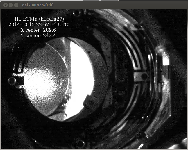

 I did not notice the snake!