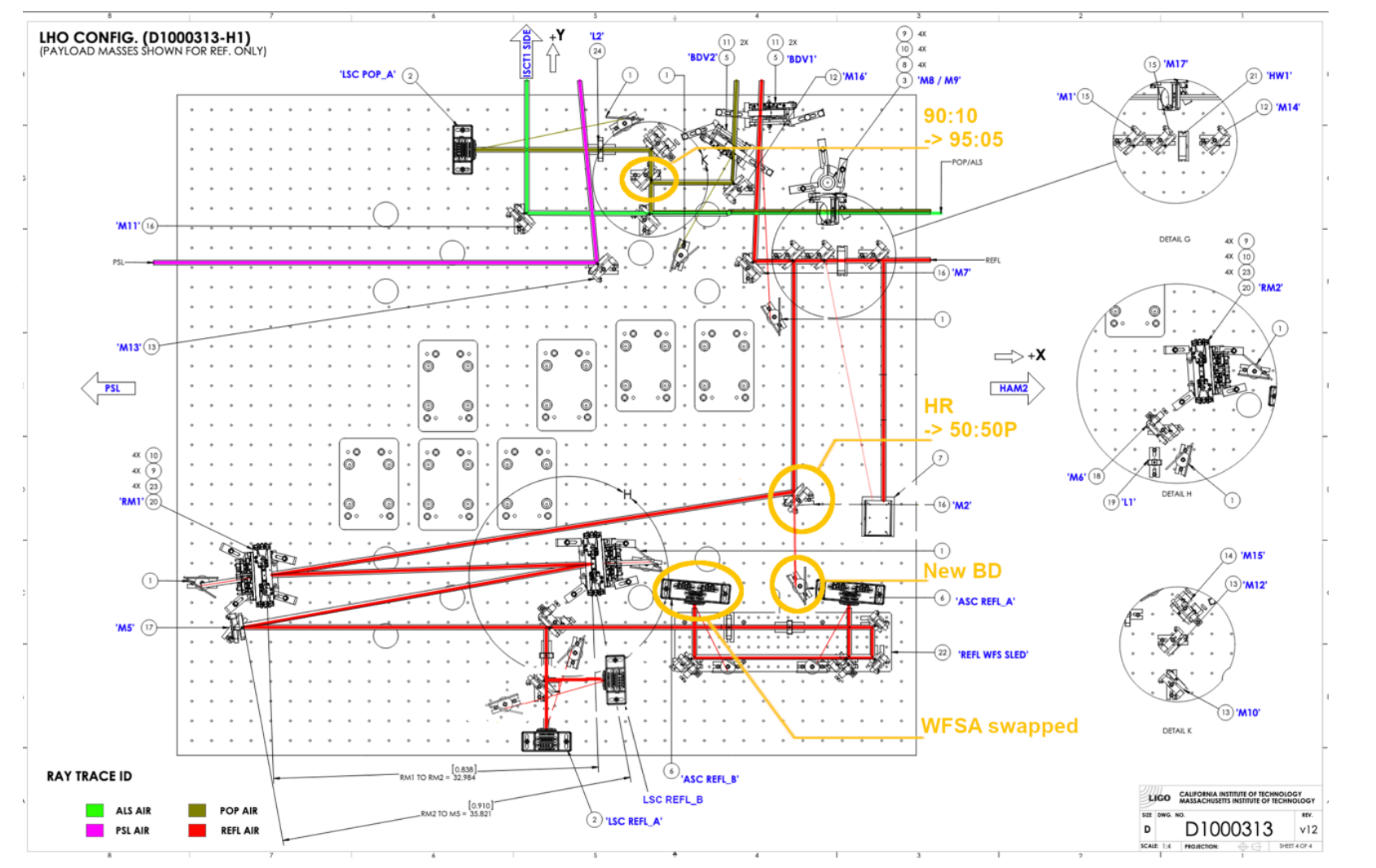
For mirror identification, see attached.
ASC-REFL_A replacement.
The new one is D1102004-V6 S/N 005 S1301248 (ICS ASSY-D1102002-001), the old one is S/N 012, S1301242.
With the old one, one of the differential output for DC4 segment failed and we've been using H1:ASC-REFL_A_DC_SEG4_GAIN=2 to compensate. With the new one, this didn't seem to be the case and we changed the digital gain to 1.
Daniel used the external RF injection ports to confirm that RF circuits are connected.
DC centering loops worked.
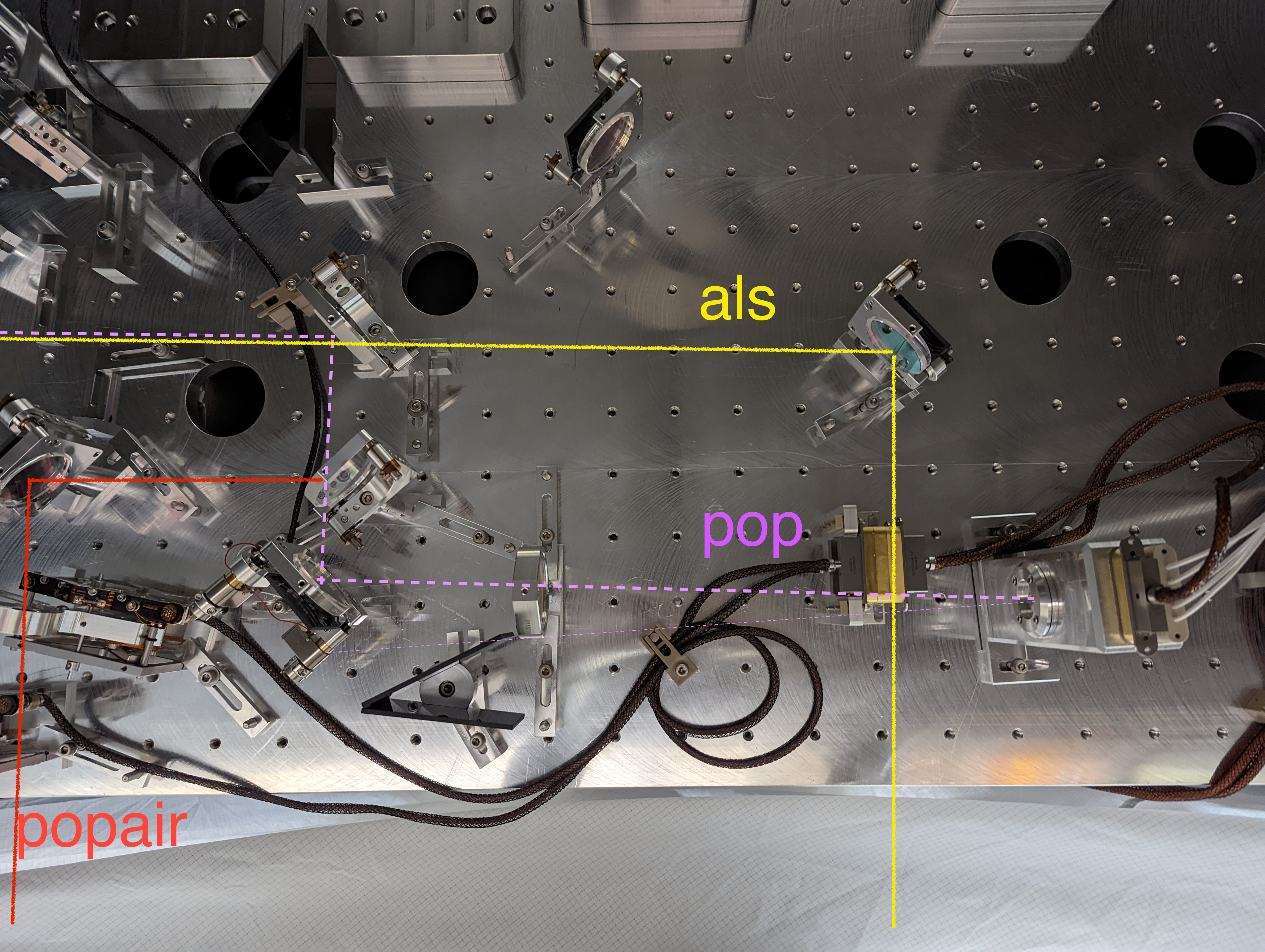
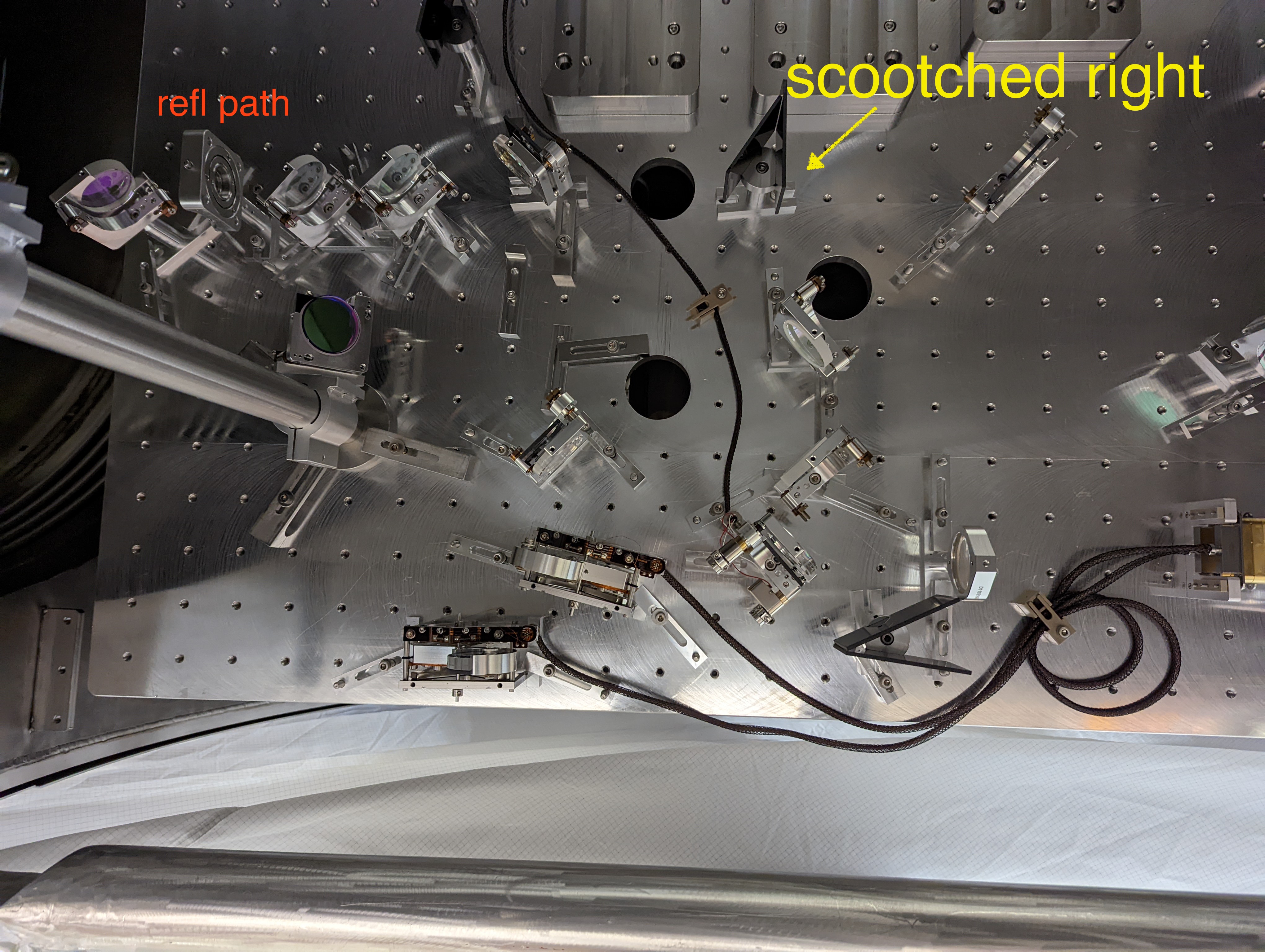
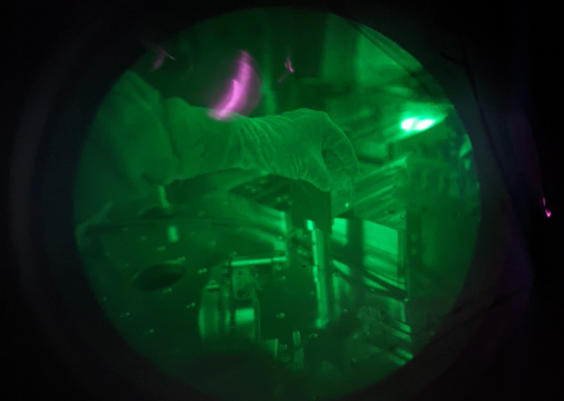
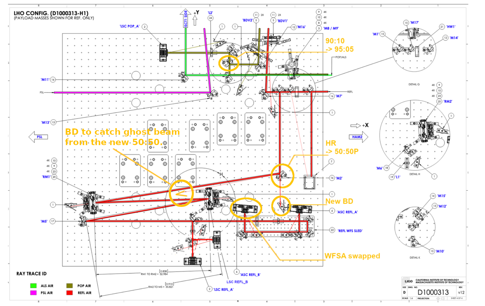
Beam dump relocation.
POP_air BDV reflection was hitting the corner of the V of the V-shaped beam dump.
ASC_REFL_A and ASC_REFL_B reflection were hitting the corner of the V of the V-shaped beam dump.
We moved these beam dumps so the beam hits one of the panels, not the corner.
We weren't able to see the LSC POP_A reflection. We might want to increase the power to 10W or so after everything is done so we can at least see the flashes.
We forgot to check the LSC REFL_A and REFL_B beam dumps.
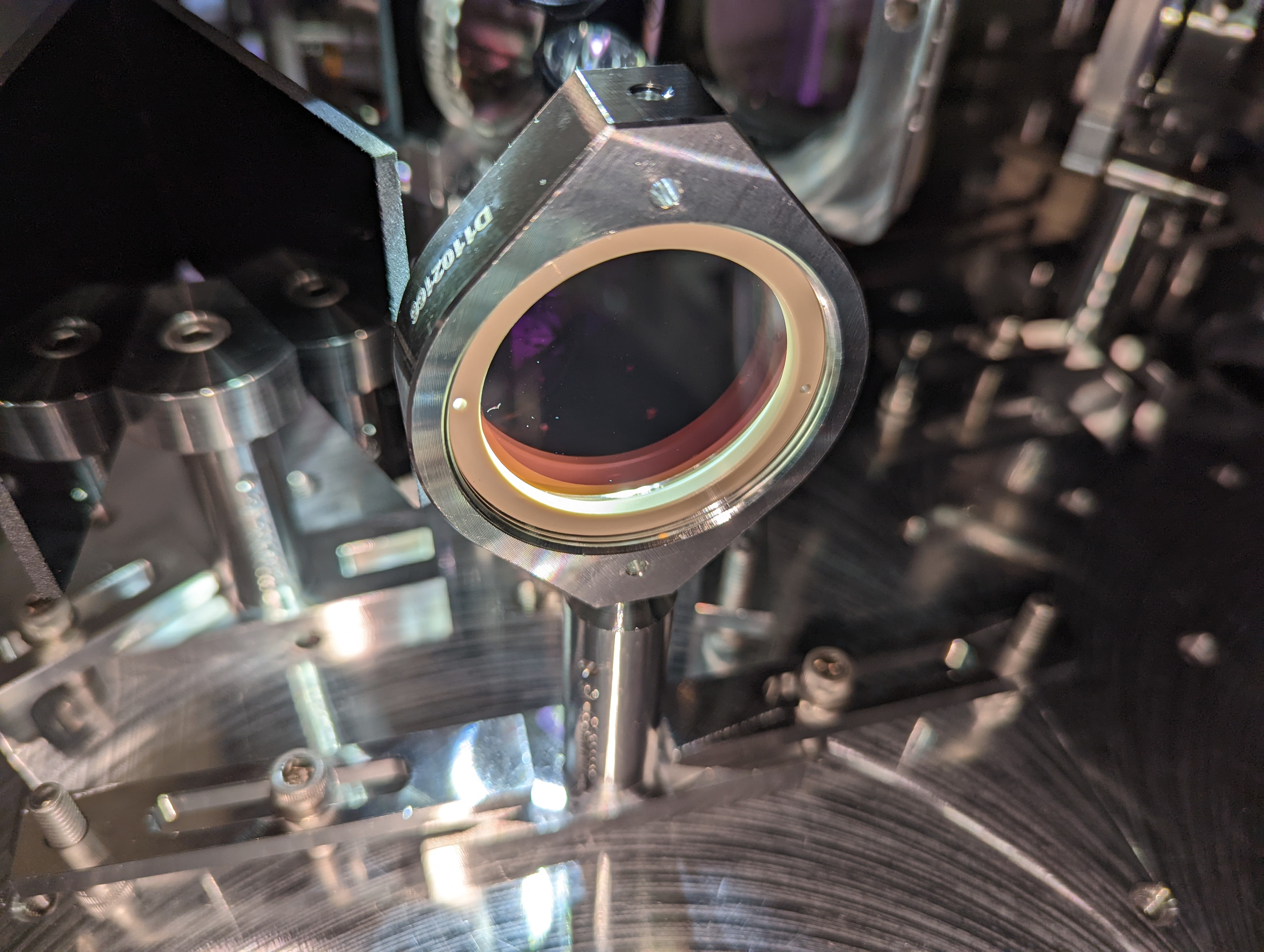
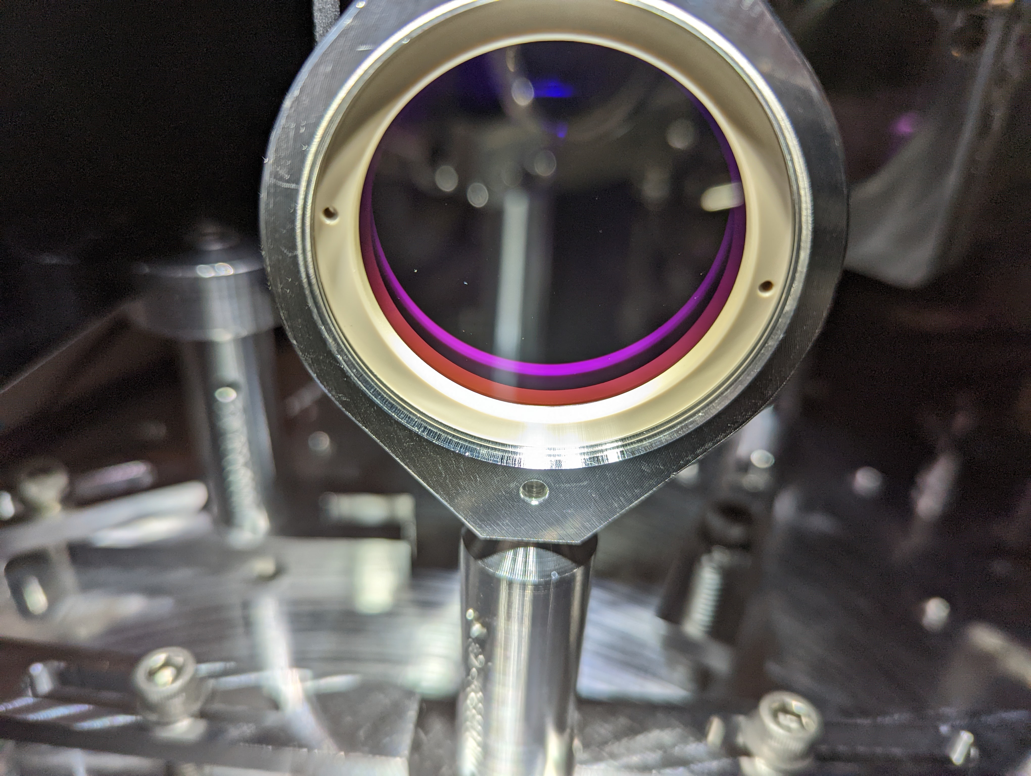
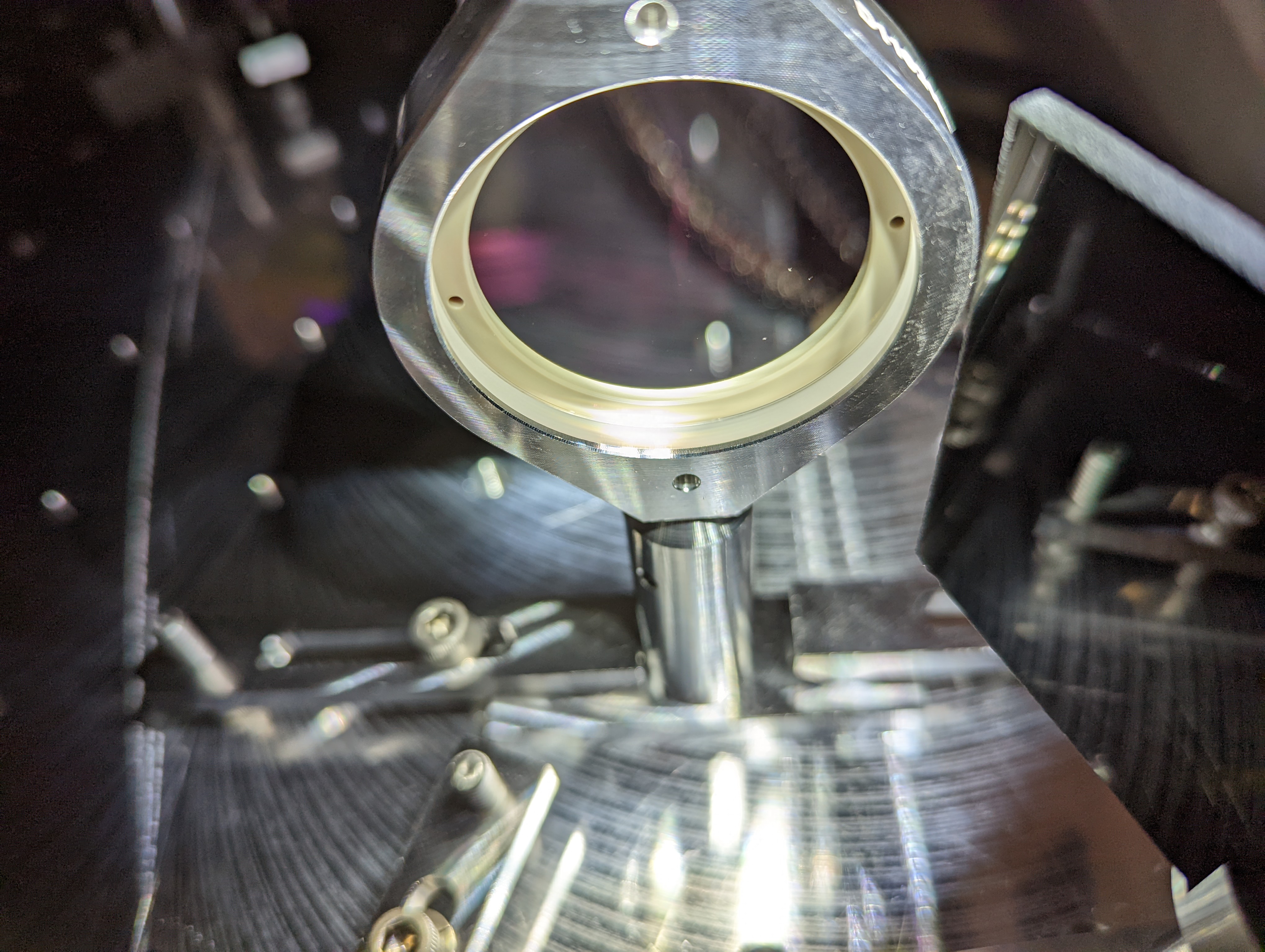
Swapping the optic in M2.
This is one of the corner mirrors in the REFL in-vac path, and we swapped the HR with the 50:50. We made sure that the wedge orientation is correct (thinner edge is close to [+X, +Y]) For the 50:50 using the laser pointer. Since HR doesn't have any wedge, we had to manually adjust M2 to restore the REFL path.
The AOI of that optic is not accurately known but I eyeballed it to be 50 degrees, and based on that I measured the reflectivity of the 50:50 in the lab before installation (alog 63404). It was about 43% reflection at 50degrees, 35.6% at 55 degrees.
In situ, we got 41.1%, so AOI is probably a bit larger than 50 degrees.
We put a beam dump to catch the ghost beam of the new optic.
Power measurements, continued.
We're done. If we can carrier-lock PRMI we could do more, but we couldn't.
Looking at the direct reflection of PRM when IMC_PWR_IN=1.001W, the power between M5 (2" HR at [-X,-Y] corner downstream of RM2) and M6 (REFL LSC-ASC splitter) is 5.96mW after we swapped the optic.
At See Craig/Ryan's comments.
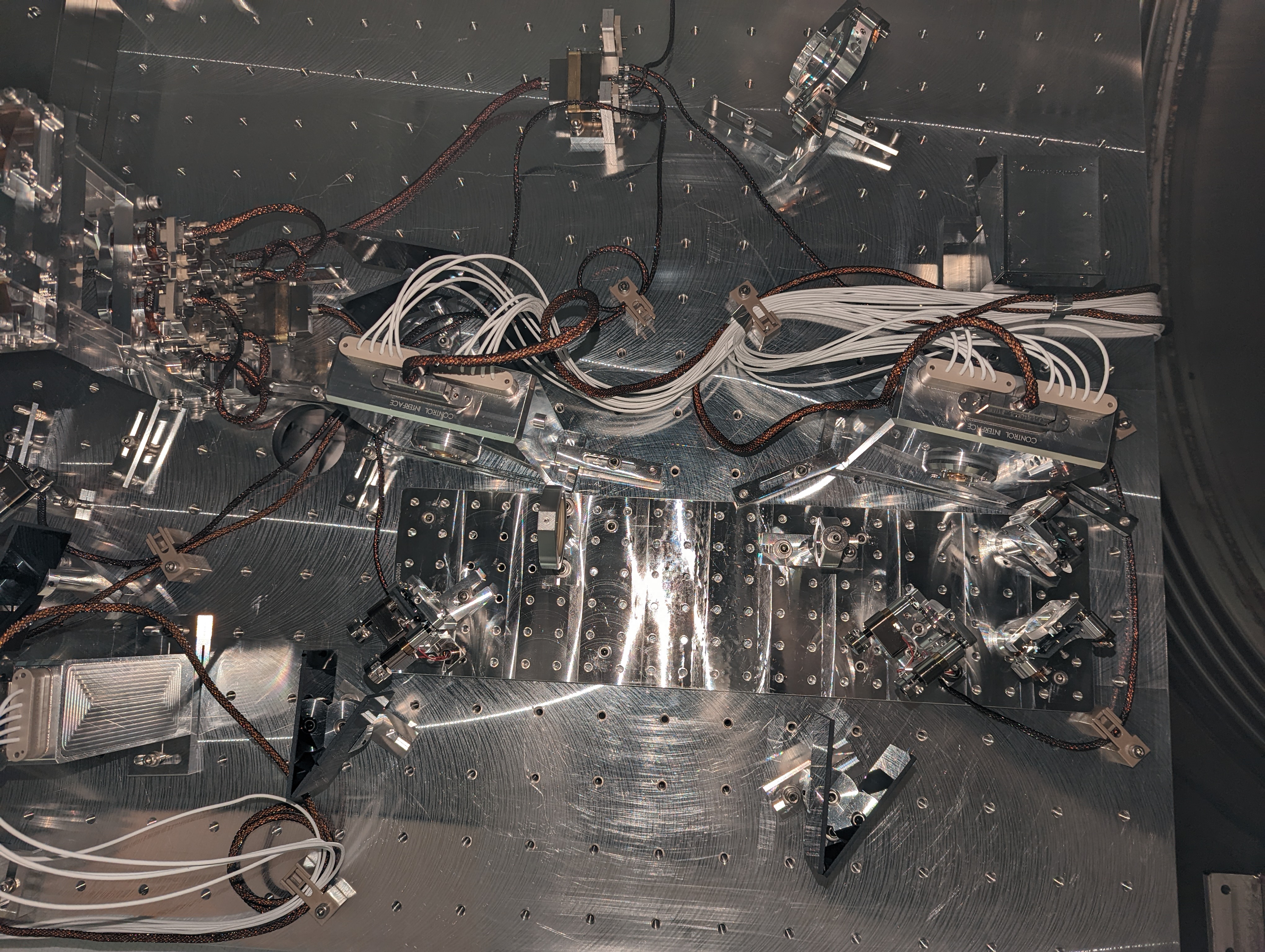
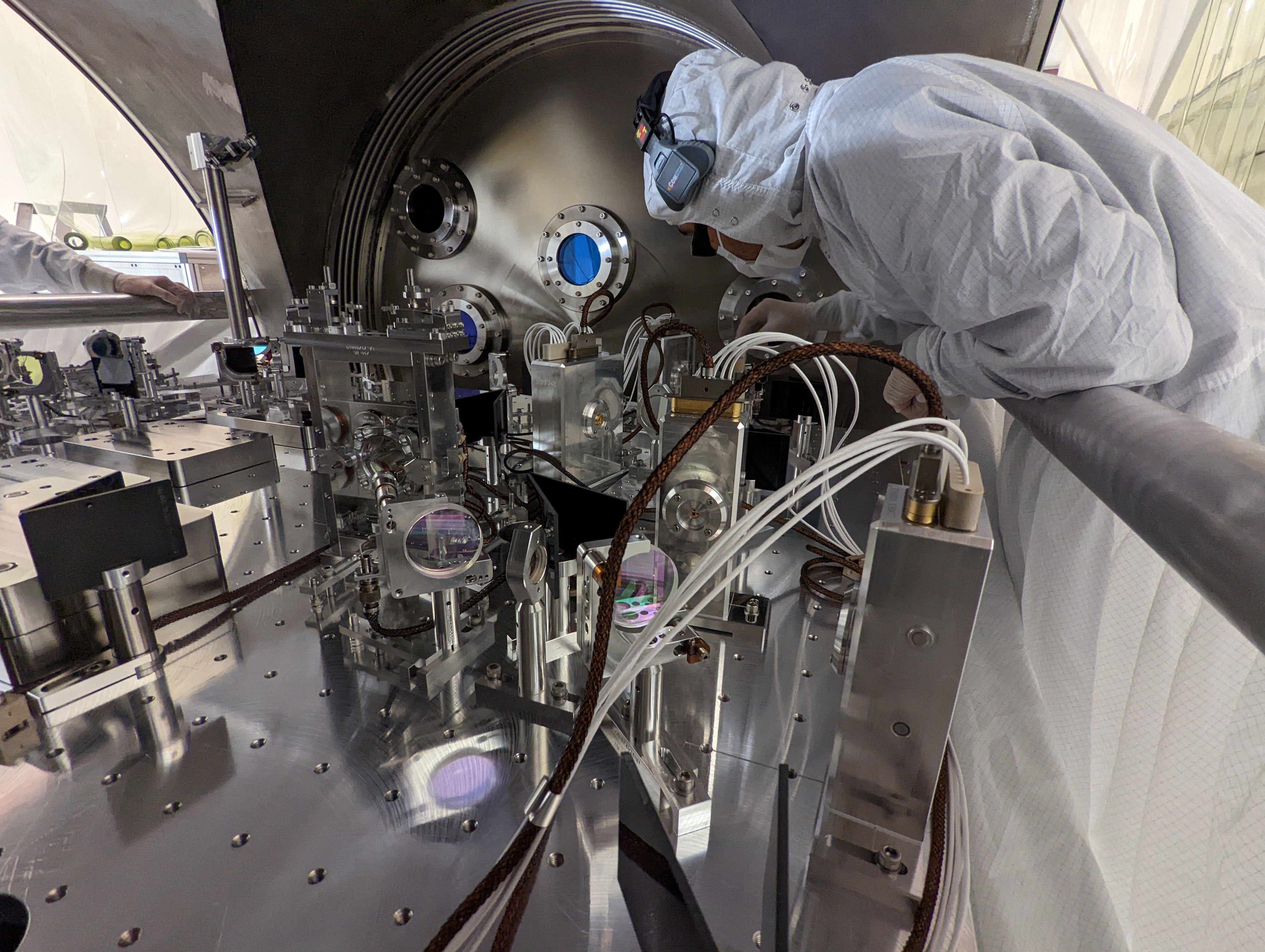
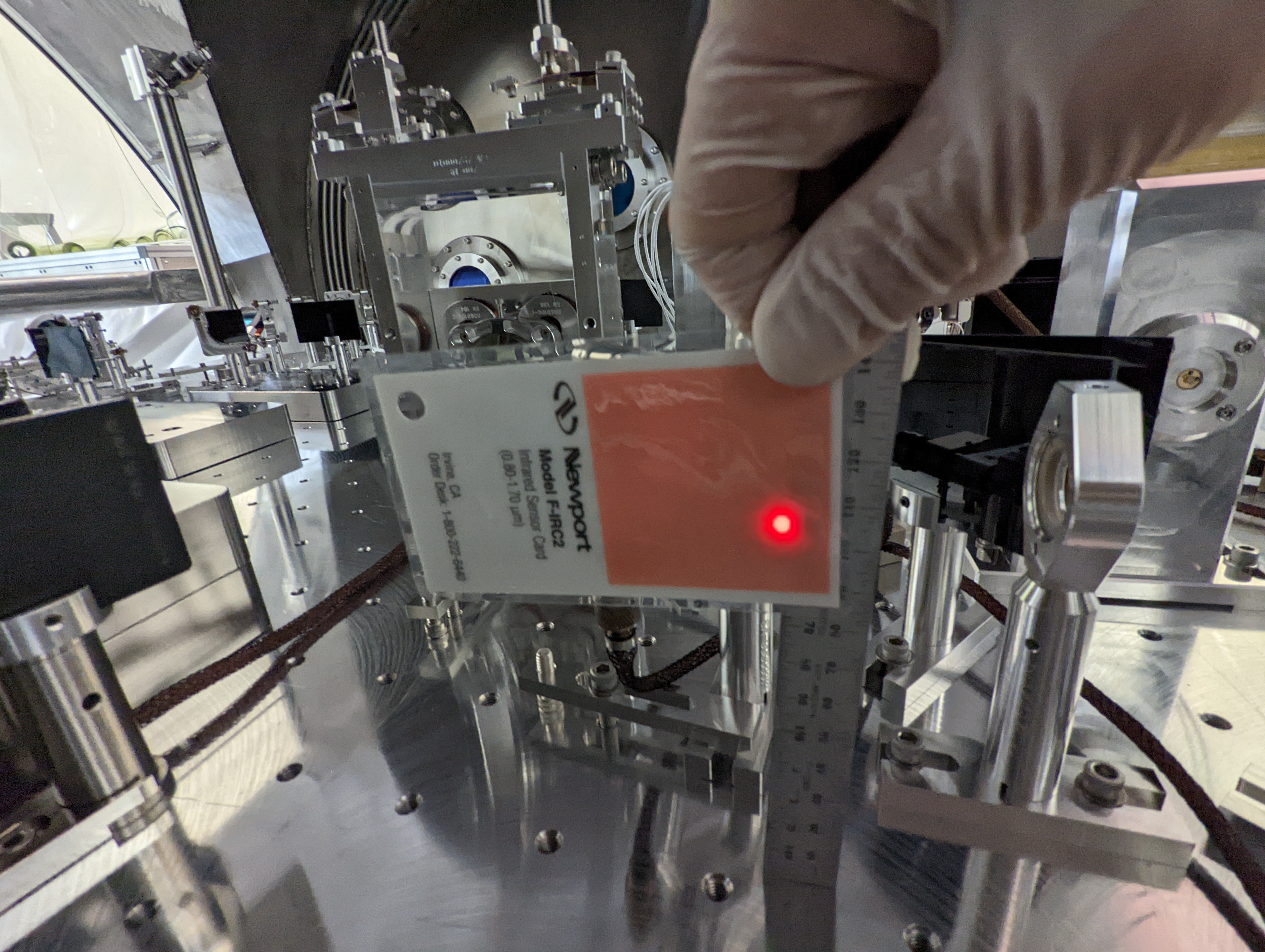
Clipping check in REFL path.
Nothing was clipping in the REFL path, but the beam was pretty high on M5 (that's the 2" HR at [-X, -Y] corner), M6 (ASC-LSC splitter), L1 (1" lens in front of LSC REFL sensors) and 2" lens on the WFS sled.
The beam height was ~105mm in front of M6 (see Georgia's picture), that's ~3.4mm higher than nominal, and the beam looks uncomfortably high on L1 because of the smaller aperture but it's not clipping.
We're leaving it as is because we don't want to touch the WFS sled and the only quick solution is to make the lens higher using a shim, then use M6 so steer the beam down on the LSC sensors.
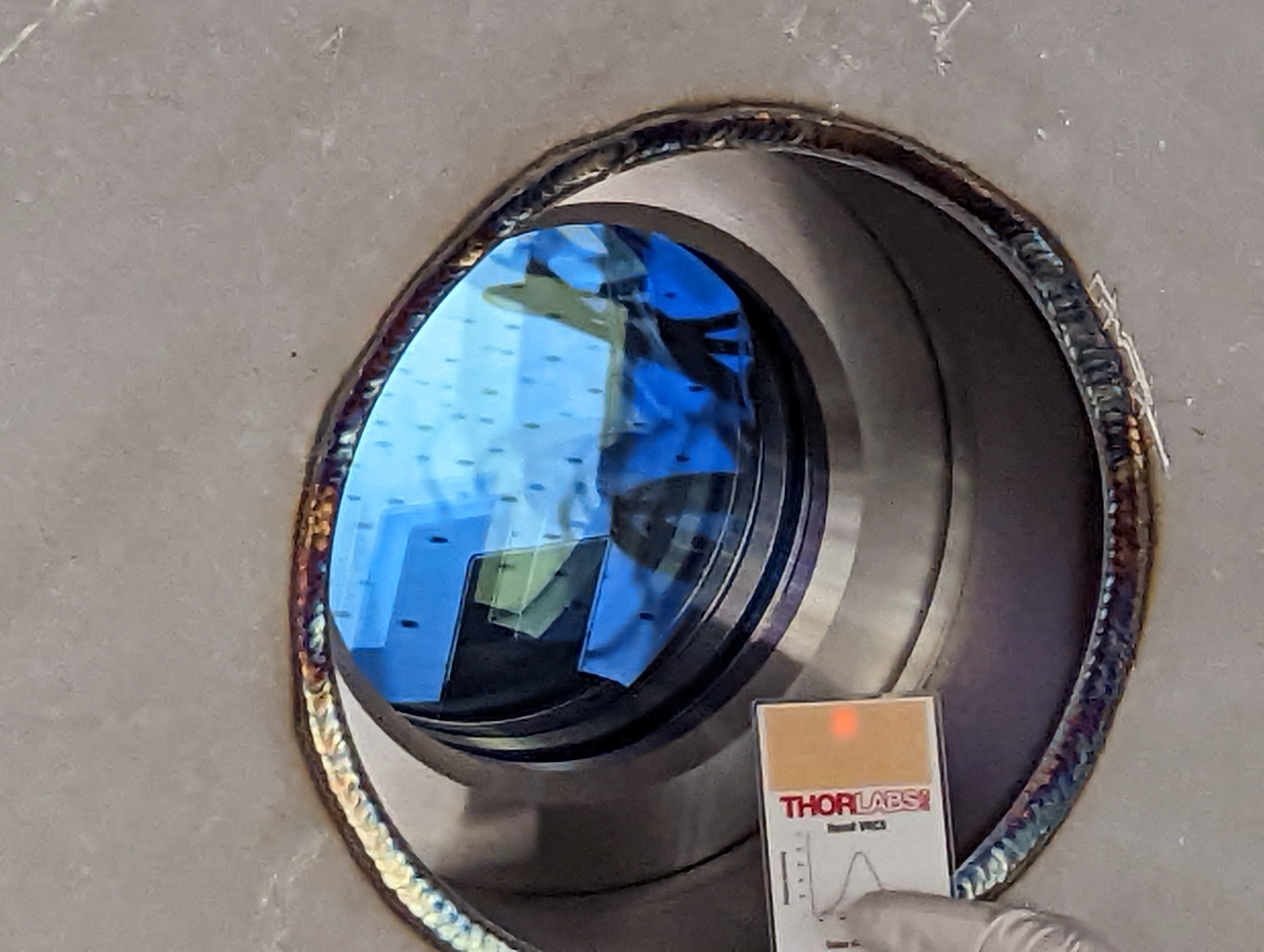
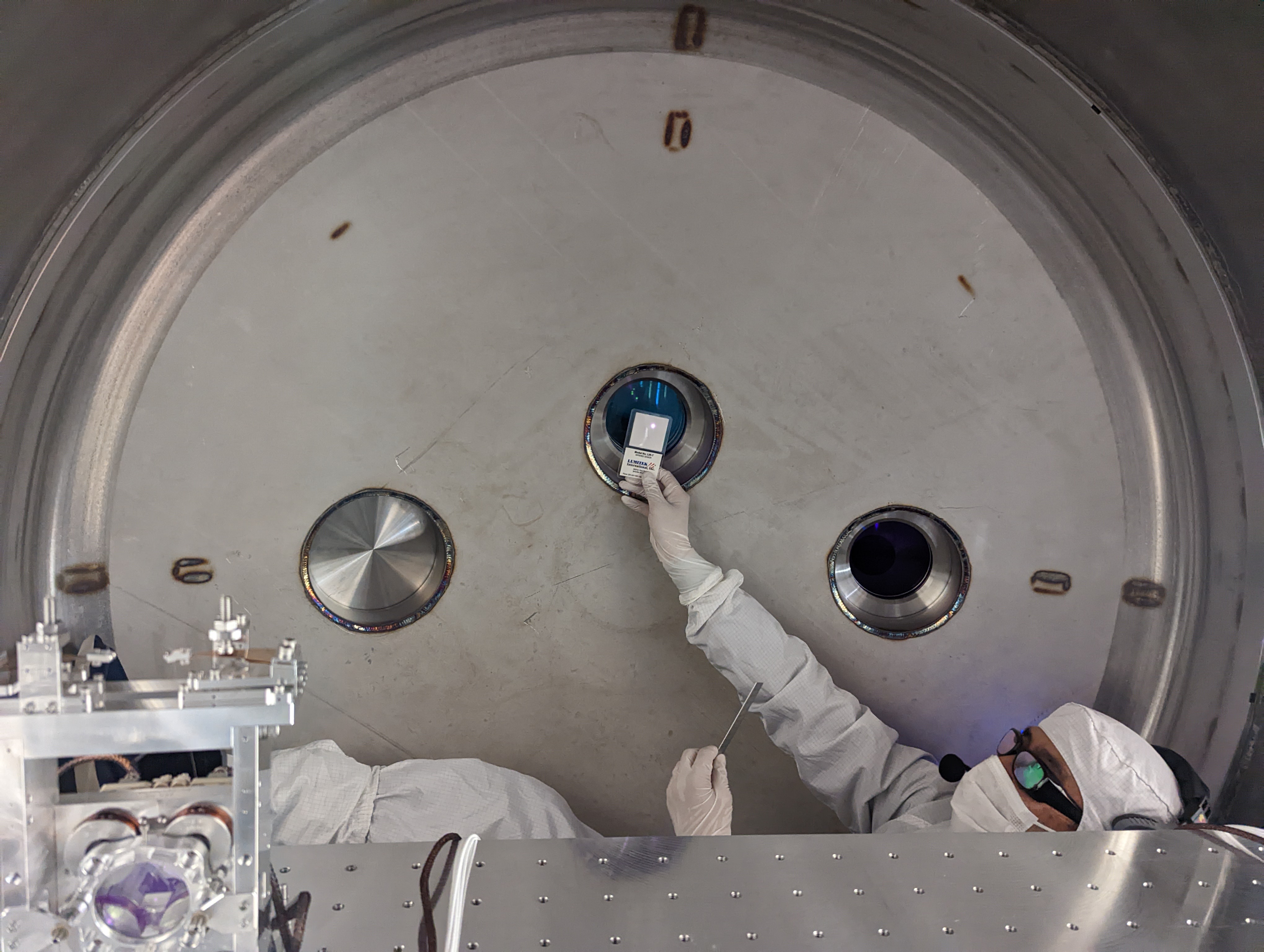
Searching for the ghost beam of the main septum viewport.
The main PSL beam is reflected by the AR of the HAM1-HAM2 septum viewport and land inside the nozzle of the PSL-HAM1 viewport at around 4 or 5 o'clock position viewed from inside the chamber. See Georgia's pictures. We haven't done anything yet, we need help from people to assemble and install nozzle baffle.
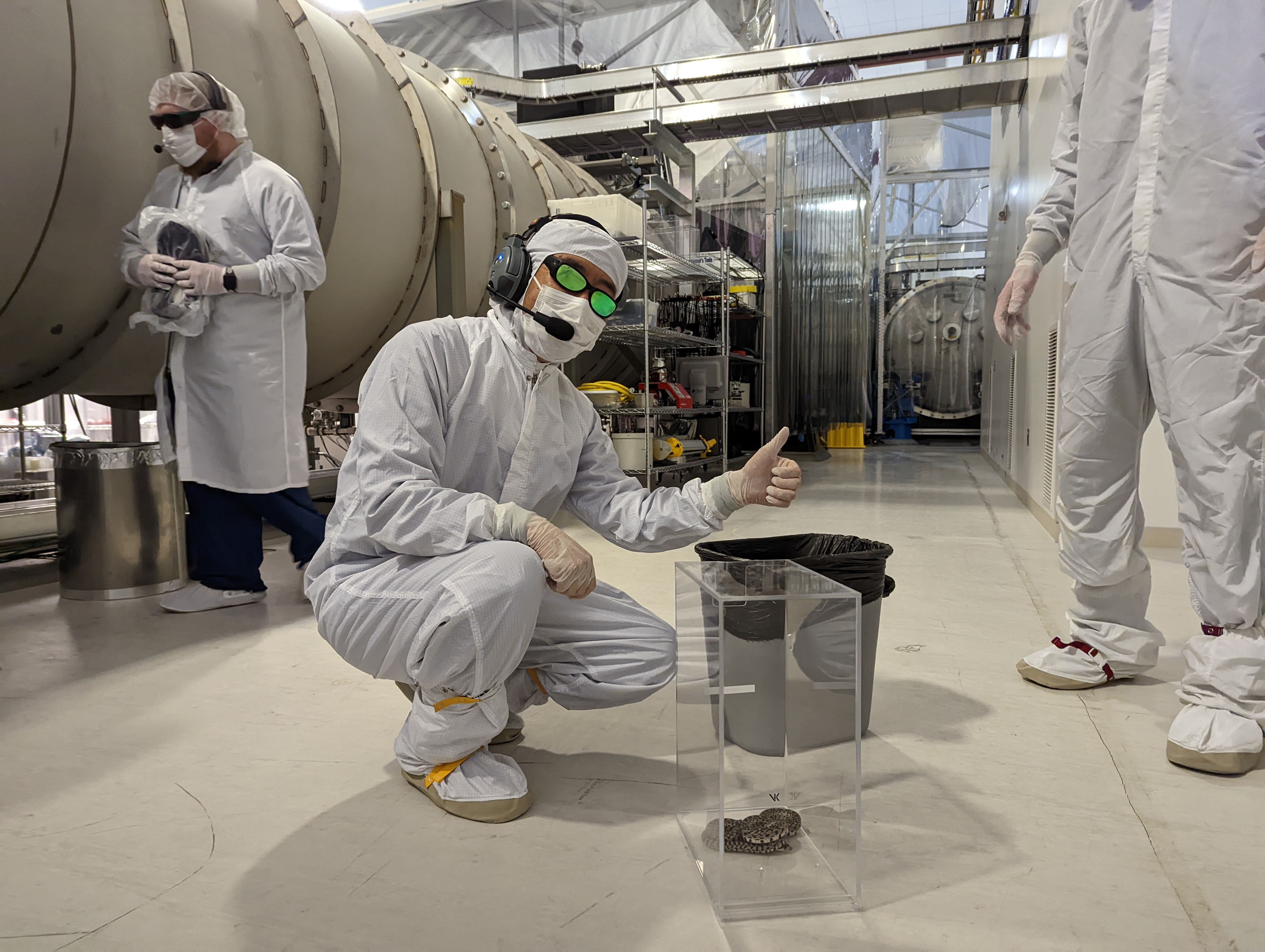
Catching a snake.
That was big.