LVEA is LASER HAZARD
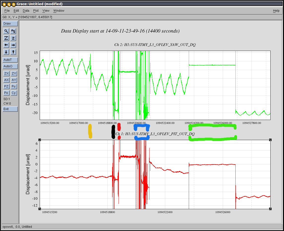
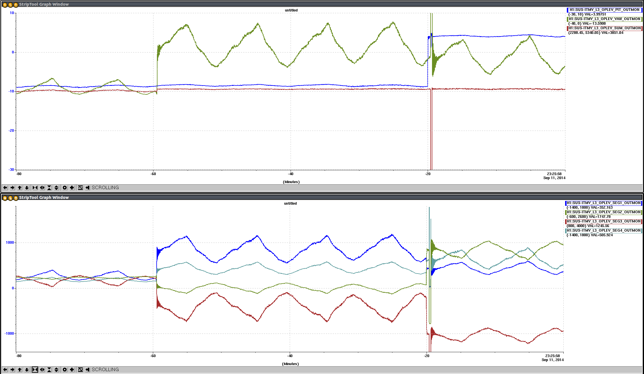
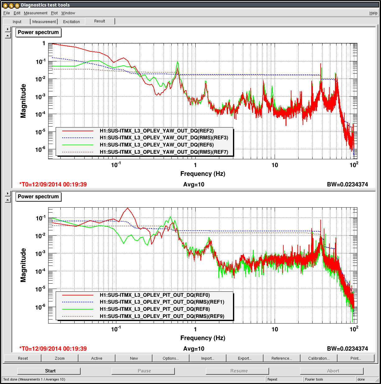
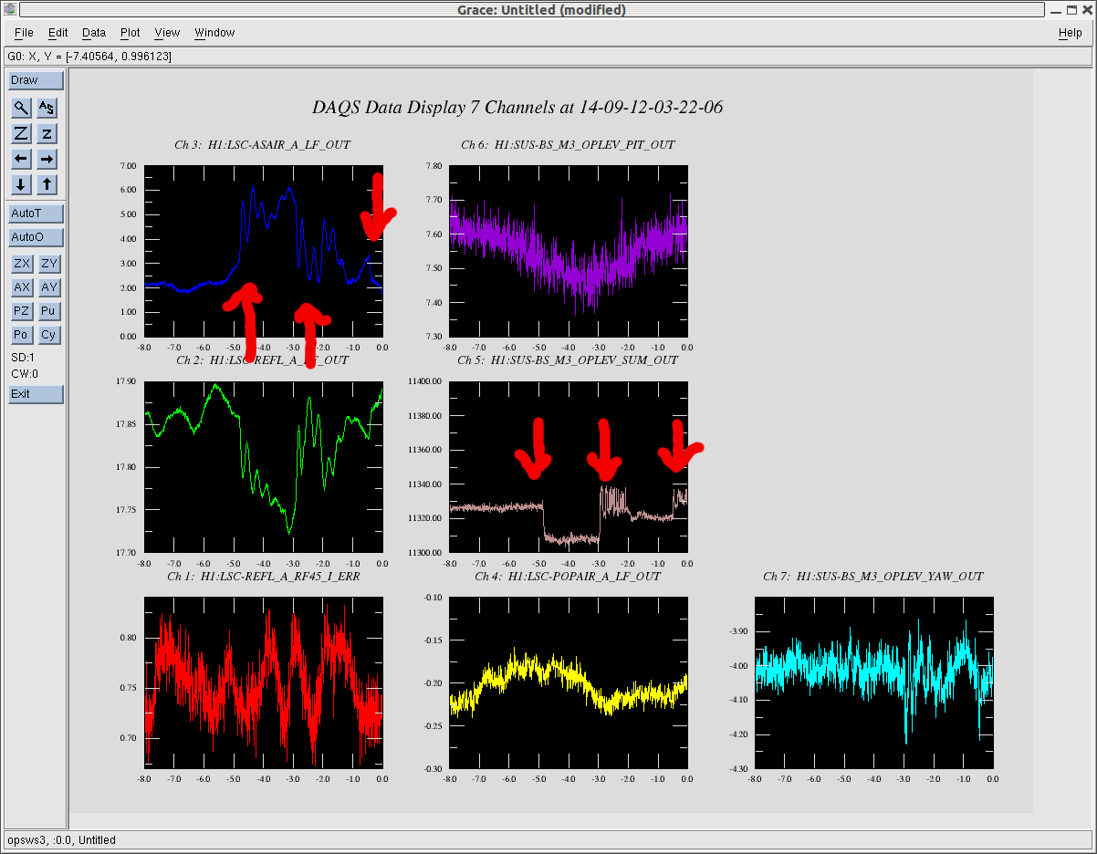
Op Lev - ongoing investigation of ITMY OpLev
TCS Install - no one present to report
Vacuum - No one present to report
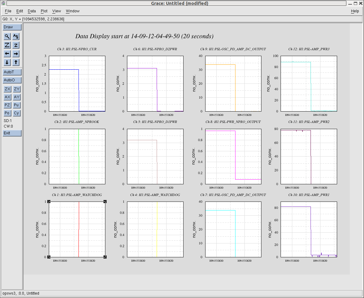
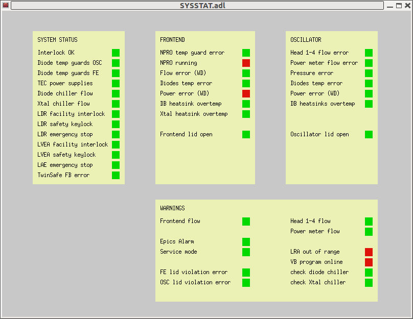
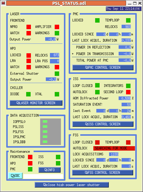
P King - would like to pull cables for ISS. FE LASER watchdog tripped last night. Comments made about aginf NPRO. misc: H1 LASER 'accepted' about 3 weeks ago.
F Raab - suggested some sort of "dashboard" as a visual means to monitor which (sub)systems have passed acceptance testing
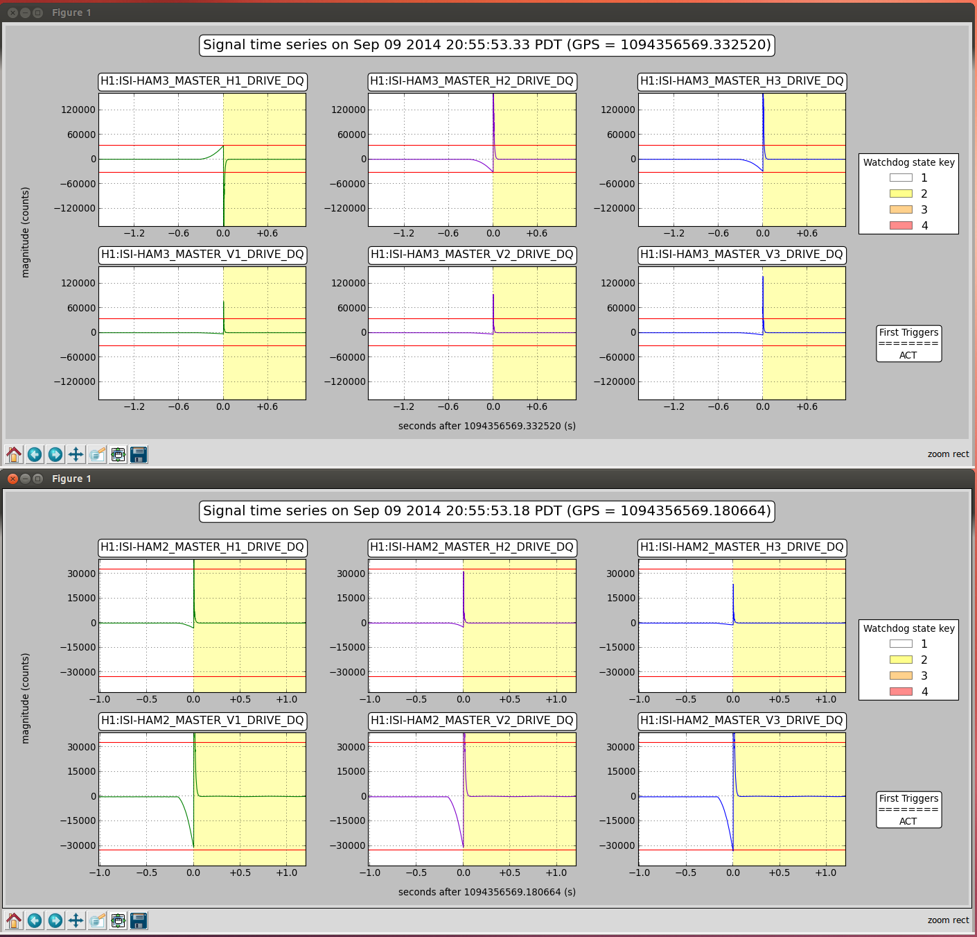
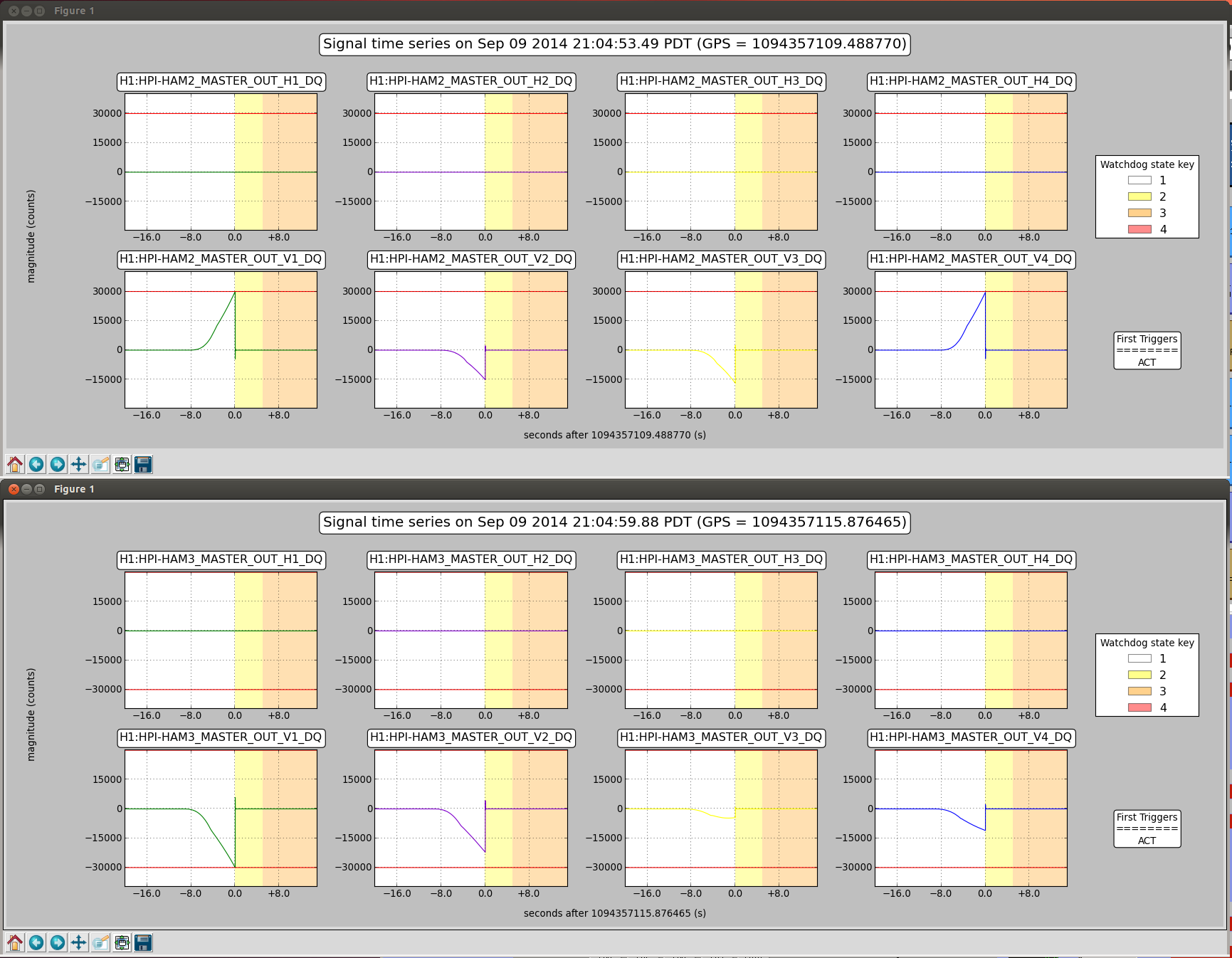
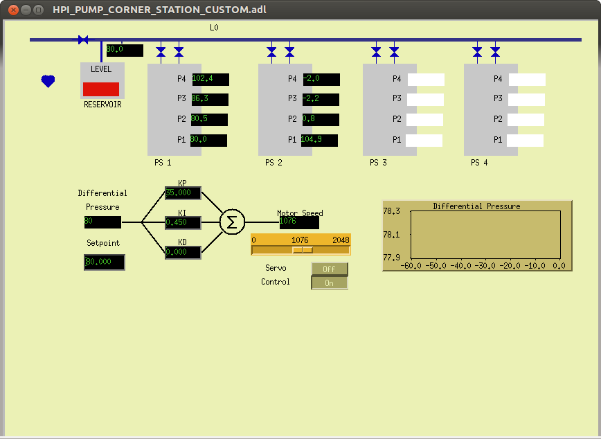
Seismic - reported that excess moin in ITMX has been remedied and there will be further investigations into the reason(s) There was a discussion about the 'global' condition of HEPI/ISI world akin o the aforementioned "dashboard"
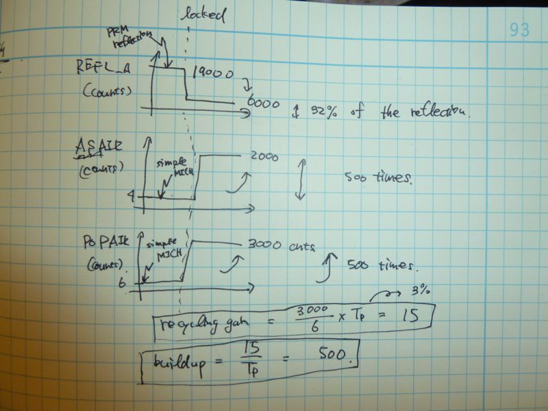
Commissioning- Keita will be working on getting the SLED QPDs aligned in the morning and then working on the PRMI in the afternoon to coordinate his activities with the ongoing Seismic testing/investigations.