gerardo.moreno@LIGO.ORG - posted 16:20, Friday 22 August 2014 (13572)
Ops Shift Summary
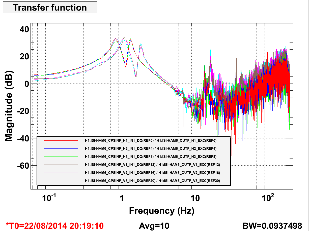
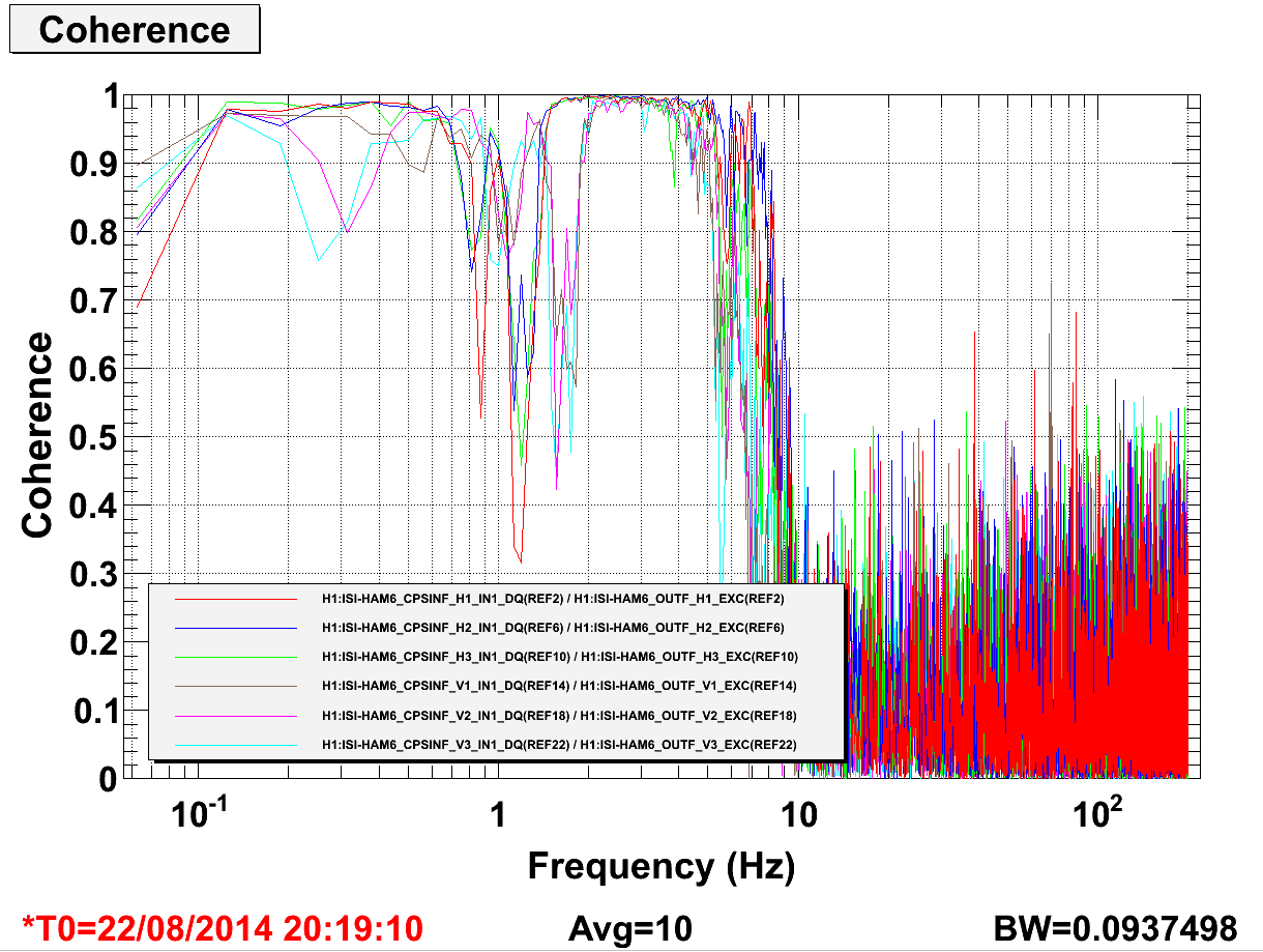
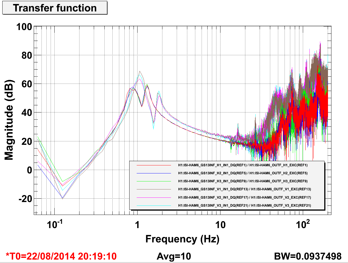
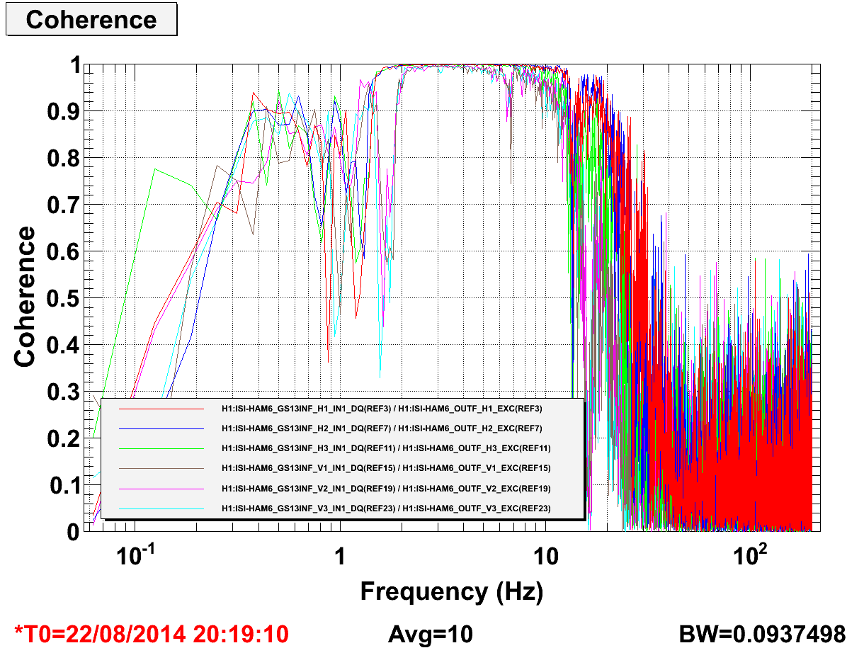
- 9:20 am, Jim W. to CS VEA, HAM6 work unlock ISI.
- 9:40 am, Anaud and Filiberto to CS VEA, HAM5 work.
- 11:00 am, Krishna to X-End VEA, retrive equipment.
- 11:13 am, Filiberto to X-End VEA, power LHO's tiltmeter.
- 12:00 pm, Fred and visitor to CS VEA, tour.
- 12:25 pm, Kyle and Gerardo to X-End VEA, to power ion pump 12.
- 1:00 pm, Karen to Y-End station, clean.
- 1:47 pm, Sheila and Borja, to X-End VEA, station is now laser safe.
- 3:30 pm, Sudarshan to visit both Y-End and X-End station for PEM work.
- 3:51 pm, Filiberto, Manuel and Borja to Y-End VEA, ESD power measurements.