Alexa, Dan, Koji, Sheila, Stefan, Kiwamu,
Today we spent some more time on alignment of the IMC with the use of the WFSs loops. After some struggling, we eventually could close all the loops stably. However, the ASC loops tend to drift on a time scale of 30 min.
In parallel to it, we made a first attempt of the ring down measurement. The data did not make sense this time. Ongoing.
IMC alignment:
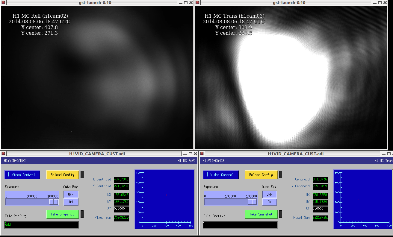
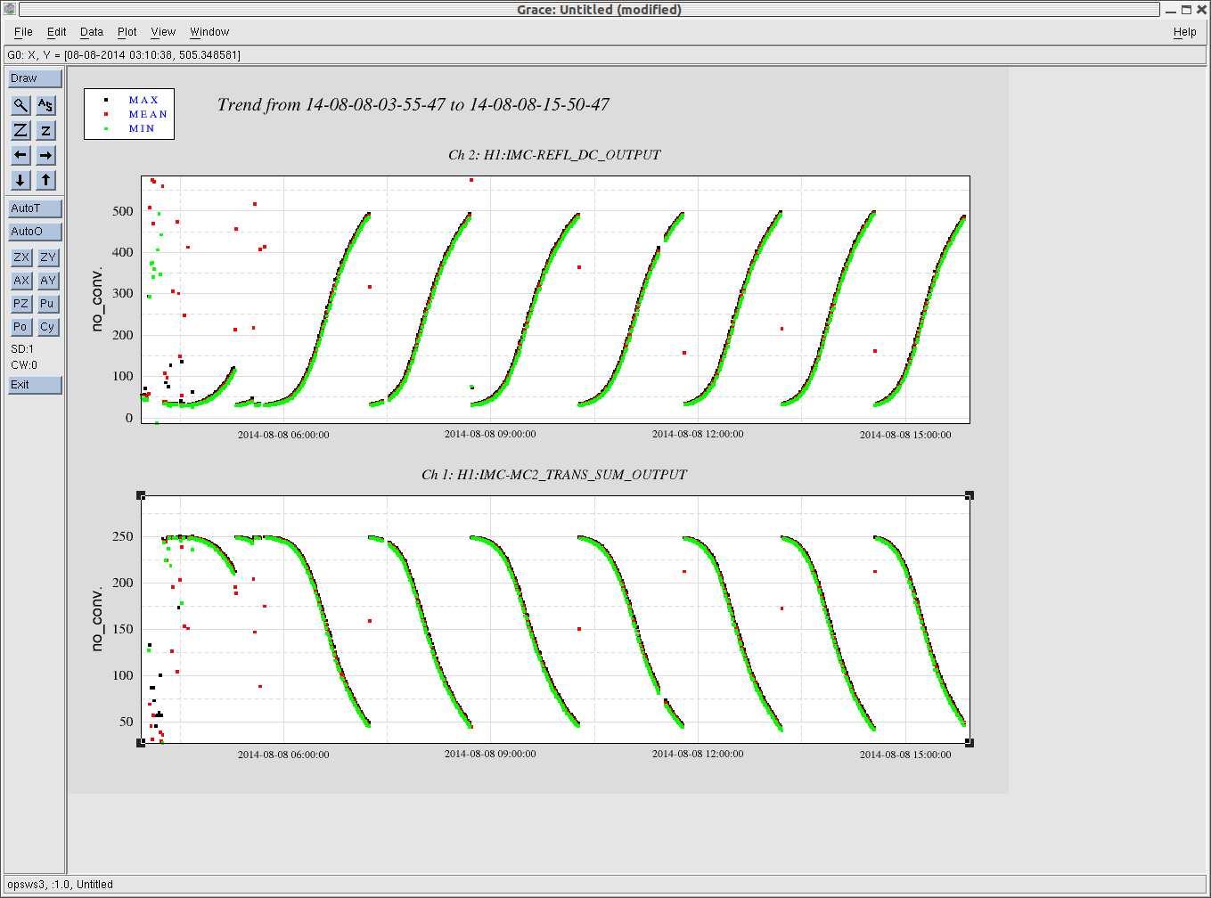
Our original hope was that once the WFSs were centered, they should be able to servo the IMC to a good alignment. However, it turned out that stably engaging the ASC loops were very difficult for some reason. The first issue we noticed was that the MC2 trans QPD did not show a reasonable signal. It looked all noise and indeed changing the whitening settings did not change the shape of the noise. This indicated some issues in the analog circuits. Stefan and Sheila went to the rack and found that a number of cables were unplugged. Also, they found that the whitening electronics were turned off. So they plugged the cables back to the whitening box and powered up the whitening box. This recovered signals on the MC2 trans QPD. This then allowed us to close the 'DOF3' loop which is the centering servo for the MC2 QPD.
However, we were still having a difficulty in closing the rest of two loops in the IMC ASC. They use the signals derived from the WFSs. The symptom is that the error signal looked too big even though the loops are closed. It looked as if the loop is not suppressing the signals. Acutually, keep running the ASC loops made the power buildup and visibility worse on a time scale of 30 sec or so. We made sure that the dark offsets were successfully removed and centering on these WFSs were fine. But, no success.
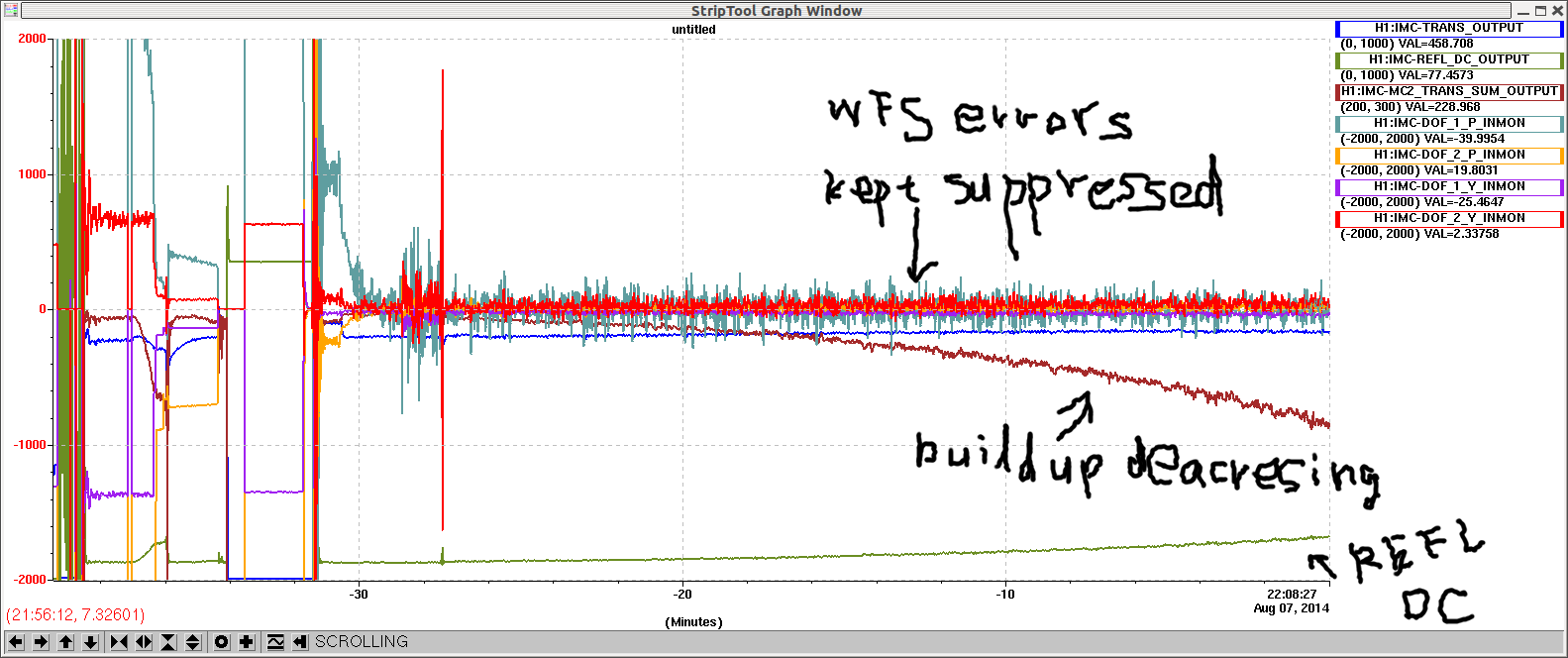
After people left, I did some more investigation on the ASC loops. Since I did not like the beam shape in the reflection camera, I went to the table and checked out the beam. I found that there was a ghost beam not being dumped and going into the WFSs. I narrowed the aparture of the iris that was infront of the REFL RFPD such that it catches the ghost beam. Then I digitally removed the dark offset from all the WFS segments and tried closing the ASC loops again. The loops stayed stable for approximately 10 min. However then it started degrading. See the attached. I am not sure why, but I am worried about RFAM. I am leaving the ASC loops running for the night to see the long term stability.
Ring down measurements:
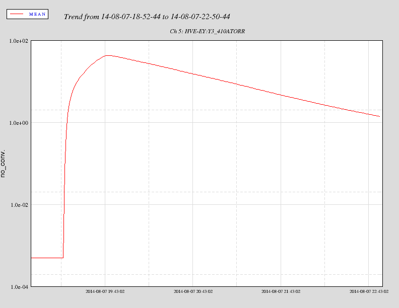
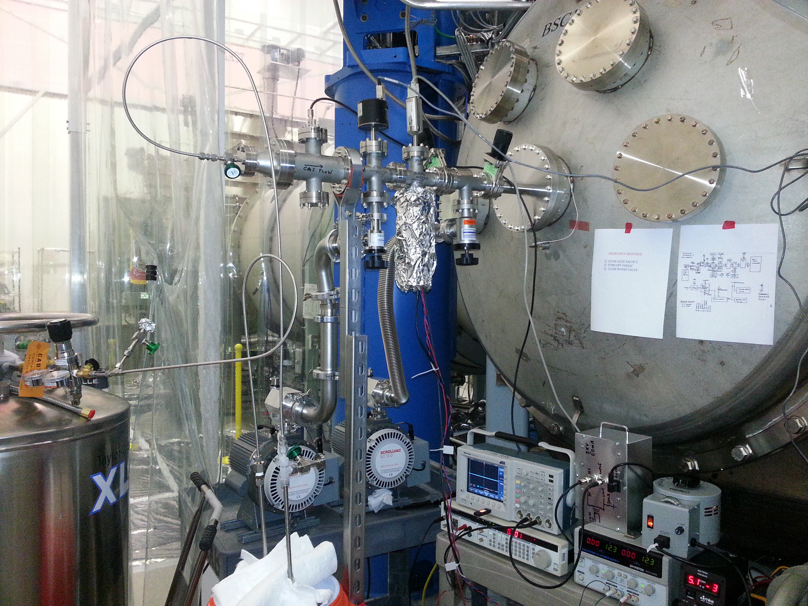
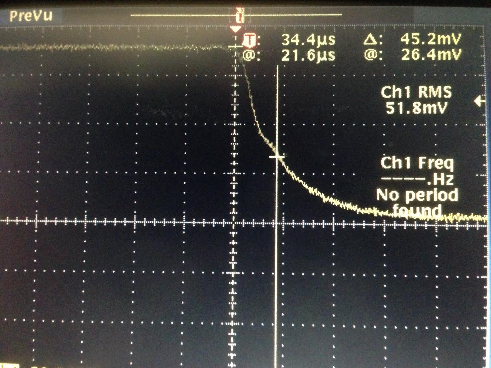
We also spent some time trying to measure the cavity decay time (storage time) in order to estimate losses in the cavity. We tried various ways of shutting the control or light off, but ended up with switching the polarity of the fast signal in the IMC board. This is the same technique as Livingston did recently (LLO 13748). We were expecting to see something like 17 usec 1/e decay time, but the measurement tended to give us about 35 usec which is twice bigger than the expectation. At this point, it is unclear why the decay time is such long. The attached is a picture of the raw data displaced on an oscilloscope. The PD is Thorlabs, PDA100A on the IOT2L table. The bandwidh is 2.4 MHz according to the data sheet which should be fast enough for this measurement.
It maybe independent, but we know that this transmitted light is largely clipped (seemingly more than 20% of its total intensity) somewhere in chamber before it comes out to the IOT2L table. So we are interested in repeating this measurement at a different port. Maybe at REFL or IOT2R. The measurement is therefore ongoing.