david.barker@LIGO.ORG - posted 10:40, Sunday 03 August 2014 (13174)
CDS model and DAQ restart report, Saturday 2nd August 2014
no restarts reported
no restarts reported
John, Gerardo,
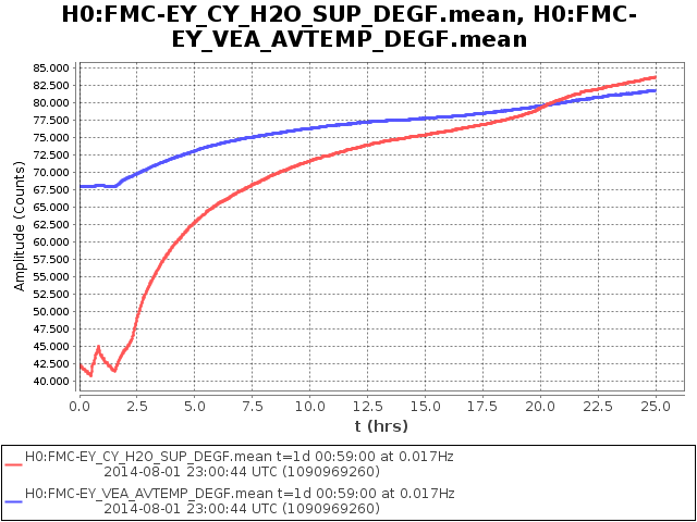
Gerardo was at LHO today inspecting viewports and while in the control room noticed temperature alarms at the Y end.
He found the chilled water temperatures to be way out of range (80F instead of 40F) He was able to start the second chilled water pump from the control room but unfortunately this did not start the second chiller as expected.
At the Y end chiller yard he was able to reset the second chiller and successfully start it.
Temperatures are now returning towards normal. The trip occurred Friday afternoon ~5:30. We will investigate next week.
Plot attached shows VEA temperature as well as the chilled water temperature.
model restarts logged for Fri 01/Aug/2014
2014_08_01 15:45 h1isietmx
2014_08_01 15:49 h1broadcast0
2014_08_01 15:49 h1dc0
2014_08_01 15:49 h1fw0
2014_08_01 15:49 h1fw1
2014_08_01 15:49 h1nds0
2014_08_01 15:49 h1nds1
no unexpected restarts. ISI model change and related DAQ restart.
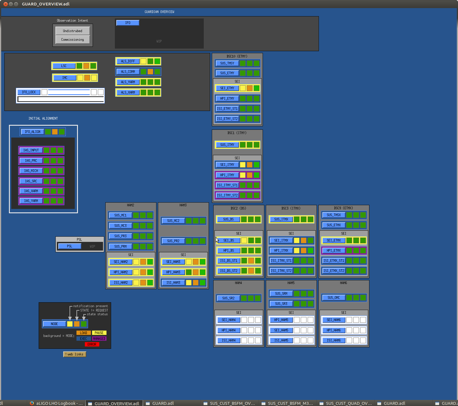
[Arnaud P, Stuart A]

Following closing up chambers, I've created new Guardian nodes for the remaining missing output arm suspensions, SUS_SRM and SUS_OMC, which have been verified to be operating correctly under Guardian control.

Also, Guardian was paused for all suspensions while the chamber close-out work was being carried-out. Since, this is now complete HAM2, HAM3, HAM4, HAM5, HAM6 and X end suspensions have been transitioned to EXEC mode, and Gurdian will be monitoring for any Watchdog trips (see Guardian Overview Status attached below).

n.b. measurements are now underway for ITMX. ITMY, and Beamsplitter over the weekend, so Guardian remains paused for these suspensions for now.
A set of clear Matlab TFs was taken for the top stage of ETMX (QUAD) earlier (see LHO aLOG entry 13134) and lower stage TFs were also taken over the previous evening, which have now been processed as follows:-

- ETMX L1-L1 undamped (2014-08-01_1090929911_H1SUSETMX_L1_damp_OFF_ALL_TFs.pdf)
- ETMX L2-L2 undamped (2014-08-01_1090938935_H1SUSETMX_L2_damp_OFF_ALL_TFs.pdf)

BSC9 ISI Status: ISI damped and ST1 high isolation.

ETMX alignment: No offset was applied during this measurement.

The above TFs have been compared with equivalent measurements from QUADs at similar phases of testing (allquads_2014-08-01_Phase3a_H1ETMX_L*_Doff_ALL_ZOOMED_TFs.pdf), the plot keys are:-

L1-L1
Blue Trace = Model Prediction.
Orange Trace = H1 ETMY L1 (2014−04−12_1081392124), Phase 3a (in-air).
Magenta Trace = H1 ETMX L1 (2014−08−01_1090929911), Phase 3a (in-air).

L2-L2
Blue Trace = Model Prediction.
Orange Trace = L1 ETMX L2 (2014−03−26_0900), Phase 3b (in-vacuum).
Magenta Trace = L1 ETMY L2 (2014−04−23_0900), Phase 3b (in-vacuum).
Cyan Trace = H1 ETMX L2 (2014−08−01_1090938935), Phase 3a (in-air).

Summary:

L1-L1, ETMX measured peaks reasonably agree with modeled peaks, and are consistent with ETMY, with the largest deviation occurring in the 2nd pitch mode.

L2-L2, no measurements have yet been made for ETMY, so comparisons are made to L1 ETMX & L1 ETMY. Again, peaks generally agreement with the model and are consistent with other QUADs.

n.b. there is still a factor of ~2 discrepancy in the DC scaling of the above results, as was also reported by Arnaud (see LHO aLOG entry 13128).

All data, scripts and plots have been committed to the sus svn as of this entry.
Still getting Stage1 actuator trips on the ISI stage1 followed 6 to 8 seconds later by a HEPI actuator trip.
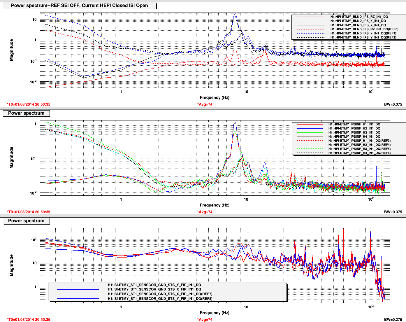
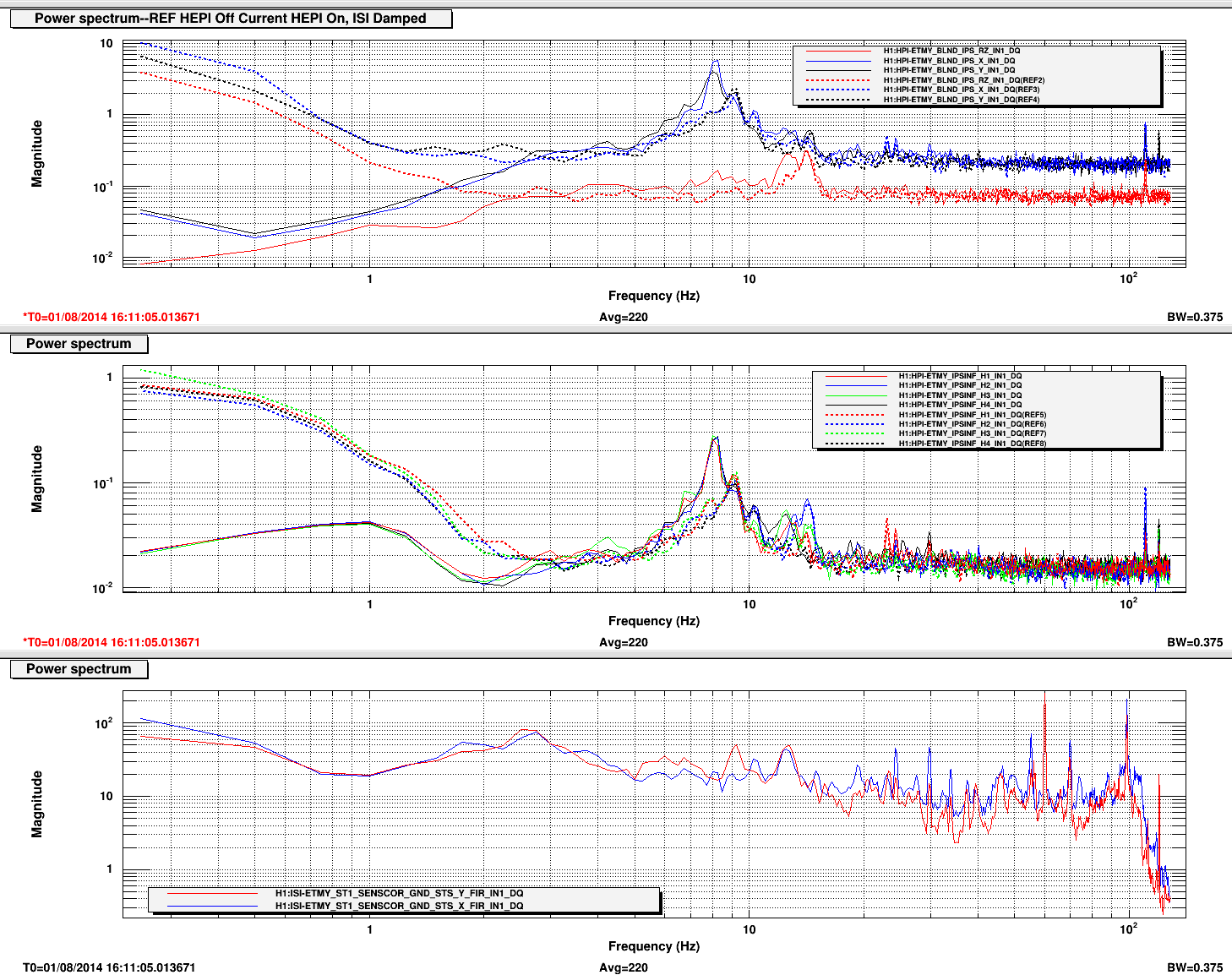
The HEPI will stay closed loop for as long as I'm patient and I've had the ISI in full isolation for periods of time. Sometimes the trips come shortly after the Stage1 of the ISI gets isolated and others it is when the stage2 is isolated. But the trip is always the same--that is: Stage1 Actuator followed byt the HEPI Actuators. These trips have an 8hz signal on them and the horizontal channels are overwhelmingly stronger than the verticals. I've been following spectra and TFs between HEPI & the ISI but can't find the link, yet. There is of course coherence between the HEPI Actuators and the ISI Stage1 sensors & actuators at the 8 hz peak. The radomness may be the dependance on the wandering ground motion... Still hunting
The Attached plot shows the problem peak in the position sensors which comes up with the HEP loops are closed; this seems independent of the ground noise but may be a problem when it wanders into the area.
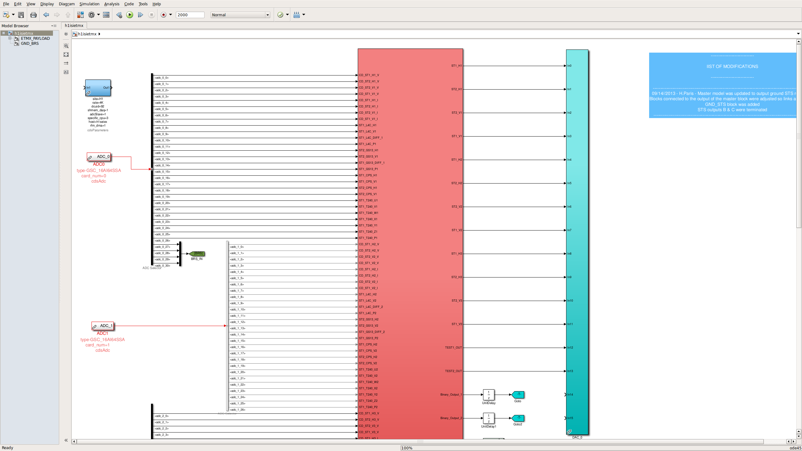
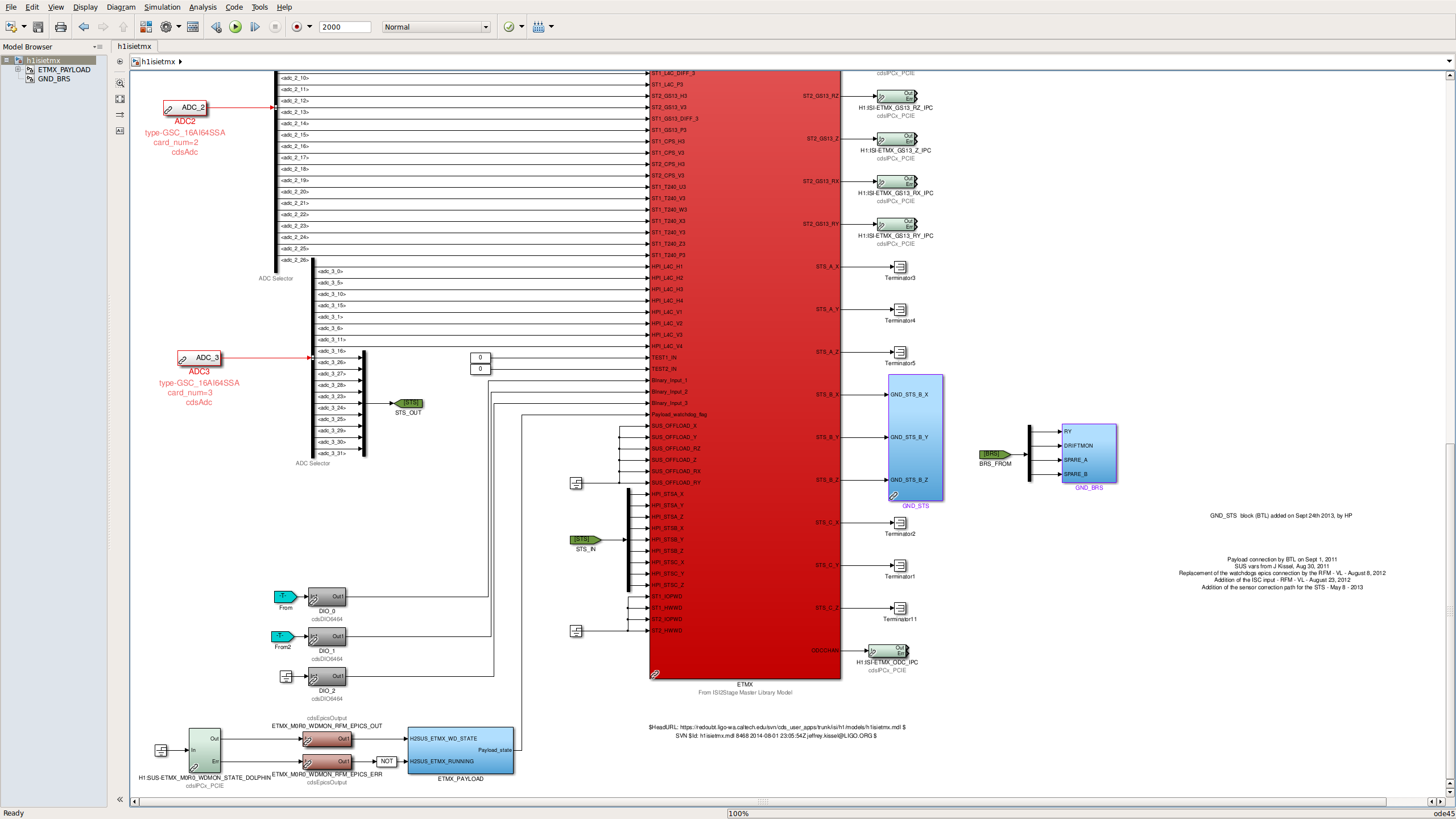
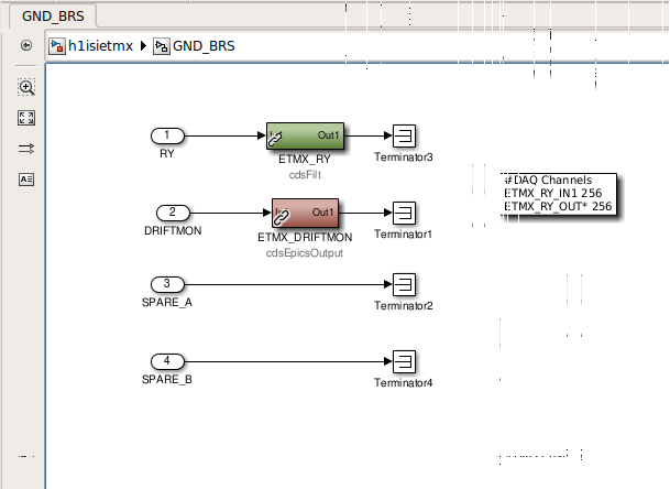
J. Kissel

As per ECR E1400262, and work permit 4764, I've created a new set of channels for the to-be-installed UWash Beam Rotation Sensor (BRS) in the top level of h1isietmx front-end model. This required re-compiling, re-installing, restarting, and restoring the h1isietmx front end process, and a restart of the data concentrator / frame builder / h1dc0 (restarted at 22:48 UTC). Again, because this is all at the top level, not library parts are affected, and I've committed the updated model to the userapps repo.

I've also added two new channels to the frames,
H1:ISI-GND_BRS_ETMX_RY_IN1_DQ
H1:ISI-GND_BRS_ETMX_RY_OUT_DQ
both stored at 256 [Hz], and only the OUT channel (which will be the calibrated channel) in the science frames. More details on the calibration once we get the sensor installed. MEDM screen also to come.

I was able to restore the platform to fully isolated, managed by guardian, before handing over to Jim for over-night measurements.
restarted it at 7:38pm since it crashed after the first power glitch
Particle counts taken during the installation of the BSC1 door.
| Description/Location | 0.3 | 0.5 | 1.0 |
| In cleanroom cover on | 13 | 8 | 1 |
| In chamber cover 1/3 on people insdie chamber | 6 | 4 | 0 |
| In chamber cover on inside work completed | 27 | 11 | 8 |
| In cleanroom door on | 47 | 24 | 11 |
Day's Activities
A clean set of top-to-top TFs were previously taken for the ETMX (QUAD) suspension (see LHO aLOG entry 13134), to complete Phase 3a power spectra have been taken with damping loops both ON and OFF for all stages.

These power spectra measurements have been compared to previous in-vacuum measurements (allquads_2014-08-01_Phase3a_H1ETMX_ALL_Spectra_D*.pdf). The plot key is as follows:-

Black Dashed Line = Expected Sensor Noise
Blue Solid Line = H1SUSETMX 2014−01−28_1600, Phase 3b (in-vacuum)
Green Solid Line = H1SUSETMX 2014−08−01_1400, Phase 3a (in-air)

Summary:

Noise floors for ETMX are consistent with previous measurements. However, the LF and RT channels see features in the V DOF for both chains at ~7.0 Hz, ~15.5 Hz and 26.94 Hz, which were not present in previous measurements. Such features were also seen in recent TMSX power spectra too (see LHO aLOG entry 13151), and could be environmental, due to purge air pumps, clean rooms etc. and should be further investigated to ensure it's not baffle related.

It should also be noted, that the ETMX L2 UL channel exhibits excess sensor noise, as outlined in a recent aLOG entry (see LHO aLOG entry 13065).

All data, scripts and plots have been committed to the sus svn as of this entry.
Particle counts taken during the removal and reinstallation of the north HAM5 door.
| Description/Location | 0.3 | 0.5 | 1.0 |
| In cleanroom while breaking the door bolts | 66 | 28 | 15 |
| In clenaroom with door loose and chamber open | 3 | 1 | 1 |
| In chamber after door off | 30 | 11 | 2 |
| In cleanroom while door being pulled back | 15 | 10 | 0 |
| In chamber after work completed | 12 | 2 | 1 |
| In cleanroom with door installed | 4 | 3 | 2 |
Particle counts taken during the installation of the Y-Arm Spool
| Description/Location | 0.3 | 0.5 | 1.0 |
| In cleanroom before moving spool | 13 | 6 | 0 |
| During moving the spool | 69 | 31 | 6 |
| At spool flange gap - air from inside tube | 35 | 20 | 12 |
| At GV5 flange gap - air from inside tube | 11 | 9 | 5 |
| While closing the sock | 64 | 40 | 12 |
| In cleanroom after install complete | 170 | 107 | 40 |
BSC2
After respraying the BS optic with FC yesterday, we successfully pulled the FC sheets from both HR and AR surfaces of the the BS optic. After N2 blowing and some spot cleaning, we estimate particulate concentrations of 5-10 particles per square inch. We then reinstalled the elliptical baffles which had been removed for FC application, unlocked the SUS, and Jim unlocked the ISI. Quick TFs on the SUS were ran and approved, witness plate situated, and we moved to BSC1.
BSC1
The FC sheet removal from the external surfaces of ITMy went without issue. After N2 blowing, we estimate particulate concentrations of 5-10 particles per square inch on the external surfaces of both optics, and a factor of 2-3 higher on the internal surfaces. We unlocked both chains, Jim unlocked the ISI, quick TFs on the SUS ran and approved, witness plate and 1" optic installed, Betsy wiped her way out of chamber, and we handed it over to Apollo for door installation.
Particle count measurements were taken in BSC 1 and 2 numerous times during the ~2 hours of First Contact removal and chamber closeout on Friday. First Contact was pulled on the BS HR and AR surfaces around 12:30pm. FC was pulled on the ITMy HR, CP-AR around 1:45pm. BSC1 door was attached to chamber around 2:30.
Counts were always around:
0.3um ~200
0.5um ~60
Gerardo, JeffB, Mike, Hugh, Travis, Appollo, Kiwamu,
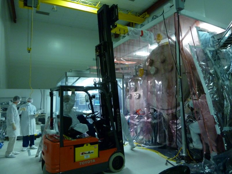
We have removed two irises from the output faraday isolator (OFI). They were originally meant for a temporary tool for aligning the OFI and we simply forgot to remove them. So we opened up the HAM5 north door and locked the north side of the ISI. Then we took out the two irises -- one at the input side and the other at the output side. Note that we left the irises' holders attached. Also, Gerardo replaced the holder at the output side with a clean one because the one we had was not class-A compatible.
After unlocking the ISI, Hugh checked the balance of the ISI and he did not see a significant change. So we did not have to put a counter weight as expected.
We revisited the HMA5 installation exit check list, performed those activities and found nothing special. So it is good.
Some pictures will be uploaded later.
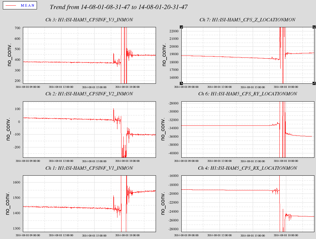
Here is 12 hours of the Vertical CPS channels. The left three are the local in counts and the right three are Cartesian in n(m/rad) Nice that we can so clearly see a 22 gram payload change. In the local basis we have +-1600 lock unlock shift spec as being balanced close enough. When I balanced this on 21 July , the shifts were <200cts. So the comparison seen before and after the disturbance when JeffB half locked the ISI and ISC removed the irises are still well within our spec. The signs and magnitudes all make sense (Thanks ISC for this check!) with the worst being RX tilting 6urads.
This plot is interesting. It seems the only moderately pronounced peak in the horizontal ground spectrum wanders, seen from 8 to 11hz changing quite rapidly.
The attached plot's current traces are with HEPI loops closed and the ISI Damped. While the middle graph shows all four local IPSs have the strong 8hz peak (the dashed REFs are with the HEPI loops open), the peak only shows in the X & Y and not the RZ cartesian traces (top graph). Also, note the bottom graph where the ground sensor pretty much has nothing at 8hz but does have a minor peak just above 9hz that is also peaking up in the local sensors.
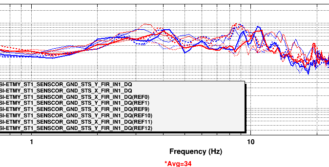
The second plot shows just the ground Seismometer with X & Y traces from last night (Dashed) and the others from this morning. The peaks in that area come and go and wander around so it may or may not be a problem or just a red herring (are those edible?)
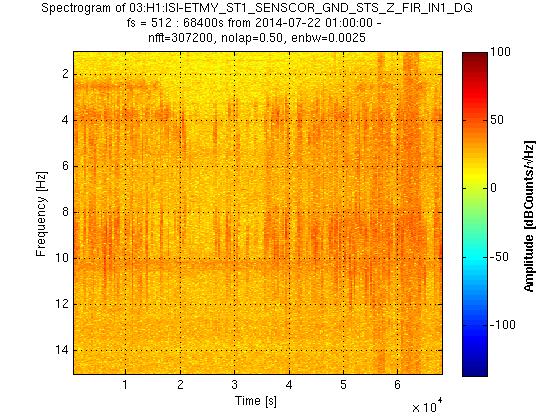
I am attaching the spectrograms for the X, Y, and Z directions of the STS Seismometer in ETMY.
I used 19 continuing hours, starting 2014-07-22 01:00:00 UTC.

There is a feature that is present all the 19 hours:
Around 10.5 Hz  in X direction.
Around 9 Hz in Y direction.
Around 10.5 Hz in Z direction.

More features can be seen wandering along the 19 hours around 3-5 Hz and 8-10 Hz, for X, Y, and Z directions.

In the spectrograms, each count is 1 nm/s /sqrt(Hz).
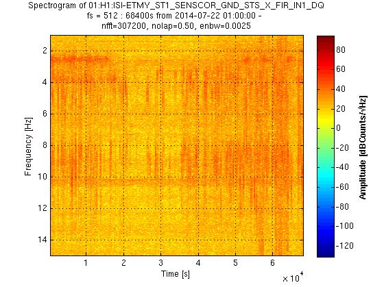
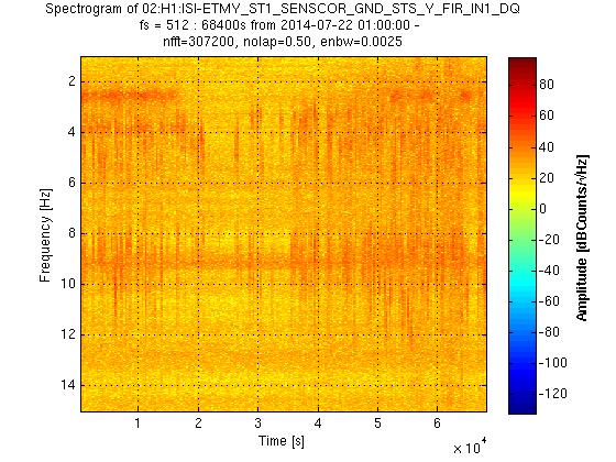
Continuing with the investigation on the 8 Hz, I am attaching the spectrograms for the X, Y, and Z directions of the GND STS in EY.

Comments on the spectrograms:
- Feature wanders between 7.5 to 12.5 Hz.
- Depends on the time of the day.
- It is present every 15 to 30 minutes.
- Displacement amplitude higher than 2 nm.

6 hrs were used for each spectrogram, starting:
- August 01, 2014 00:00:00 UTC (Figure 1)
- August 01, 2014 06:00:00 UTC (Figure 2)
The 8 hz motion seen here is most likely related to the "pier resonance"
Laura Nutall has a nice set of plots in the DCC https://dcc.ligo.org//LIGO-G1400820
which show this motion.
Likely you are seeing the floor component of this motion. Rich M. has data showing that (at MIT) the slab bending is an important component of this motion
I investigated the GND SDS and PEM MIC channels using the coherence tool at 100mHz bandwidth and found several peaks between 5 and 9 Hz. I've attached some slides with zoomed-in plots.
ITMy
CPy
*** This is the actual pitch of the CPy. The listed error is relative to where the CPy needs to be to be parallel with the ITMy AR surface, assuming the ITMy has zero pitch error; this does not include any FC correction done on the ITMy. Since we cannot verify the ITMy pitch after FC removal, we also cannot verify the CPy pitch relative to the ITMy AR surface after FC removal. We have to assume that E1200791 is correct (we have only been able to test this one time at the ETMy, which moved upward by 442 µrad, but one data point does not a trend make) and that the ITMy will pitch up by ~352 µrad upon FC removal. Therefore our expected relative pitch between ITMy and CPy upon FC removal is 490 µrad up (14 µrad down ITMy HR pitch + 1309 µrad down wedge - 833 µrad CPy pitch = 490 µrad up relative pitch). As stated above we can weigh the FC to get some idea of the pitch change.
ACB (relative to the ITMy)
This completes IAS alignment of ITMy; our equipment has been removed from the Y manifold spool area to allow for the Cryopump Baffle installation. This also ends the IAS alignment of the aLIGO H1 interferometer.
First off, small correction to the ITMy target pitch: it should be 339 µrad, not the 340 µrad as listed. This puts the ITMy pitch error at the time of IAS equipment teardown at 27 µrad down.
Measured the mass of the First Contact removed from ITMy today.
 Unfortunately the mass of the FC came in under the expected mass and below the allowed variation; if you look at E1200791 the allowed variation of the FC mass is 0.159 g, which results in a low end mass expectation of 2.955 g, not the 2.8 g I measured.