Gary T, Danny S, Stuart A, Matt H, Mark L (Apollo)
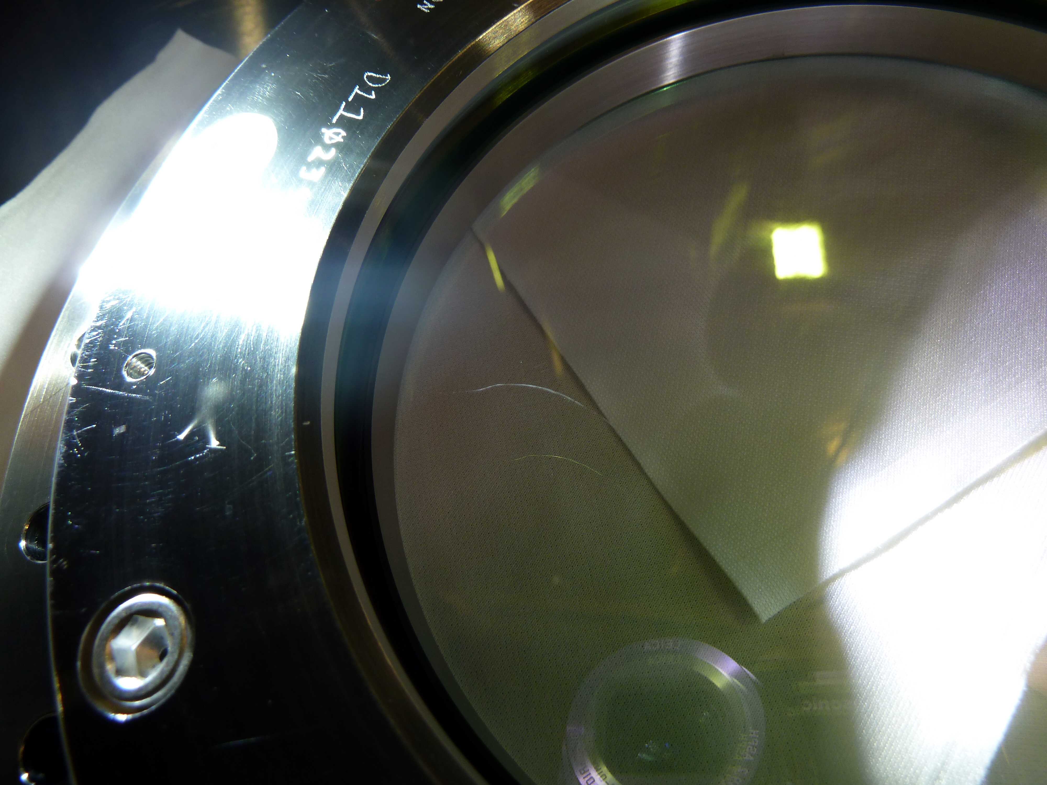
The closeup of the X-end (BSC9) is complete. Stuart has a detailed log of the timeline of the steps we did everything that he will post to this alog which gives various info on how long things took, particulates on optic, etc.
Before heading down a round table discussion (including Mike L, Norna, Calum T, Rich A, Gary T, Matt H, Danny S) looked at the information regarding the deionisation tests done at LHO and CIT and what we should do going forward in terms of using the top gun for pulling first contact. The decision was to blow between the gap of the two optics first for a smal lperiod of time (with FC still on ERM and HR of main opitc) to dislodge any large debris. Then starting with the ERM first contact, take around 2 minutes to peel this FC (blowing with top gun at the same time). Then on top of that (and starting with the ERM surface), for 1 minute blow on the ERM surface, then for a minute blow between the two optics, then back on ERM surface for another minute....and do this 9 times (for a total of 9 minutes) ending on the ERM. Thenn move to the HR of main optic. Take ~2min topeel FC here..blowing with top gun the whole time, then again starting with the HR surface, blow on this for a minute, then between the gap of the optic for a minute, then back on the HR surface for a minute (again 9 times...for a total of 9 minutes), ending on the HR surface.
So with this in mind, we headed to the end.
The Quad was locked
Wafers added to Quad
FC pulled on witness optic
FC pulled on ERM
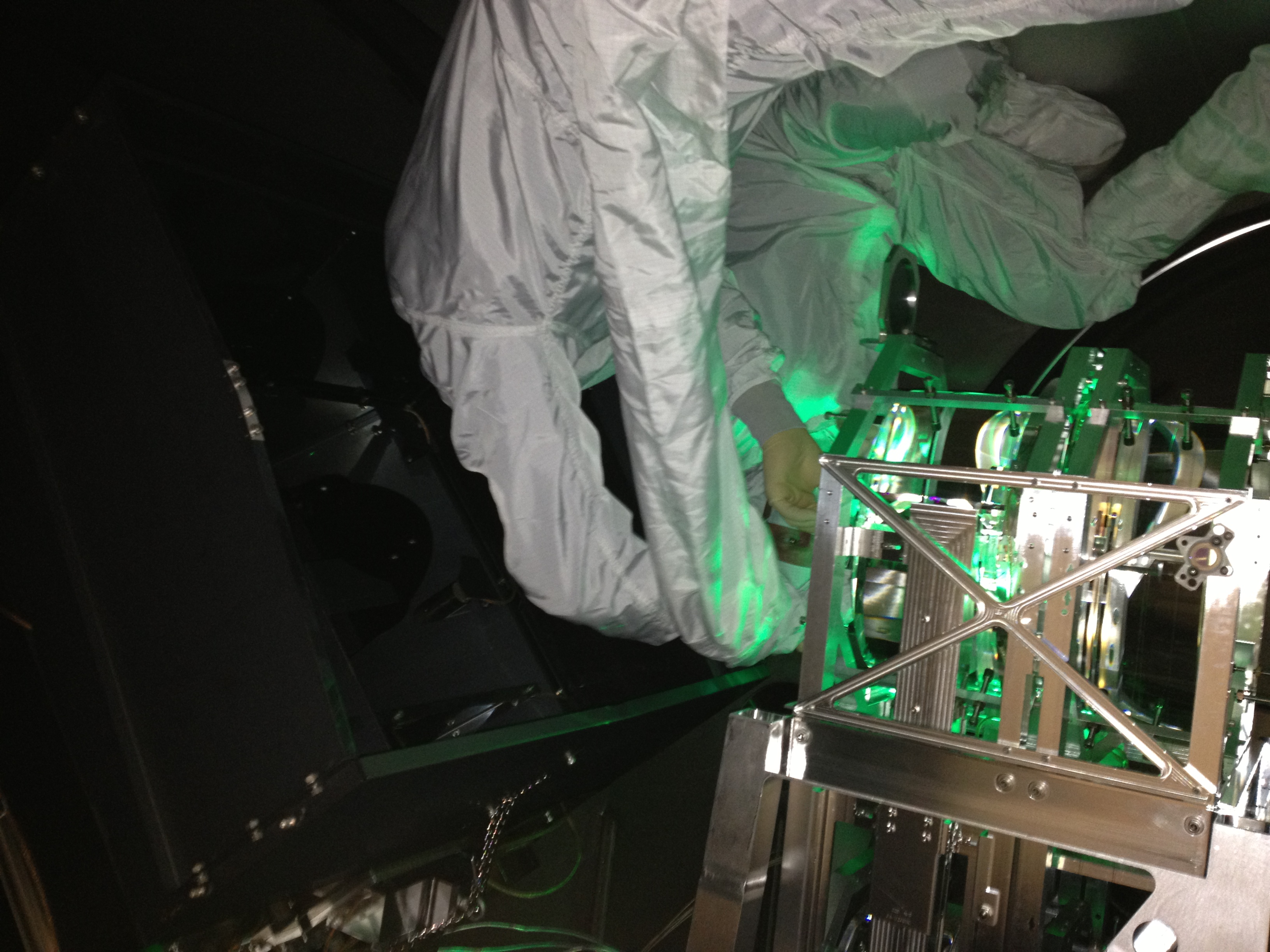
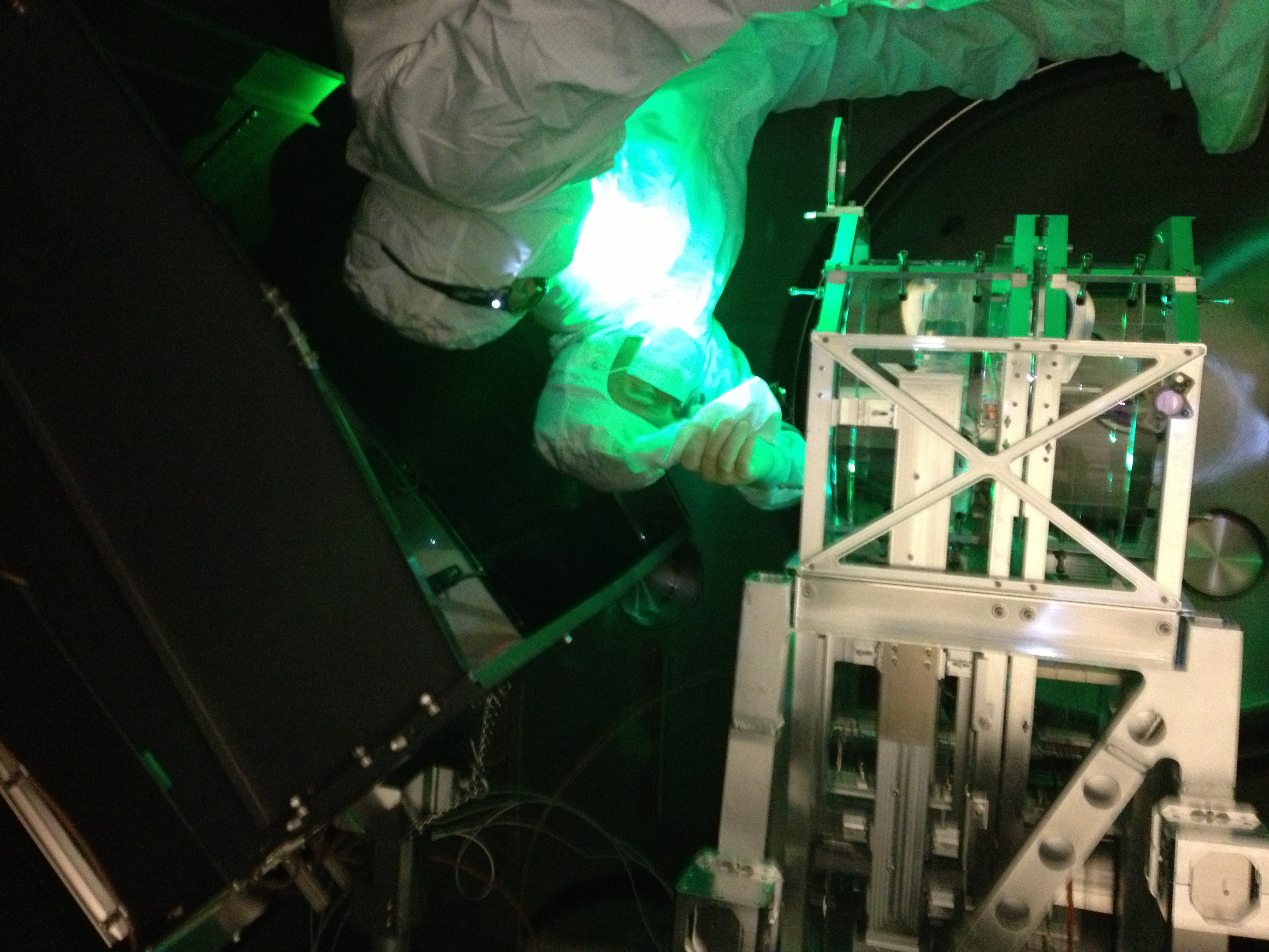
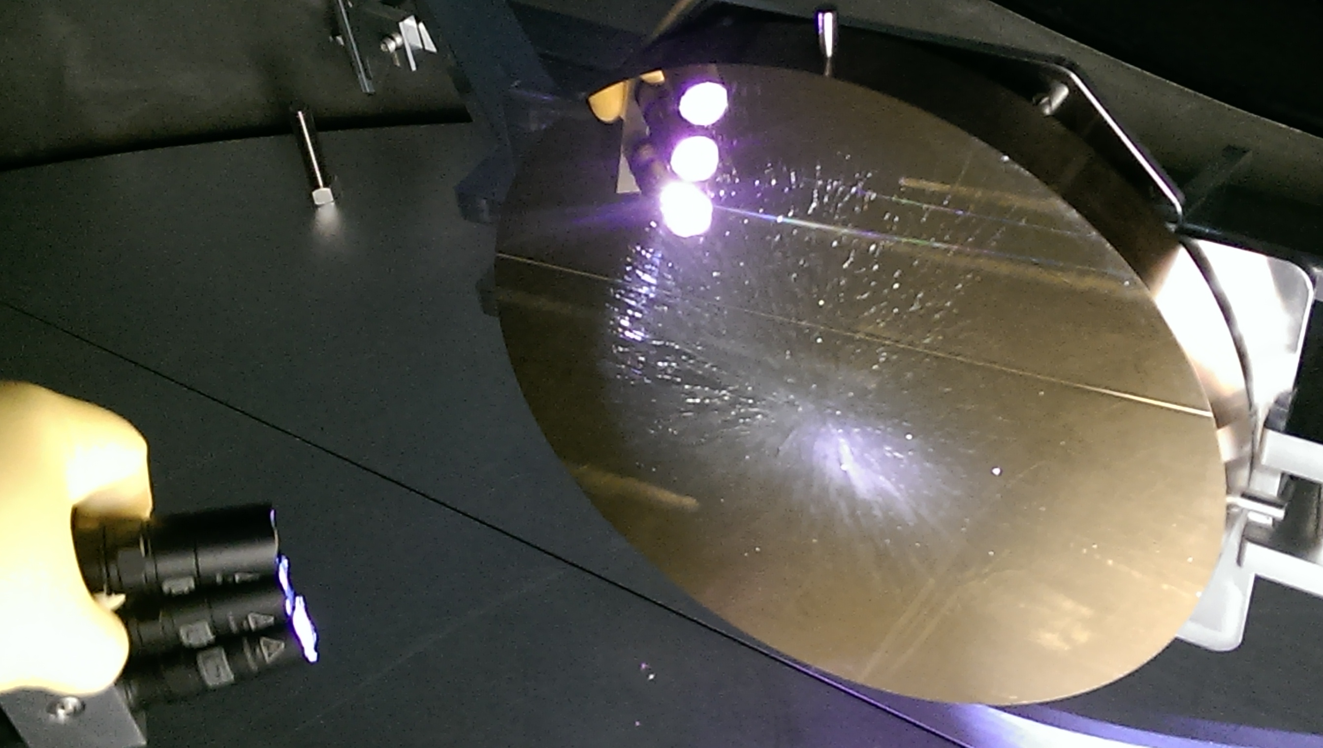
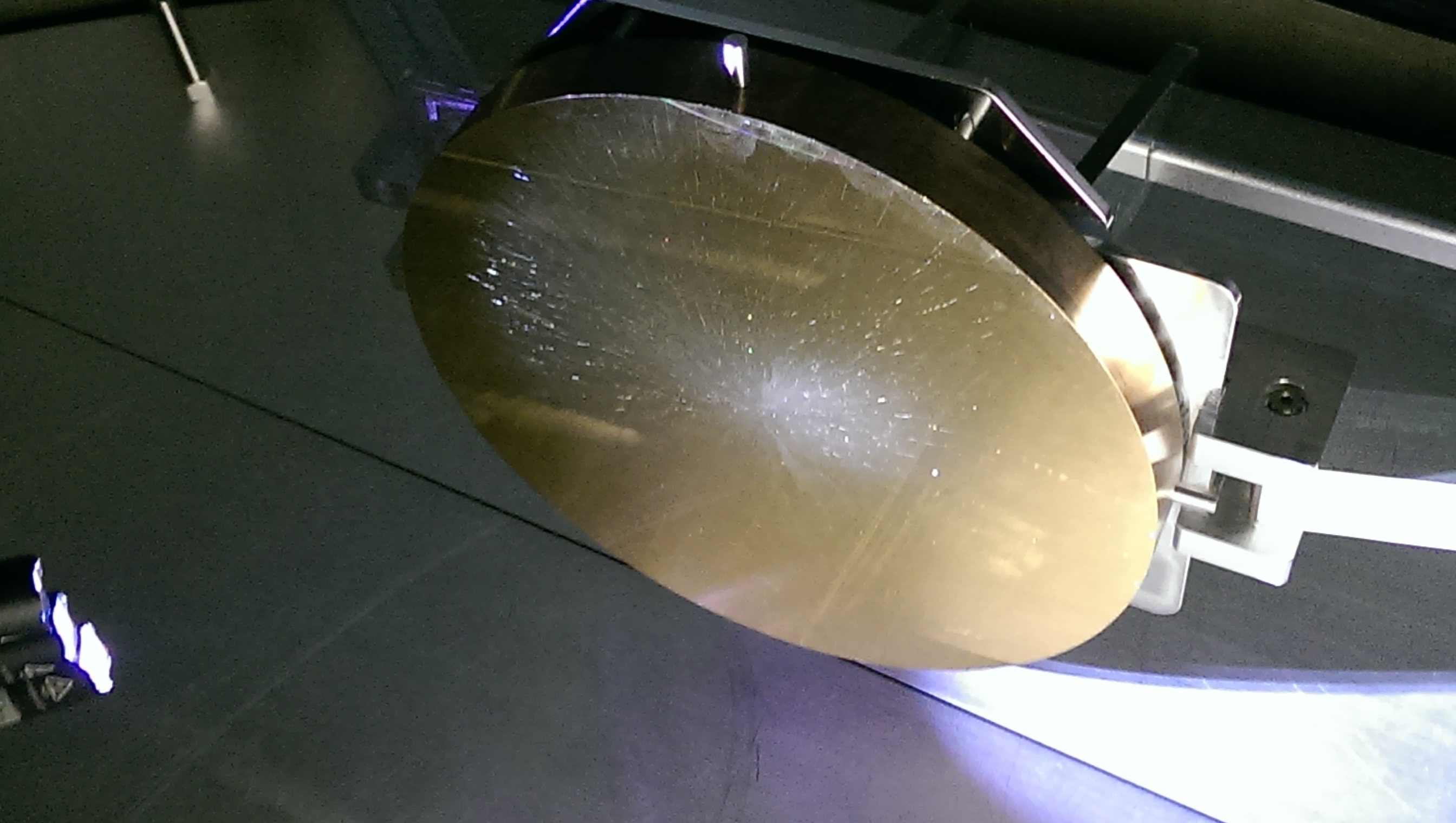
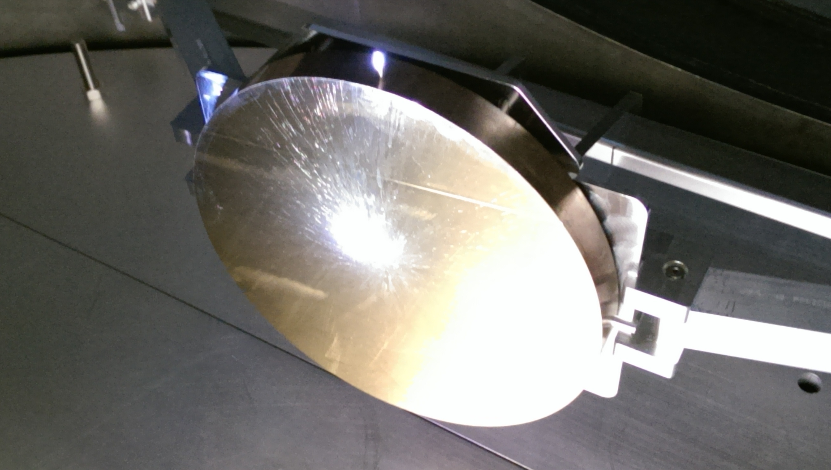
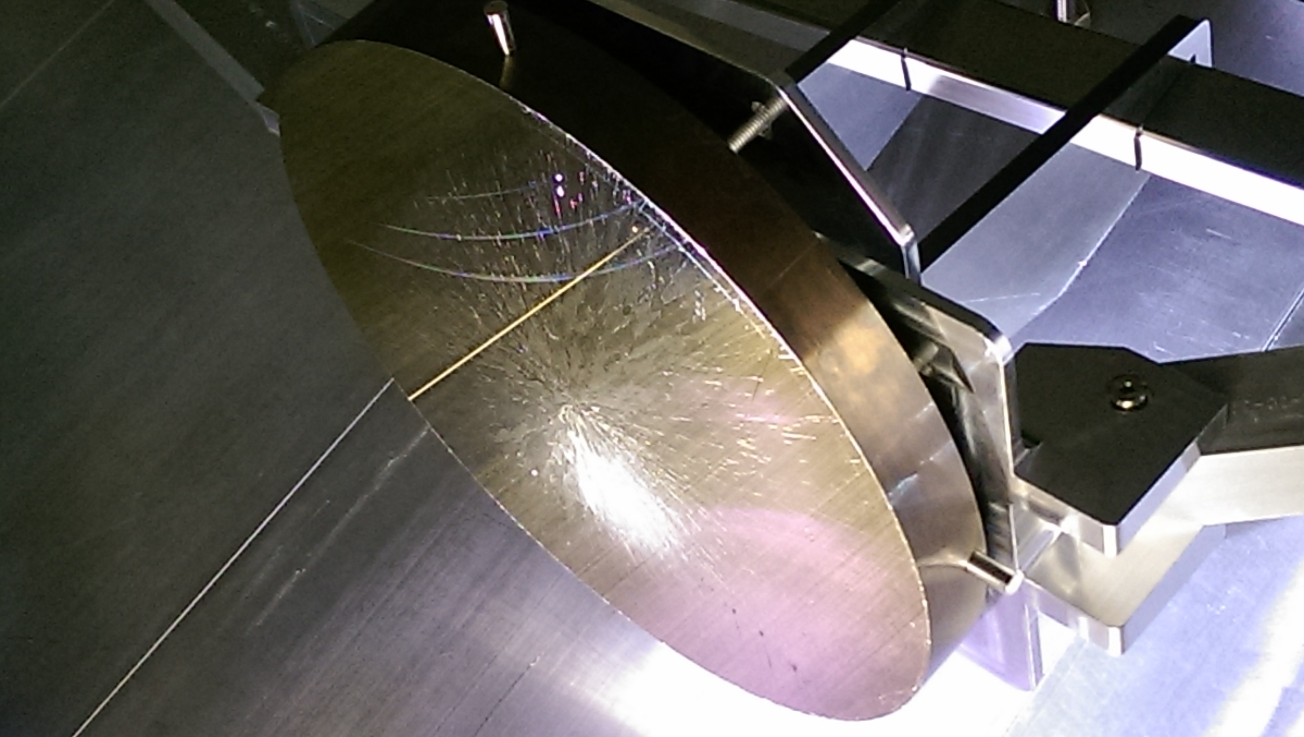
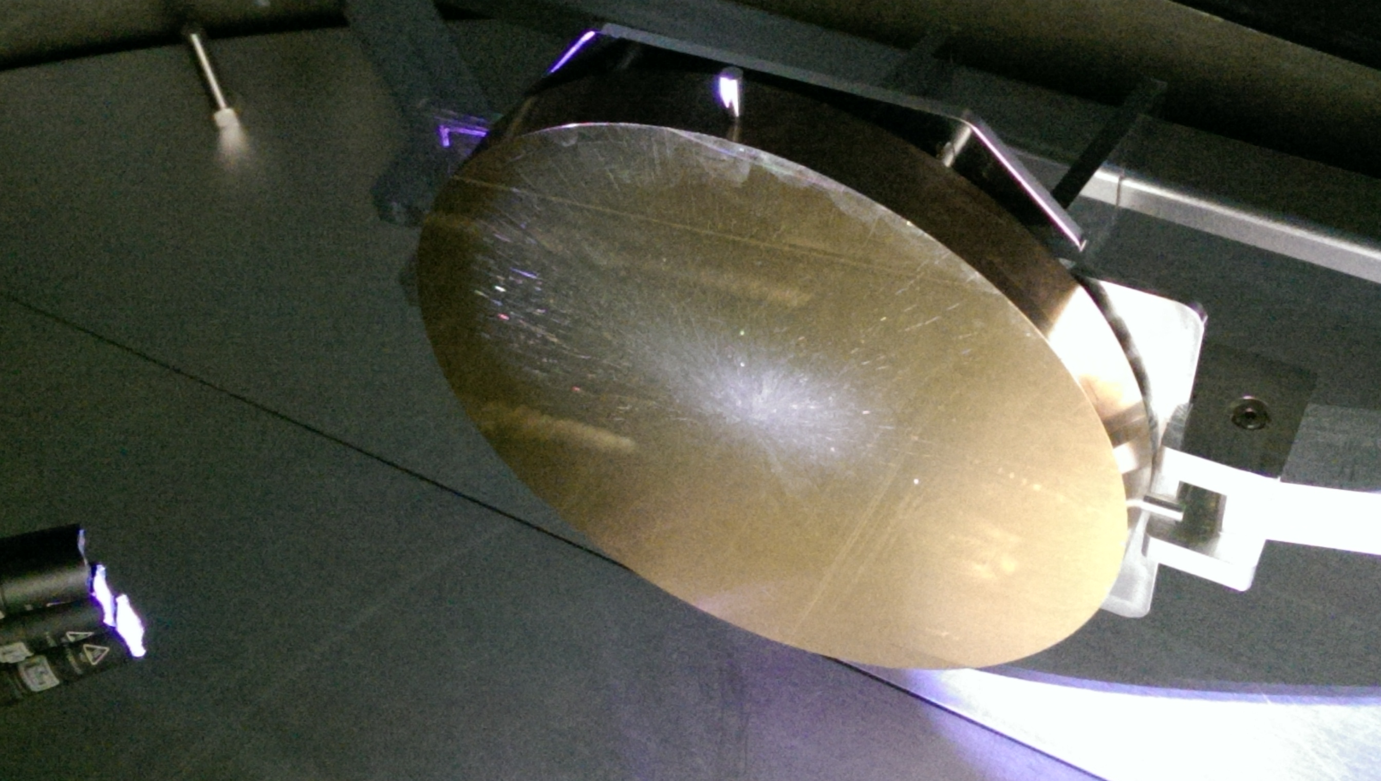
Inspection of ERM surface with green light
FC pulled on HR surface main optic.
Inspection of HR surface with green light
Swung arm cavity back down
Unlocked Quad and ser EQ stops
Centered some OSEMs (BOSEMs on main and reaction chain and aOSEMs on L1 stage)
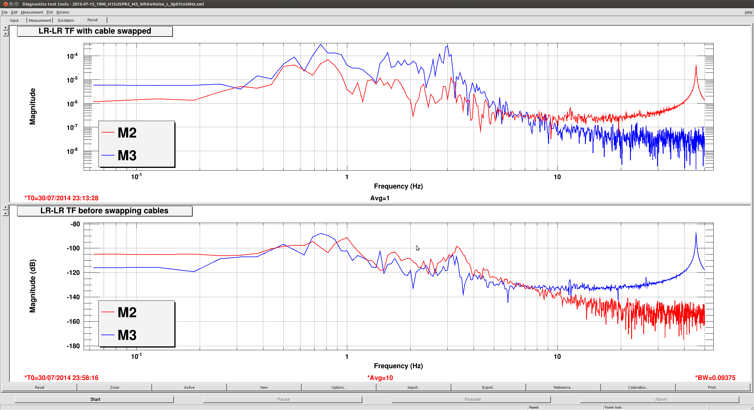
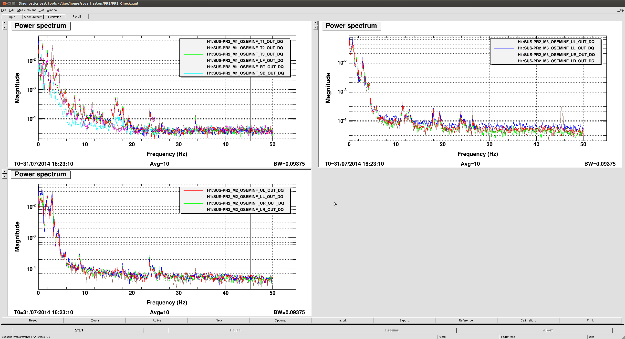
Ran quick TF's on Quad main and reaction chain to see if free
Door went on
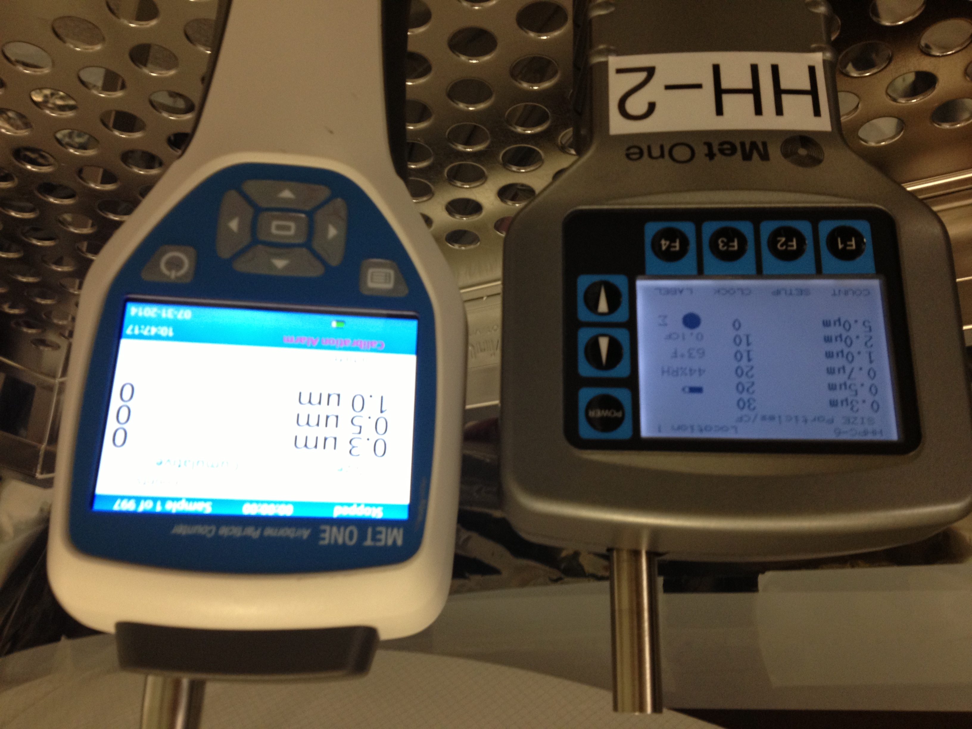
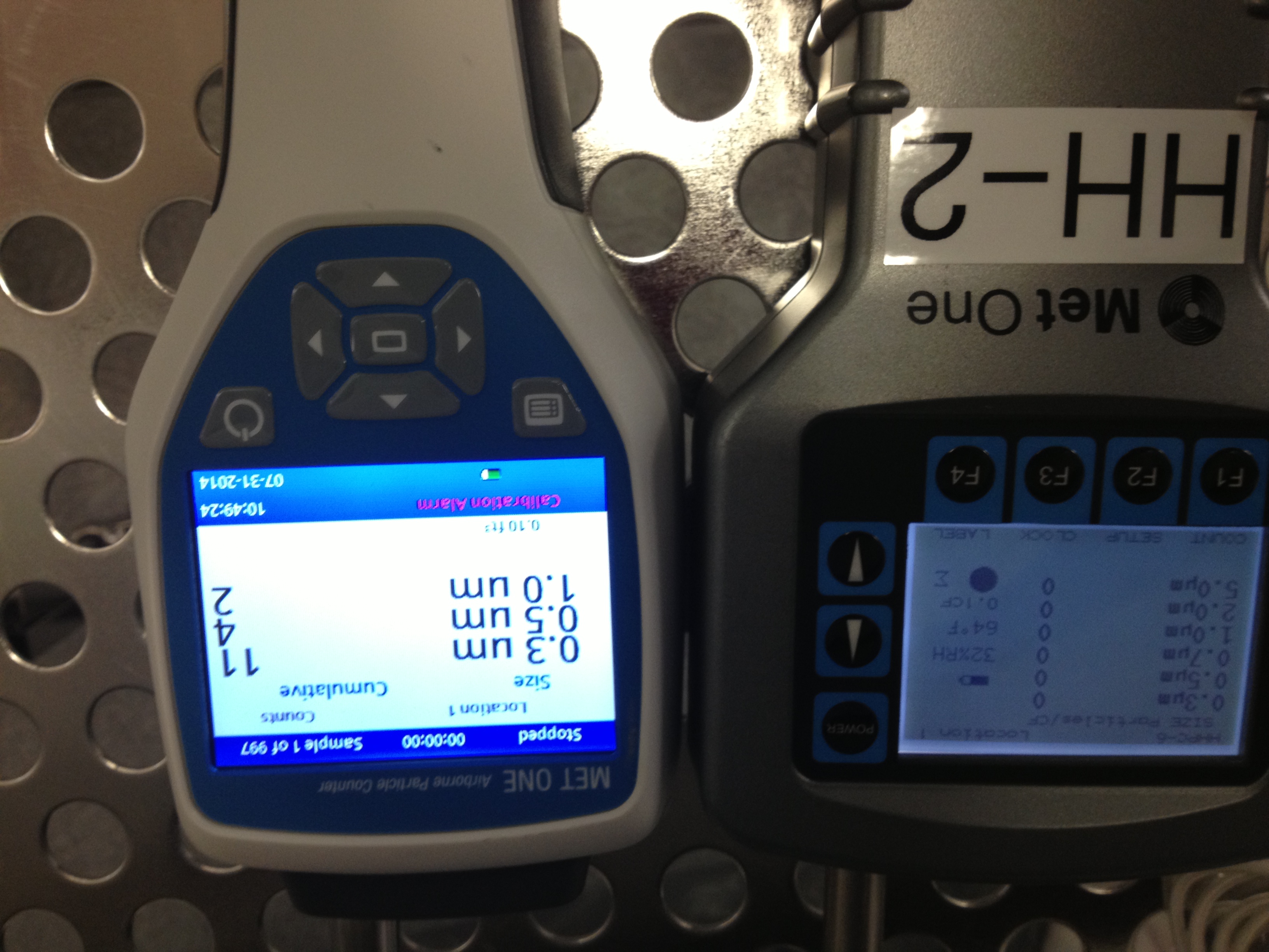
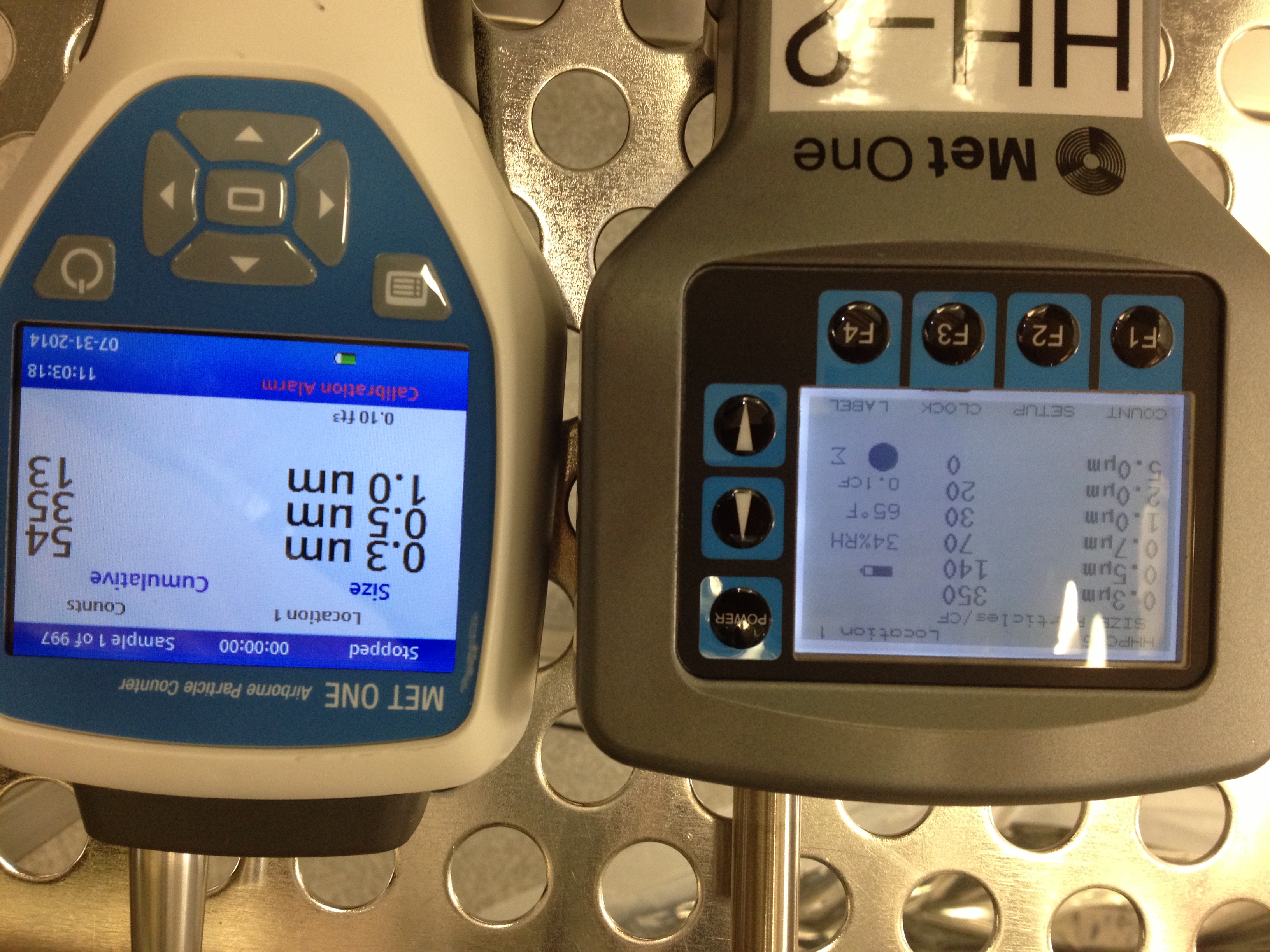
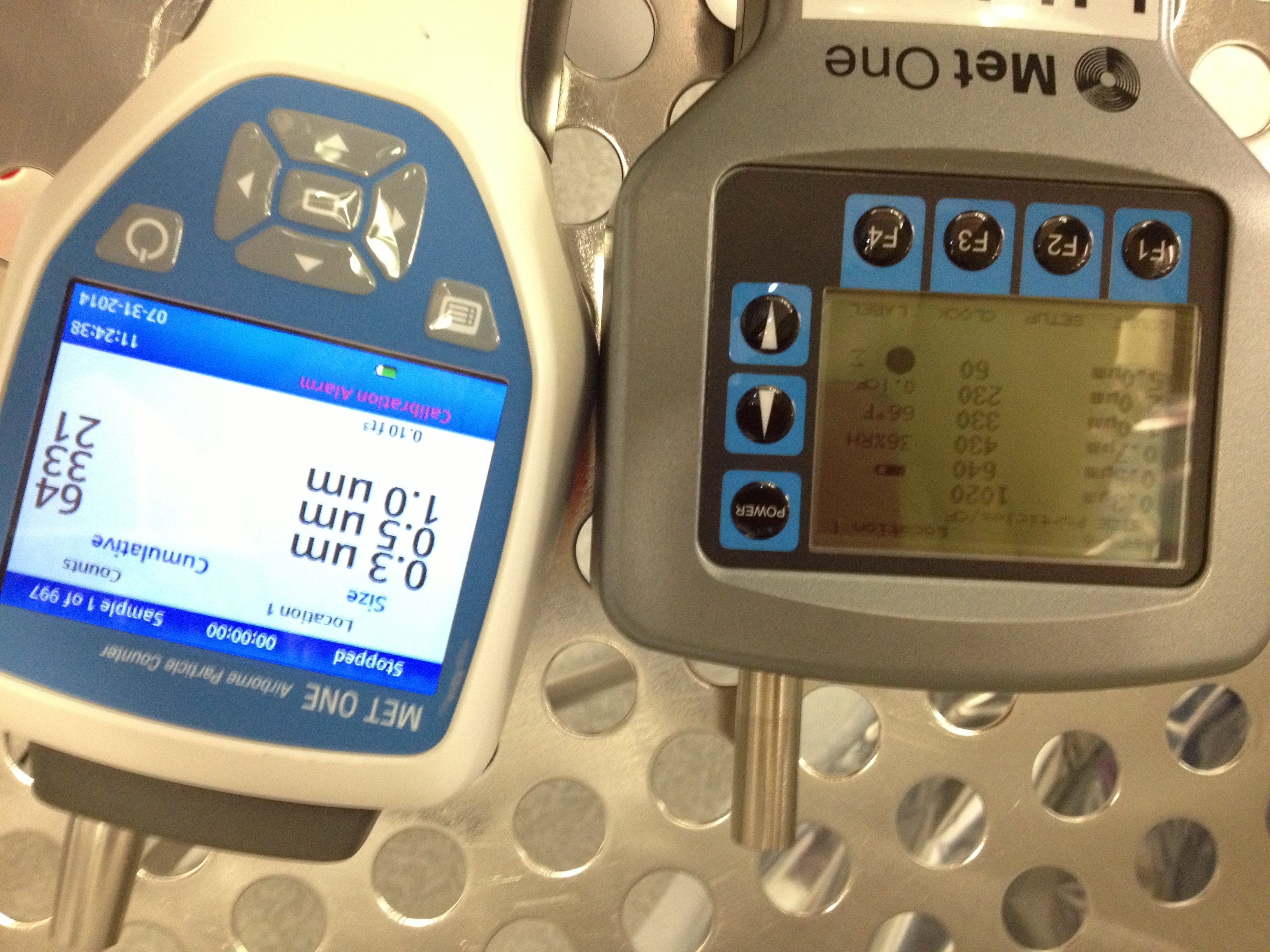
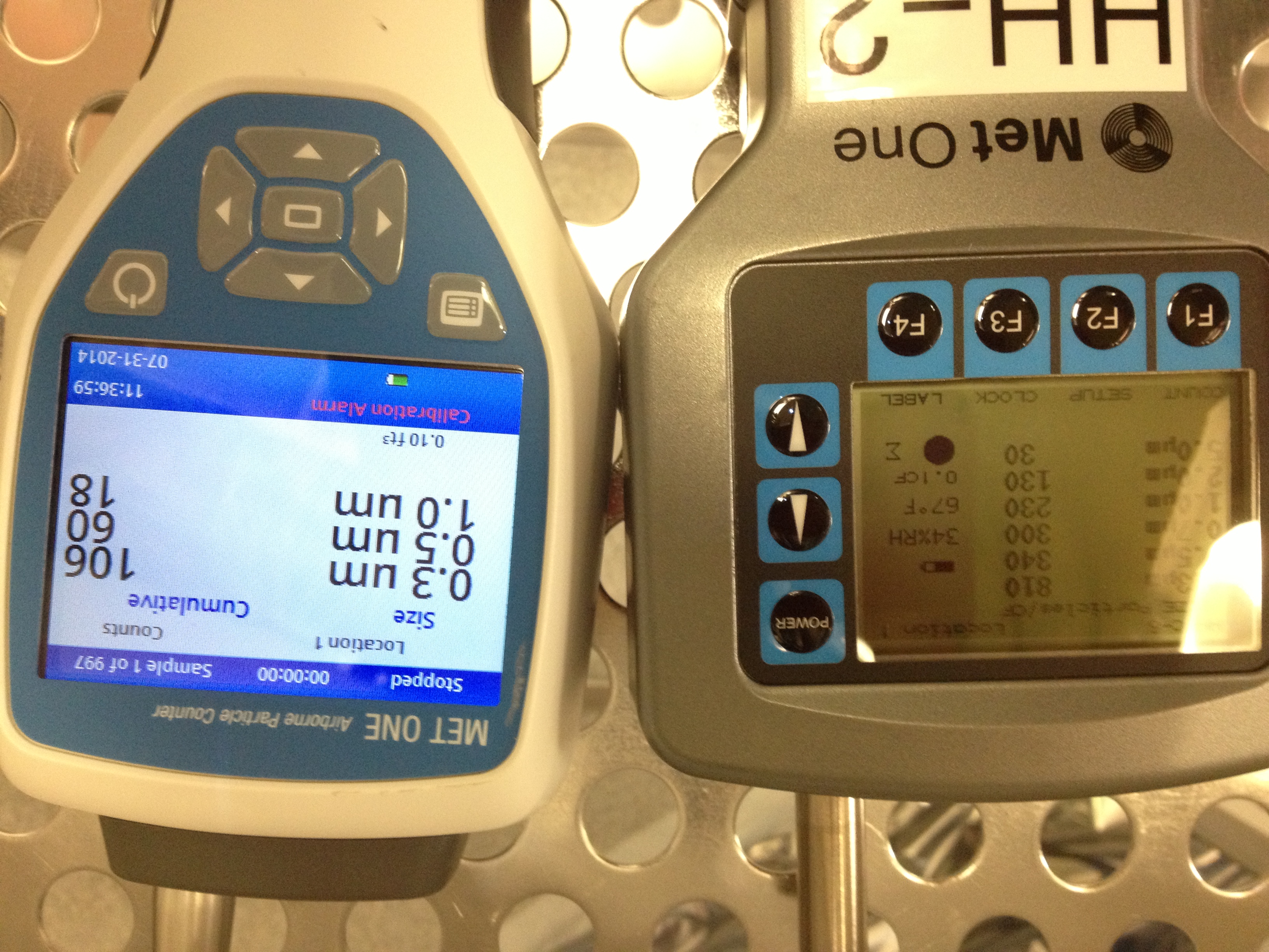
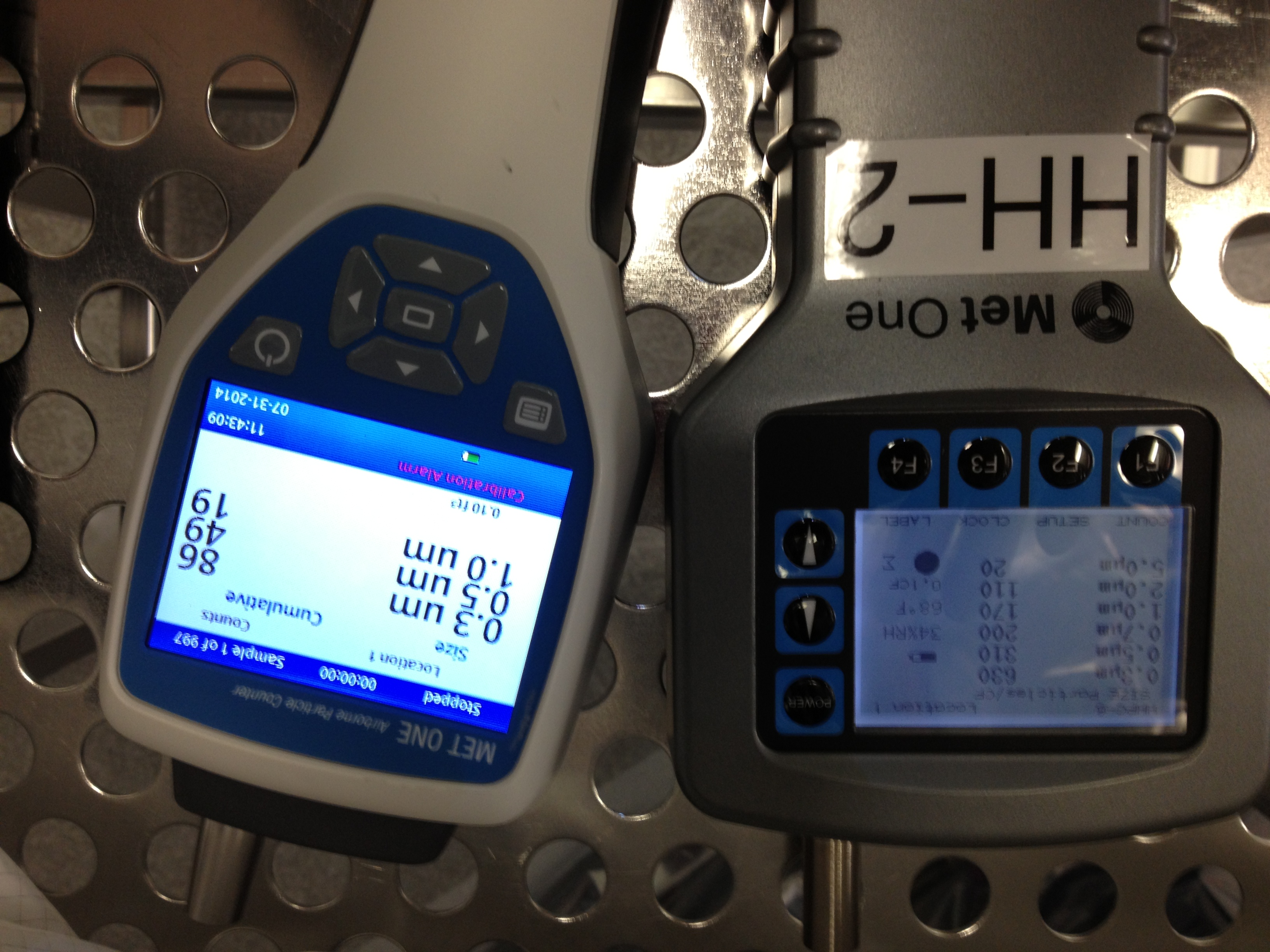
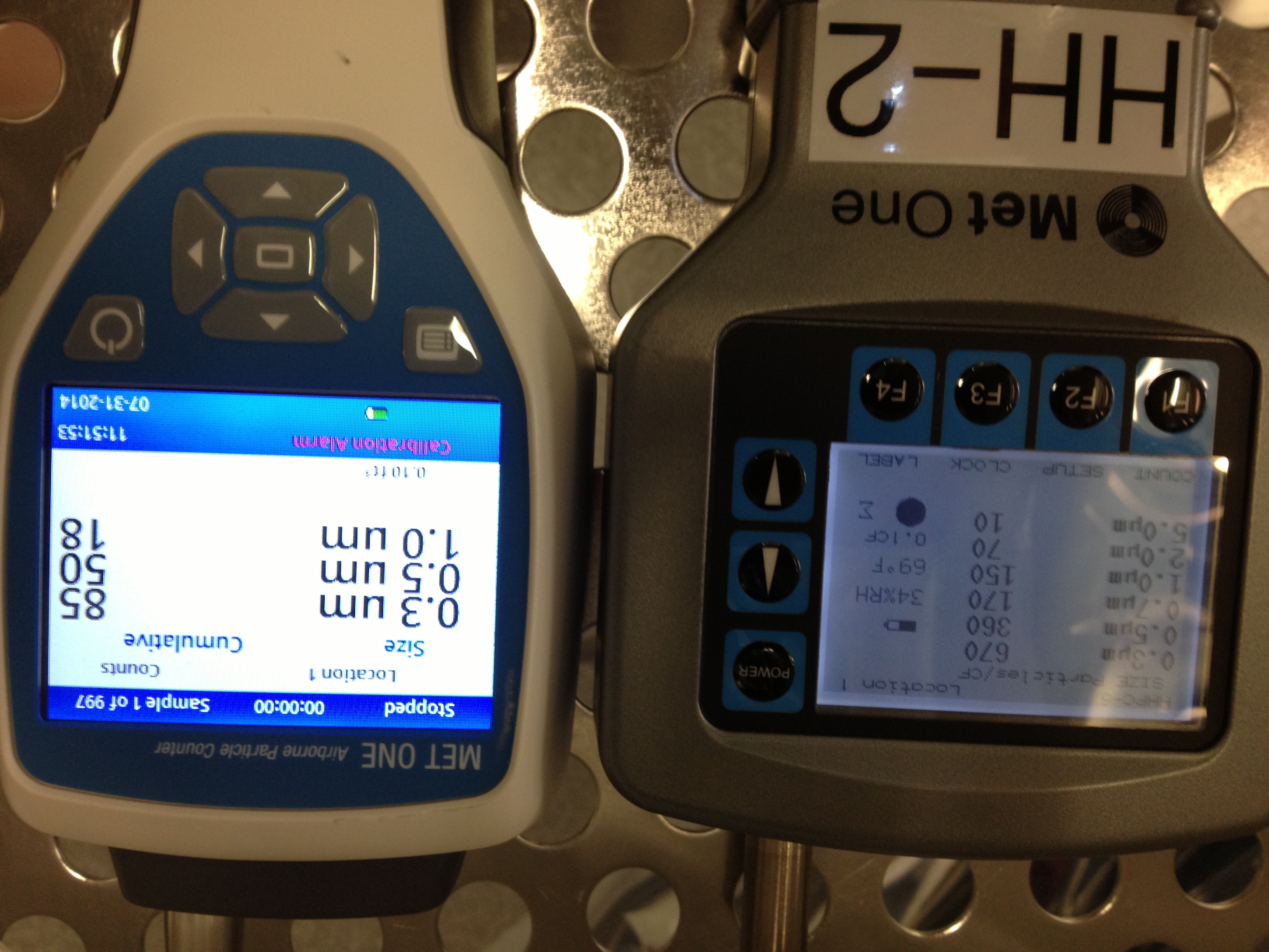
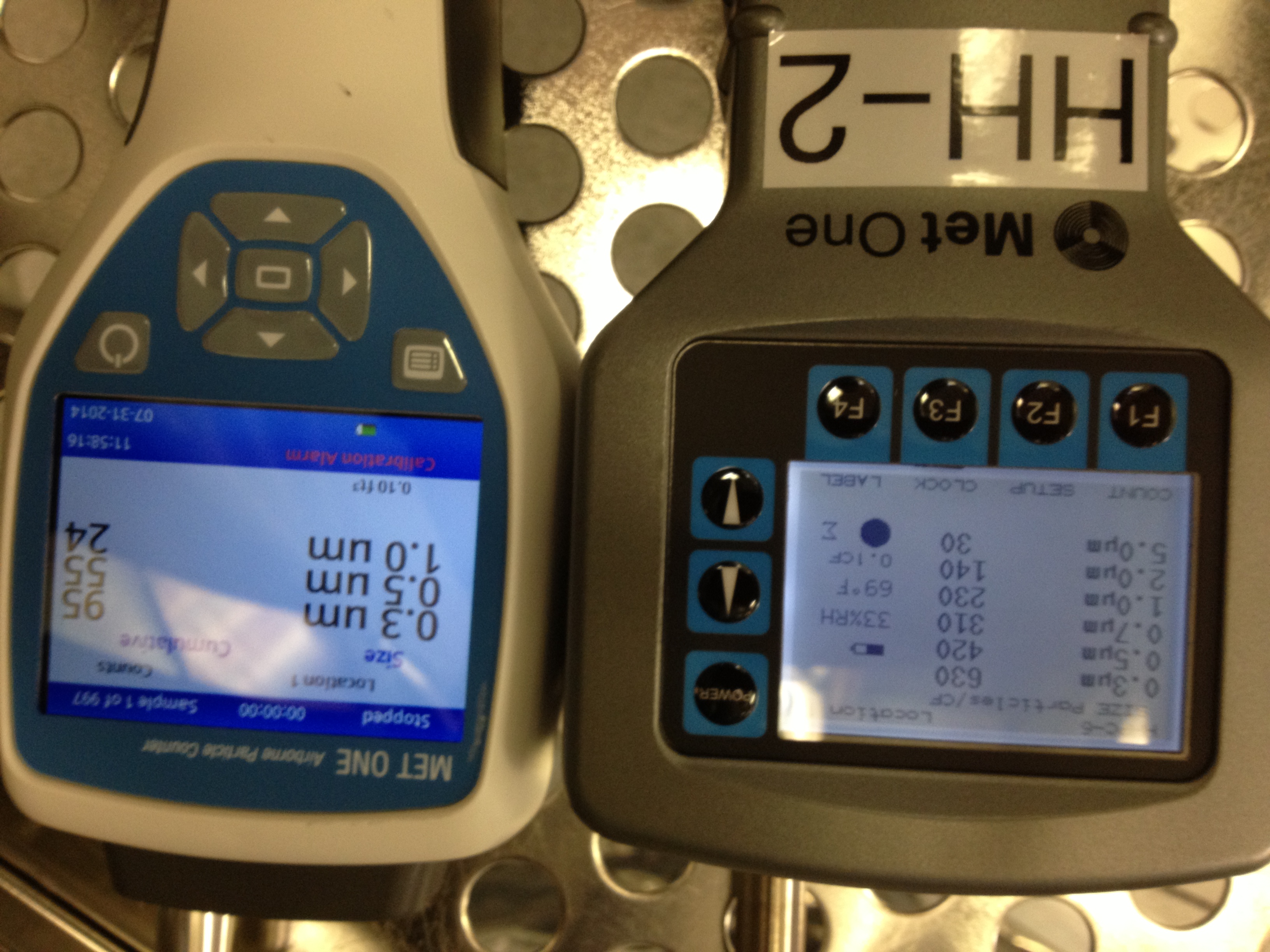
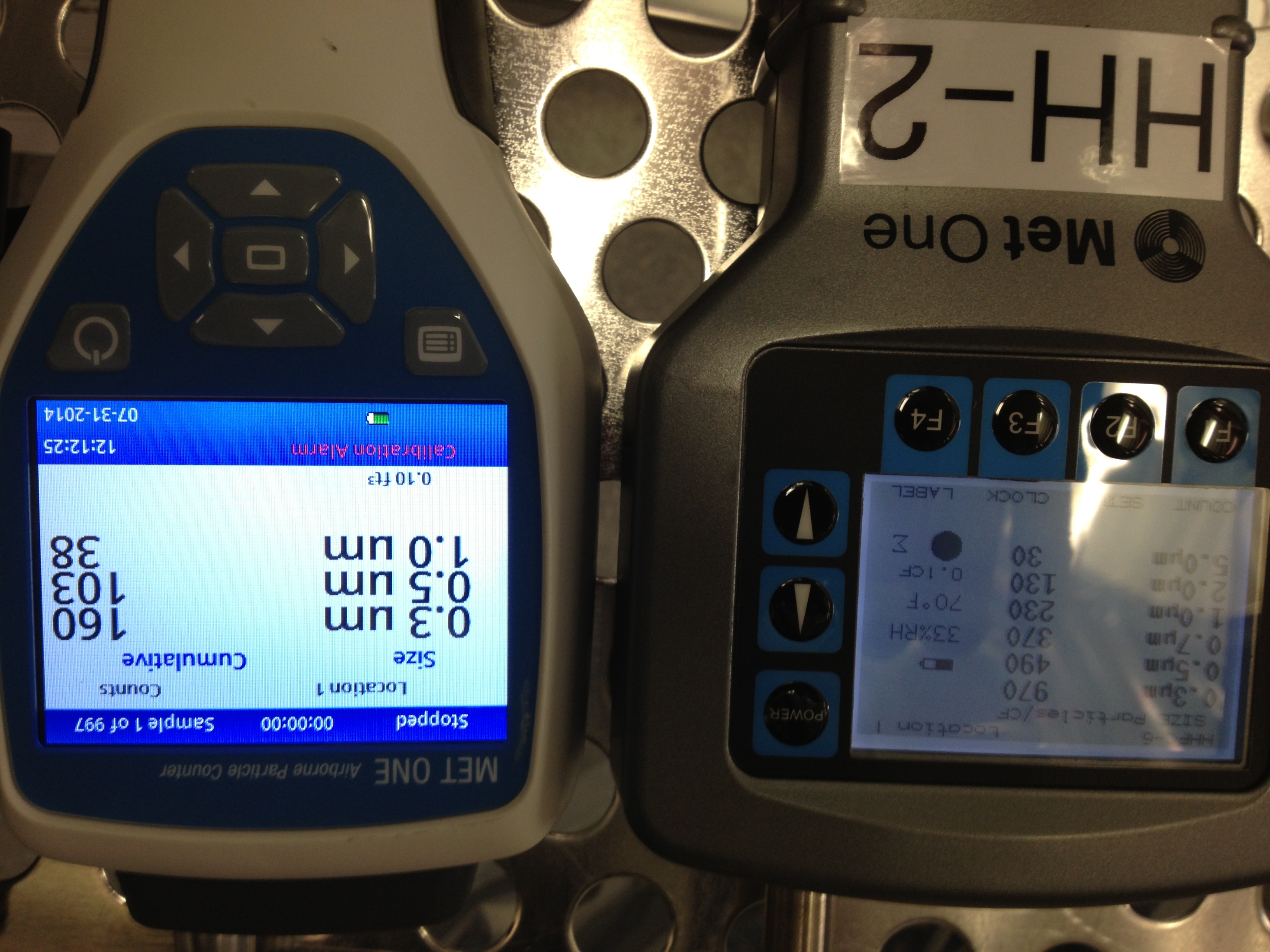
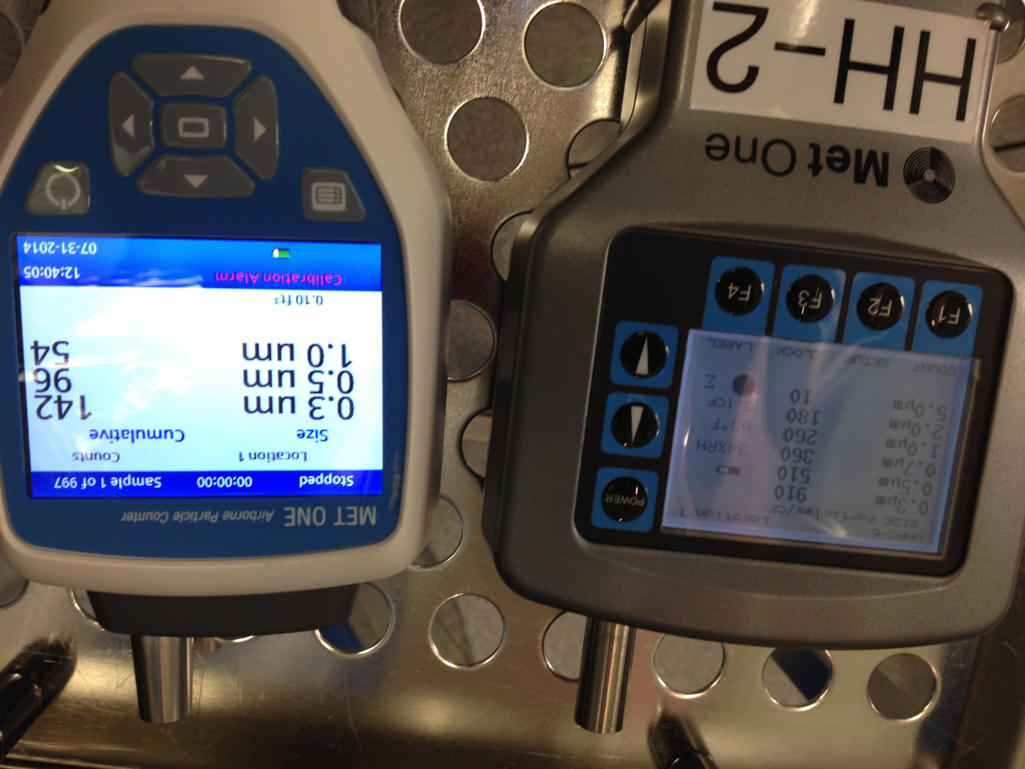
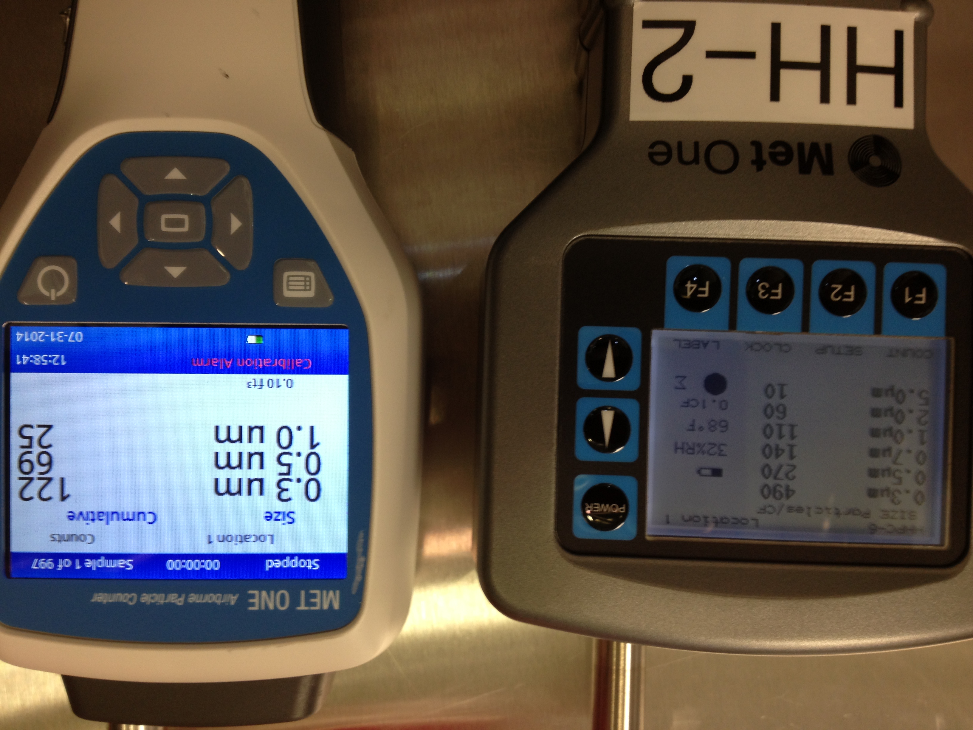
Below are the particle counts taken during the closeout of the chamber. To interpret when during the closeout these were taken look at Stuarts timeline and look at the 0.3um particle size counts reading that he lists. Then look at the pics and look at the grey Met one counter that gives same particle counts as is listed in timeline. I have taken side by side counts using two different particle counters at the same time, same place, same duration (and I believe same settings), showing how we get different results.
Also the firt two photos show the In cleanroom and then initial in chamber particle counts (thats not in Stuarts timeline)
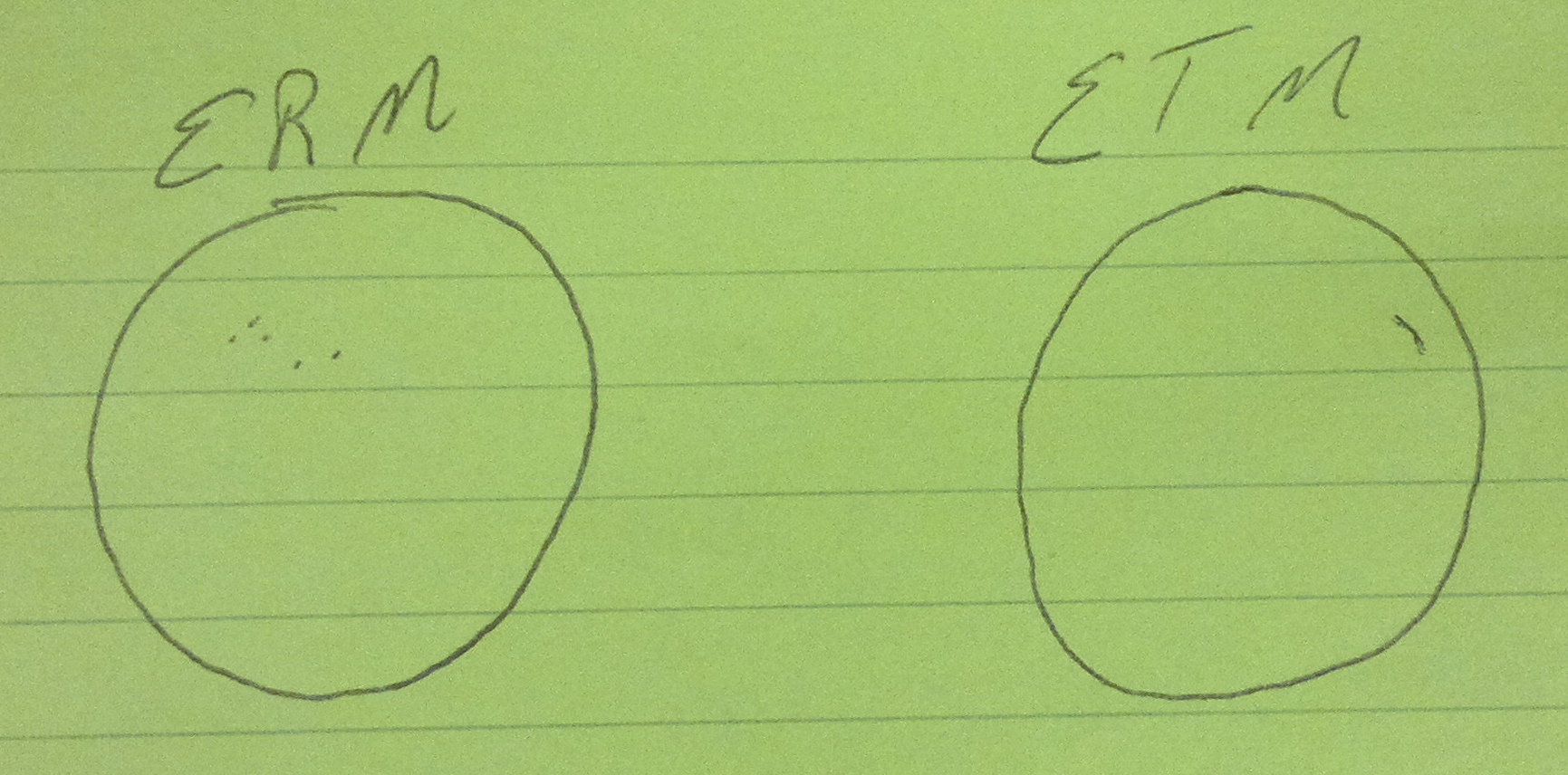
Attached below is a log and particle counts taken during the BSC9 close-out work covering the period 1055 (local) to 1315 (local), as well as Danny's drawing of the first contact residue on each optic.


