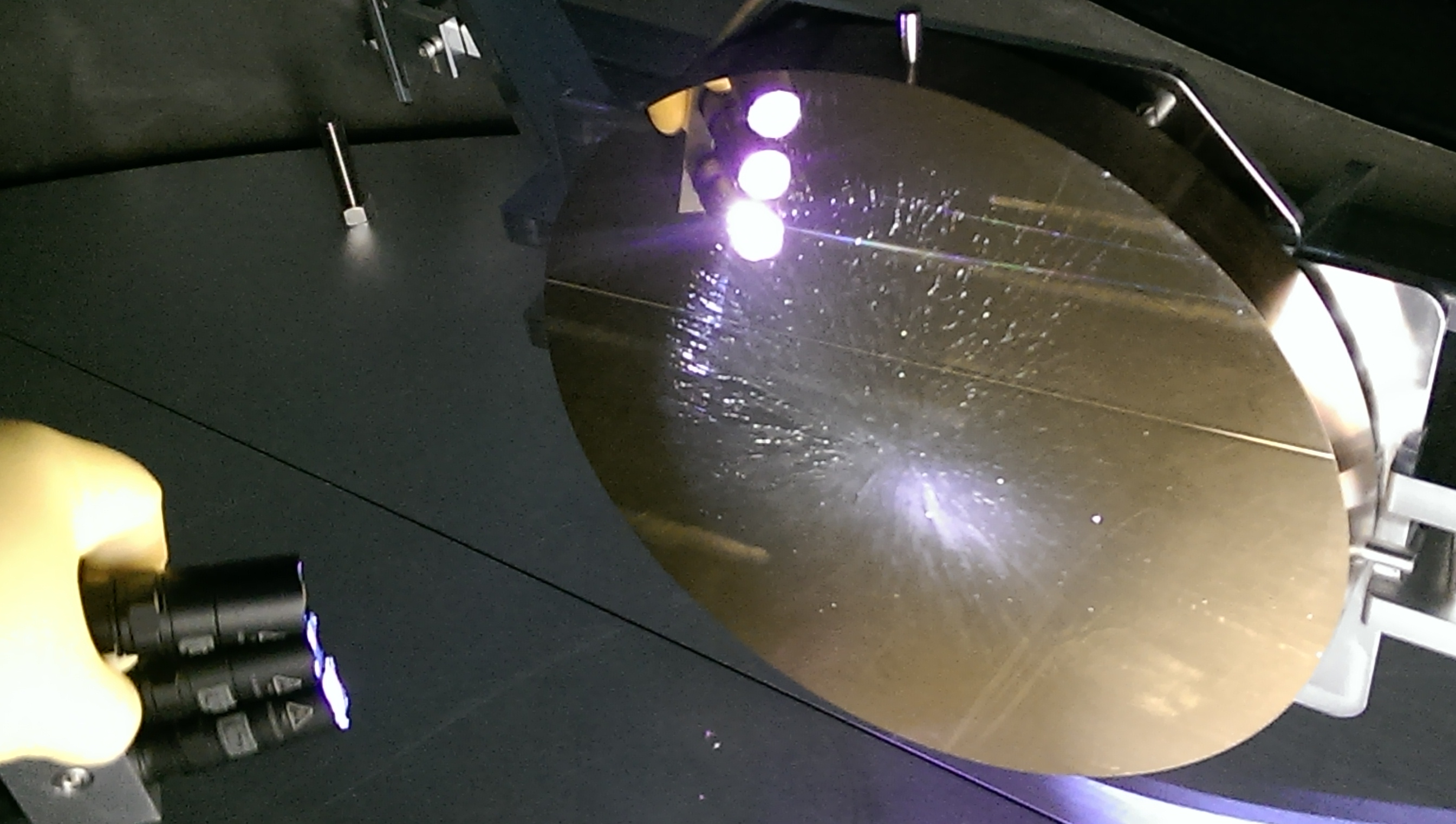
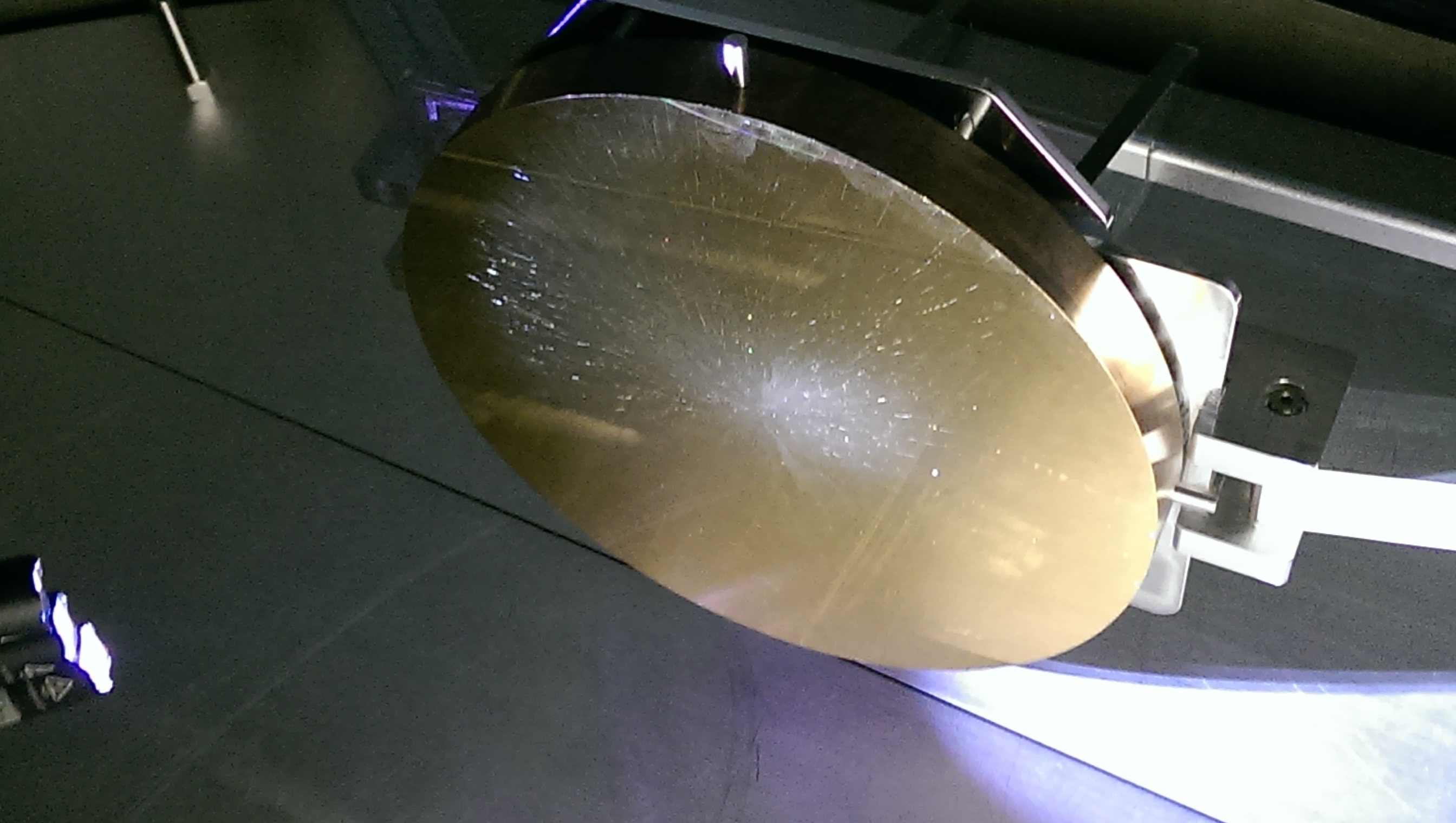
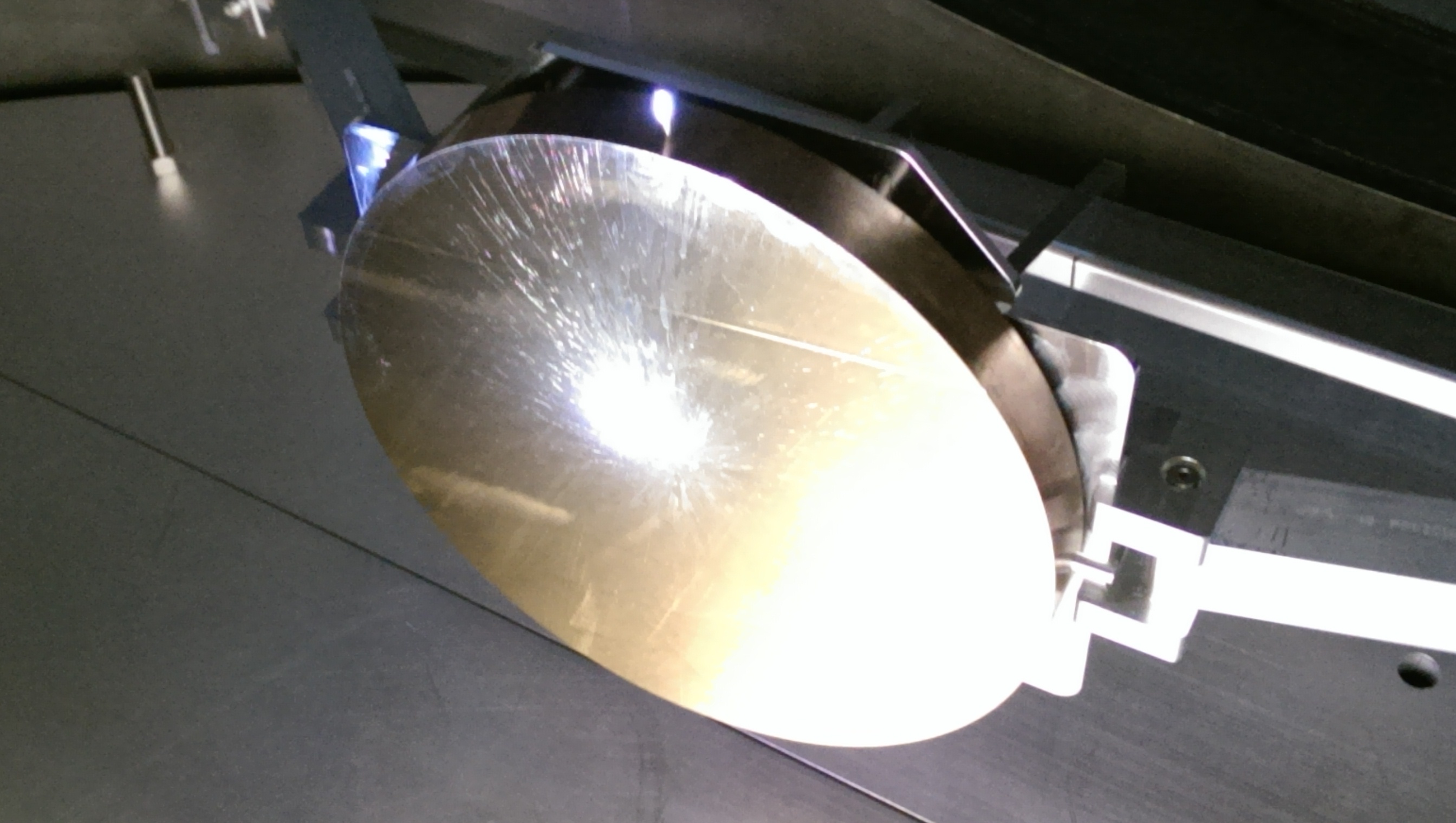
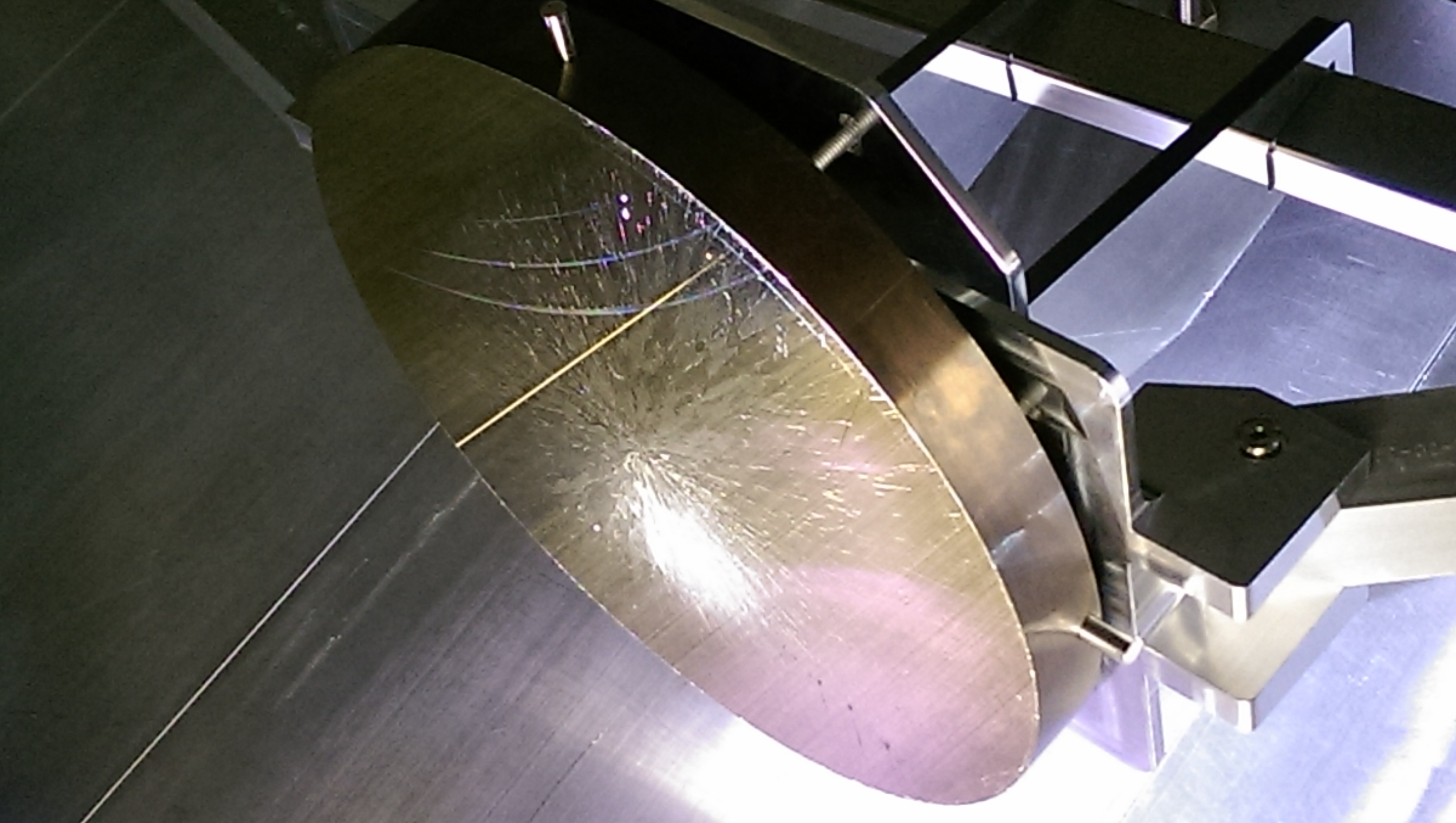
Here are the final alignment numbers for the ITMy, CPy, and the WBSC1 ACB:
ITMy
-
X axis position: -200.8 mm*
-
Target: -200.0 mm
-
Error: -0.8 mm
-
Tolerance: ±1.0 mm
-
Y axis position: 4982.7 mm
-
Target: 4983.1 mm
-
Error: -0.4 mm
-
Tolerance: ±3.0 mm
-
Z axis position: -79.2 mm
-
Target: -79.8 mm
-
Error: +0.6 mm
-
Tolerance: ±1.0 mm
-
Pitch: 366 µrad down**
-
Target: 340 µrad down (352 µrad down FC correction - 13 µrad up target pitch)
-
Error: 26 µrad down
-
Tolerance: ±50 µrad
-
Yaw: 17 µrad CW
-
Target: 0 µrad
-
Error: 17 µrad CW
-
Tolerance: ±50 µrad
* The X axis position is currently being held in place with a +300000 nm HEPI bias offset (see
alog 12922). Hugh plans to offload this bias onto the HEPI springs at a later date.
** We are assuming that when the FC is pulled the ITMy will move up in pitch by 352 µrad per
E1200791. This will put the final pitch of the ITMy at
14 µrad down. IAS equipment has been pulled from the spool for CPB install so we will be unable to verify this move. To get some idea of the pitch change we can weigh the FC after it has been removed and use the pitch compliance number in E1200791 to calculate the pitch change.
CPy
-
Pitch: 833 µrad down***
-
Target: 1.296 mrad down (to match the ITMy AR surface assuming zero ITMy pitch error; the ITMy has a vertical wedge of 0.075°, or 1.309 mrad down)
-
Error: 463 µrad up
-
Tolerance: ±1.4 mrad
-
Yaw: 31 µrad CCW
-
Target: 0 µrad (to also match the ITMy AR surface)
-
Error: 31 µrad CCW
-
Tolerance: ±1.4 mrad
*** This is the actual pitch of the CPy. The listed error is relative to where the CPy needs to be to be parallel with the ITMy AR surface, assuming the ITMy has zero pitch error; this does not include any FC correction done on the ITMy. Since we cannot verify the ITMy pitch after FC removal, we also cannot verify the CPy pitch relative to the ITMy AR surface after FC removal. We have to assume that E1200791 is correct (we have only been able to test this one time at the ETMy, which moved upward by 442 µrad, but one data point does not a trend make) and that the ITMy will pitch up by ~352 µrad upon FC removal. Therefore our expected relative pitch between ITMy and CPy upon FC removal is 490 µrad up (14 µrad down ITMy HR pitch + 1309 µrad down wedge - 833 µrad CPy pitch = 490 µrad up relative pitch). As stated above we can weigh the FC to get some idea of the pitch change.
ACB (relative to the ITMy)
-
Lateral position error: -0.3 mm
-
Vertical position error: +1.2 mm
This completes IAS alignment of ITMy; our equipment has been removed from the Y manifold spool area to allow for the Cryopump Baffle installation. This also ends the IAS alignment of the aLIGO H1 interferometer.


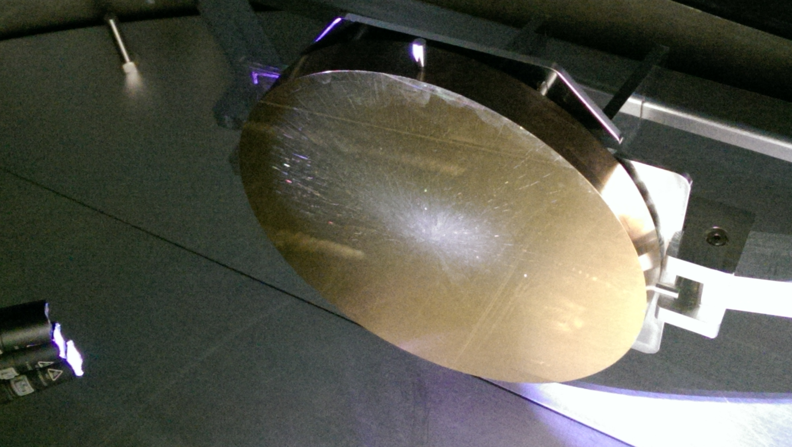

 Unfortunately the mass of the FC came in under the expected mass and below the allowed variation; if you look at E1200791 the allowed variation of the FC mass is 0.159 g, which results in a low end mass expectation of 2.955 g, not the 2.8 g I measured.