There have been a few other alogs about this already:
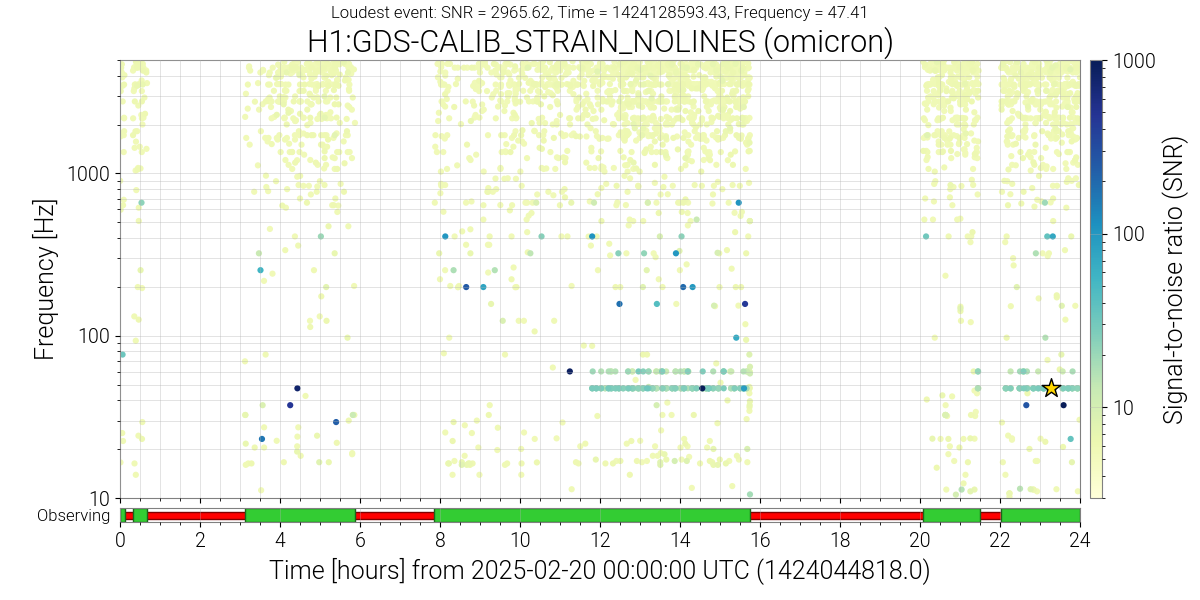
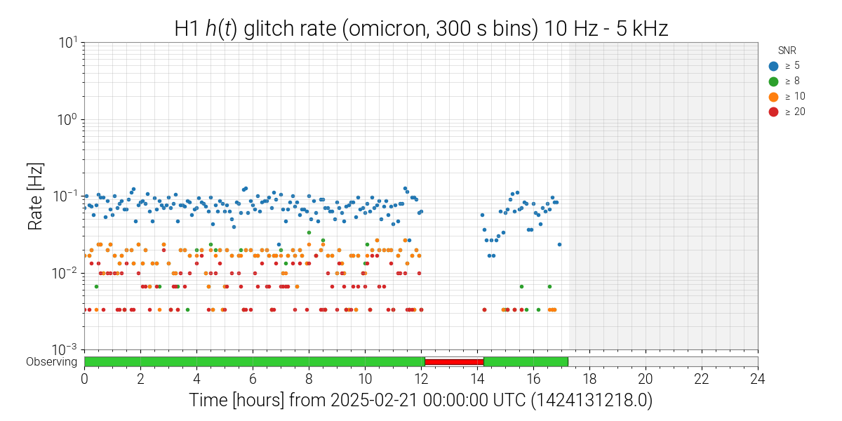
H1's range is slighty improved after the initial drop (possibly due to PRCL and A2L tuning in the commissioning window), but the large glitches are still present. They were not present in the early part of yesterday's lock, but re-appeared after TJ took a calibration measurement around 22 UTC (were present all night and caused a retraction of a GW alert), and they are not present so far in the current lock, which was automatic. Looking at the summary page plots, the glitches that come and go are those with SNR between 10 and 30, at 60 and just below 50 Hz. (I can't read the precise frequency from the summary page plot, to know if these glitches line up with the PR3 roll mode well or not). When the glitches are on, they have a rate of something like 2e-2 Hz (between SNR of 10-20), which means roughly a glitch every 50 seconds, more if we include the SNR 20-30 glitches. Hveto doesn't identify an auxillary channel that can veto these glitches.
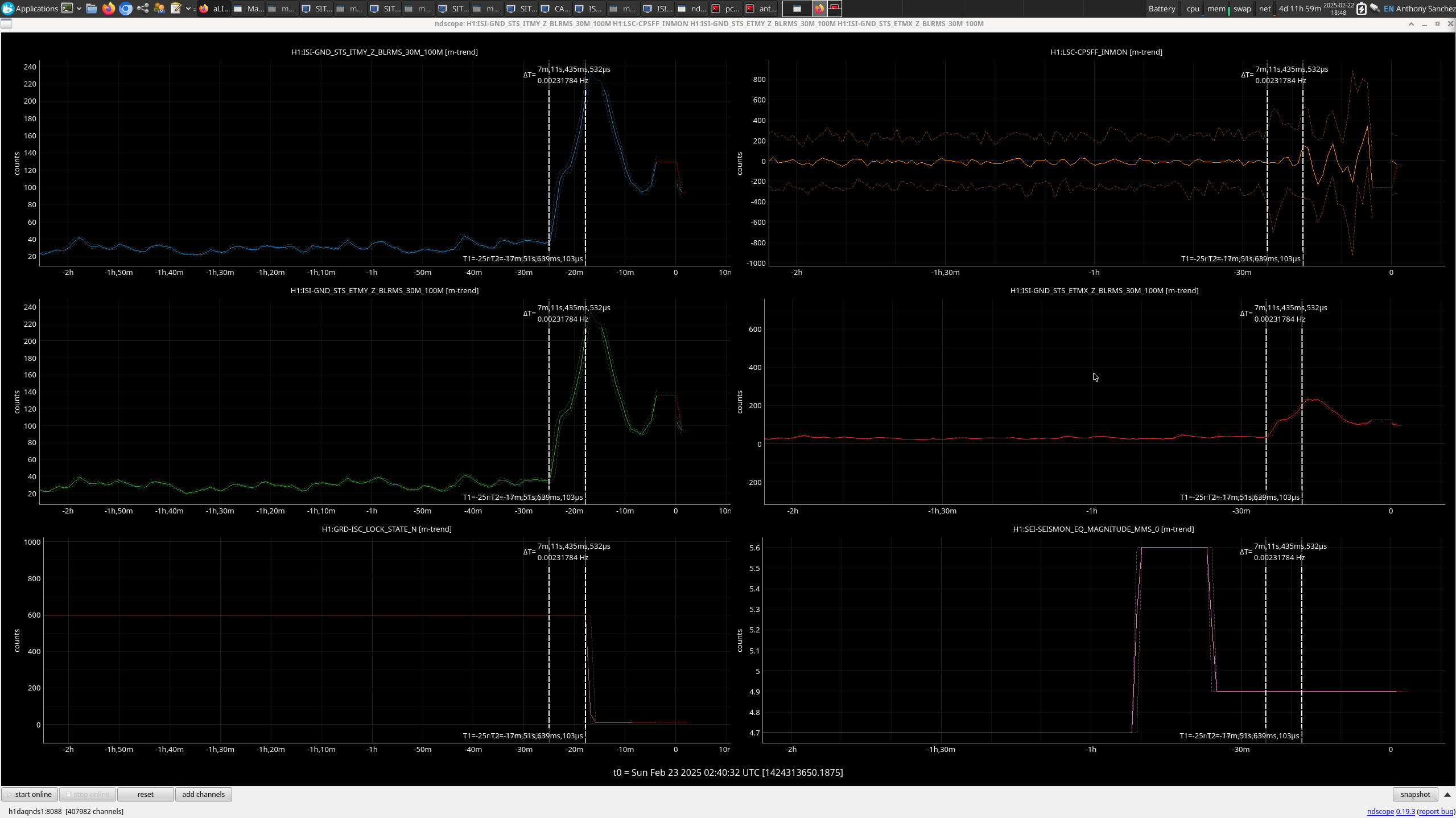
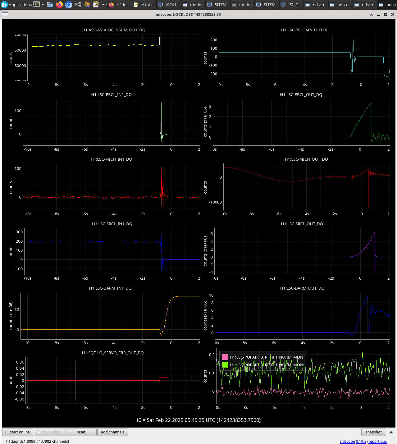
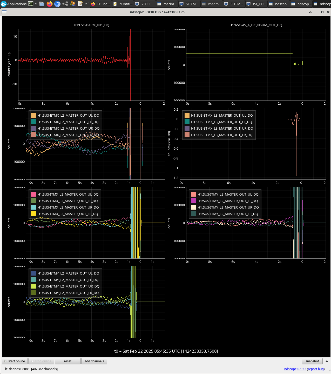
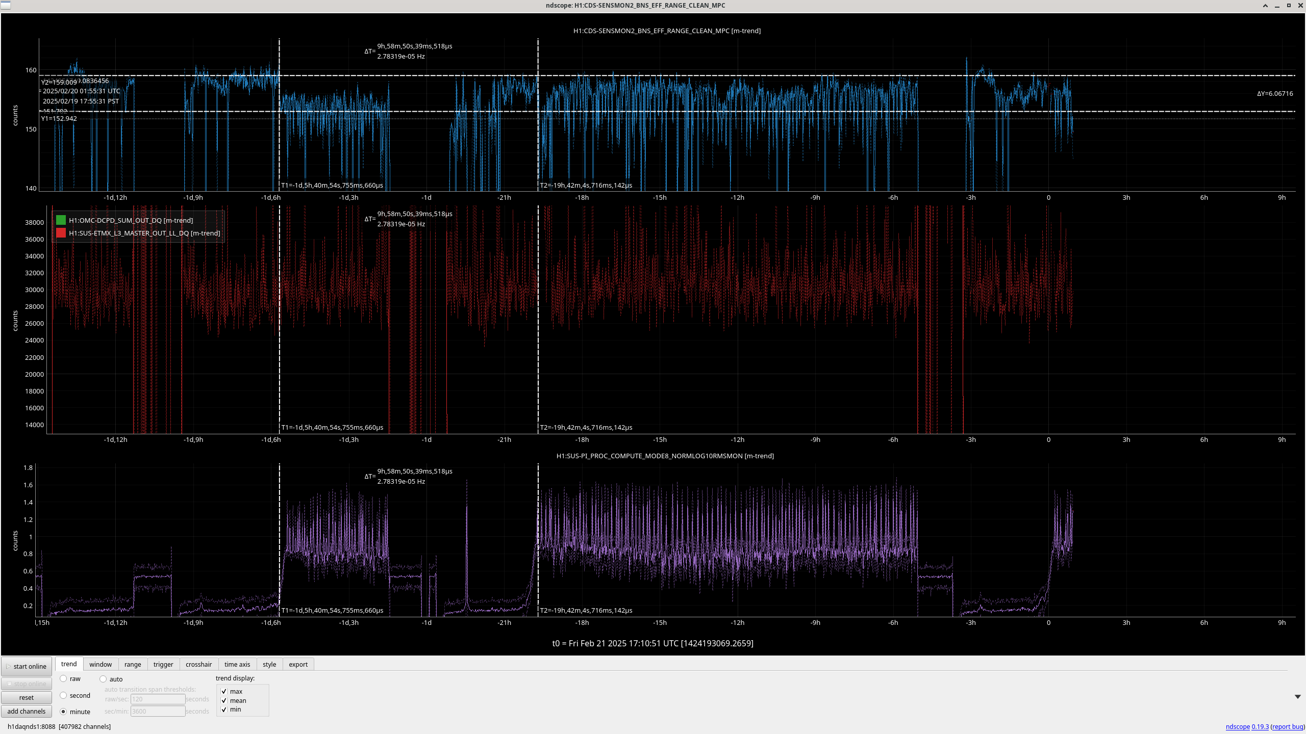
Looking at the range plot, there seem to be pretty regular drops in range when the glitches at 50 + 60 Hz are present, zooming in the spacing between these range drops is 5-6 minutes, although I'm using a channel that only updates every minute. Looking at DCPD sum or ESD drive channels time series don't show an obvious way to get a better handle on the timing of these larger, less frequent glitches.
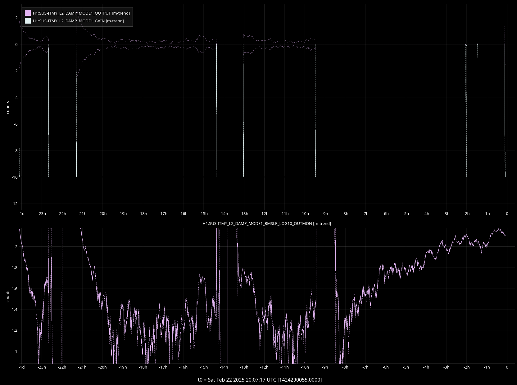
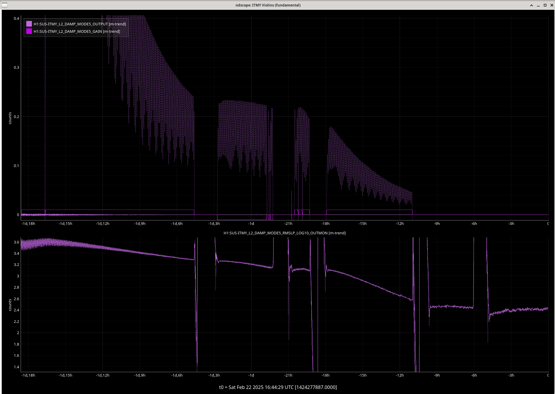
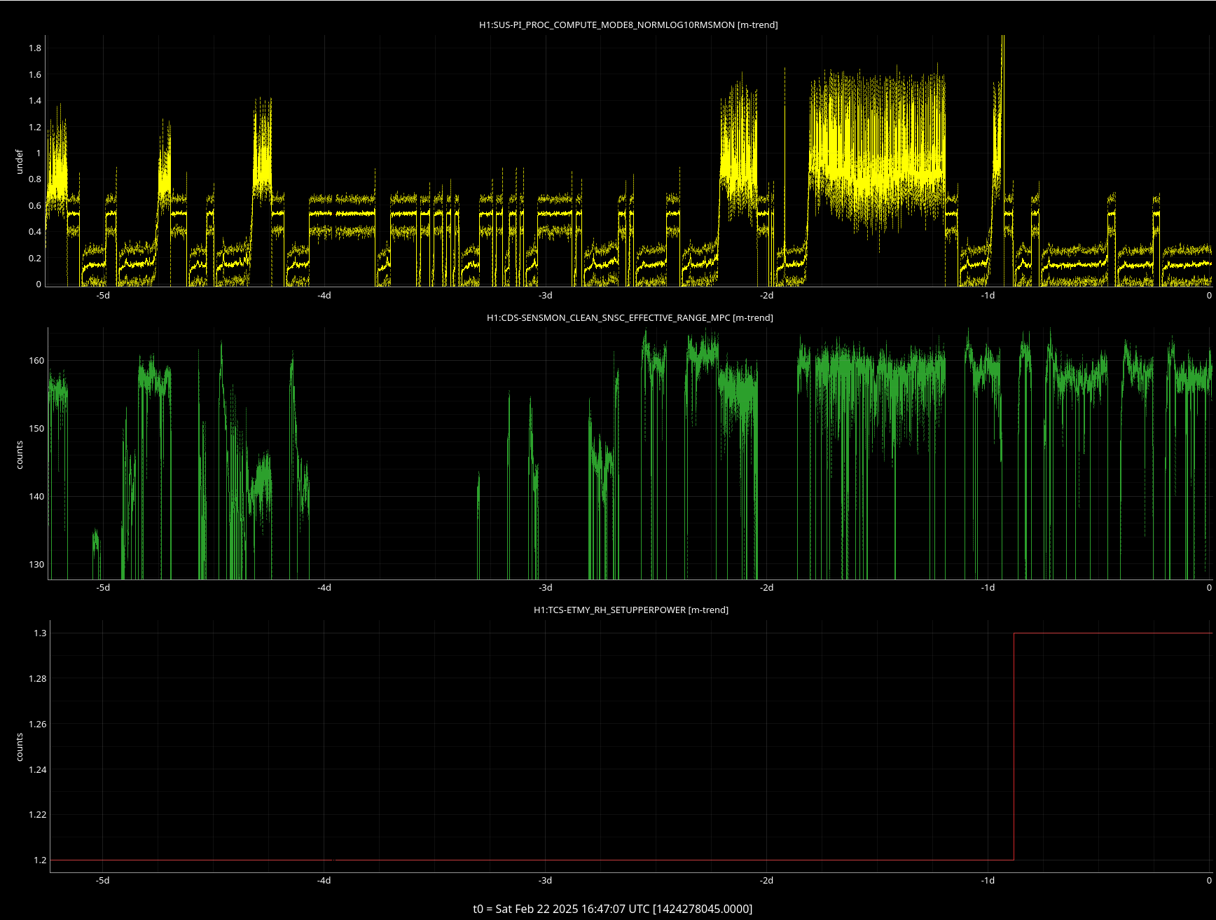
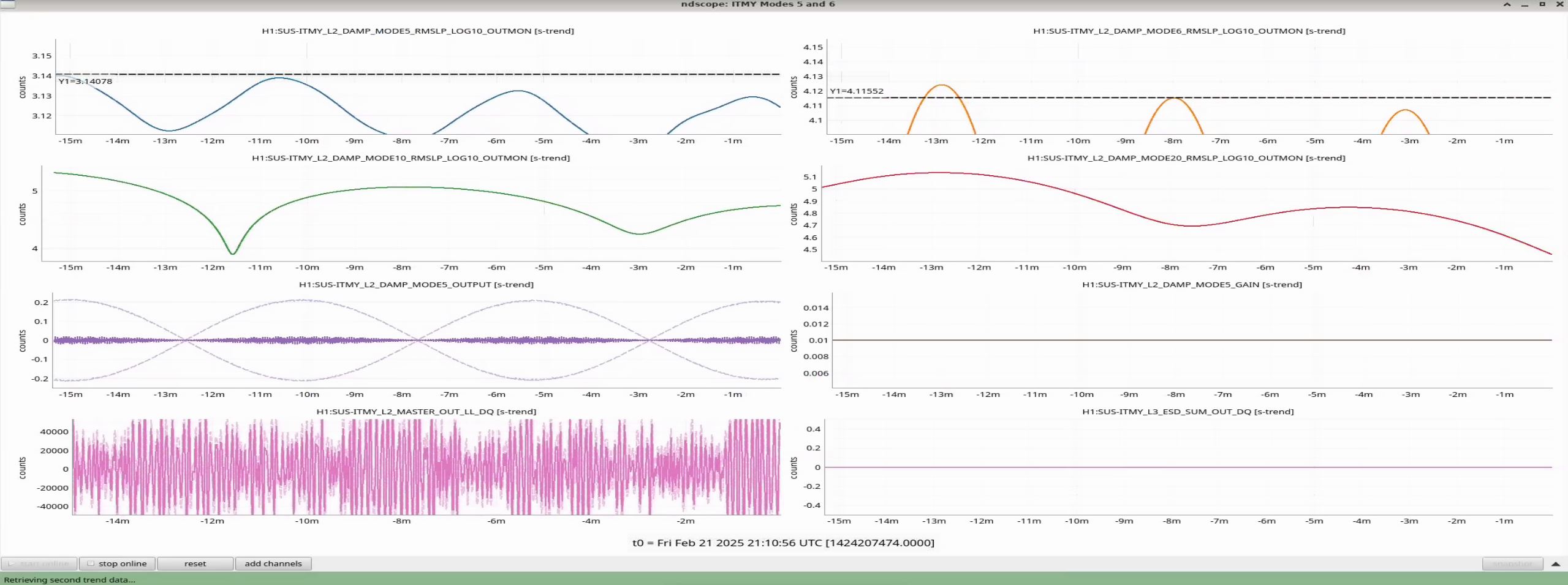
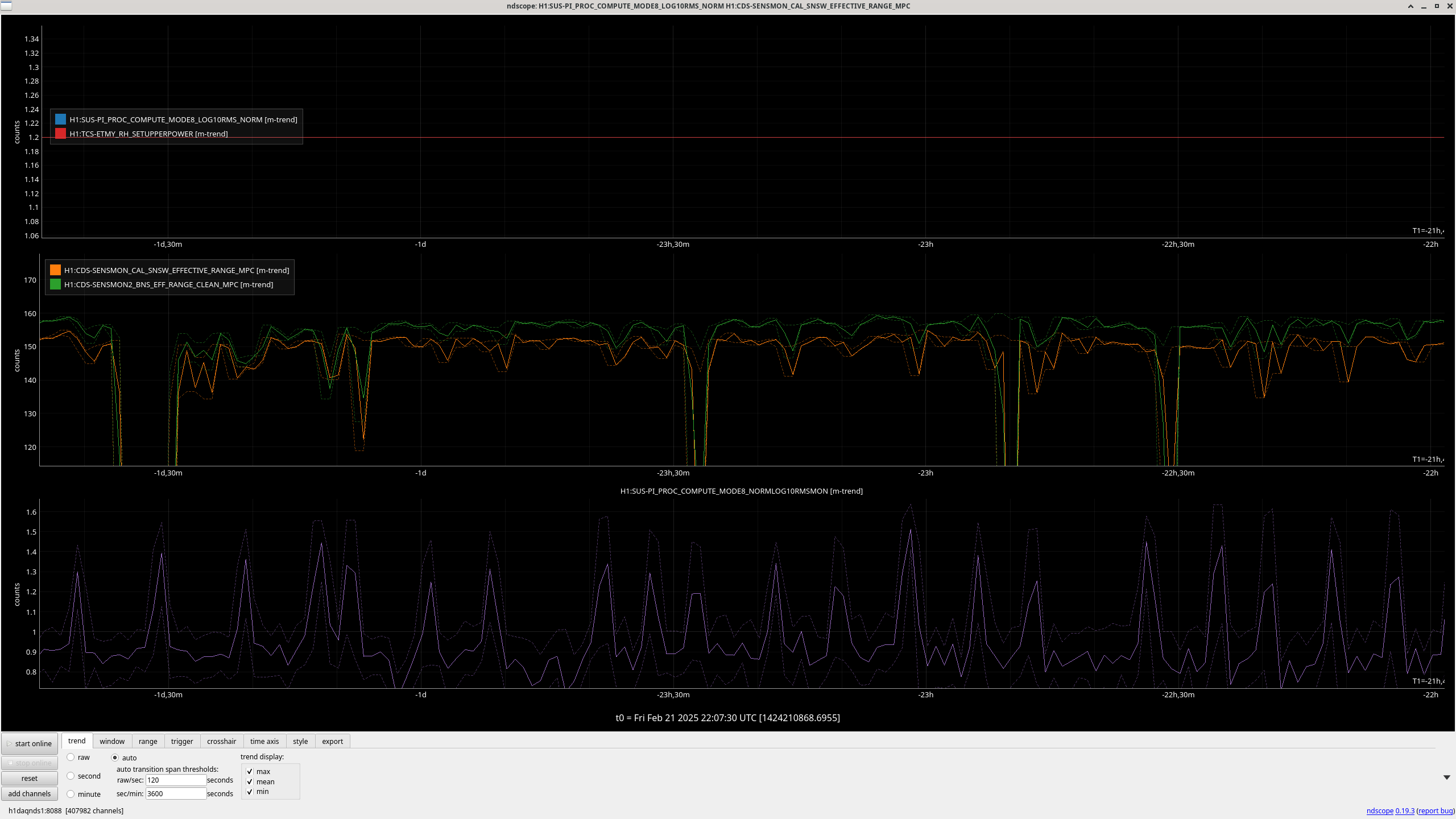
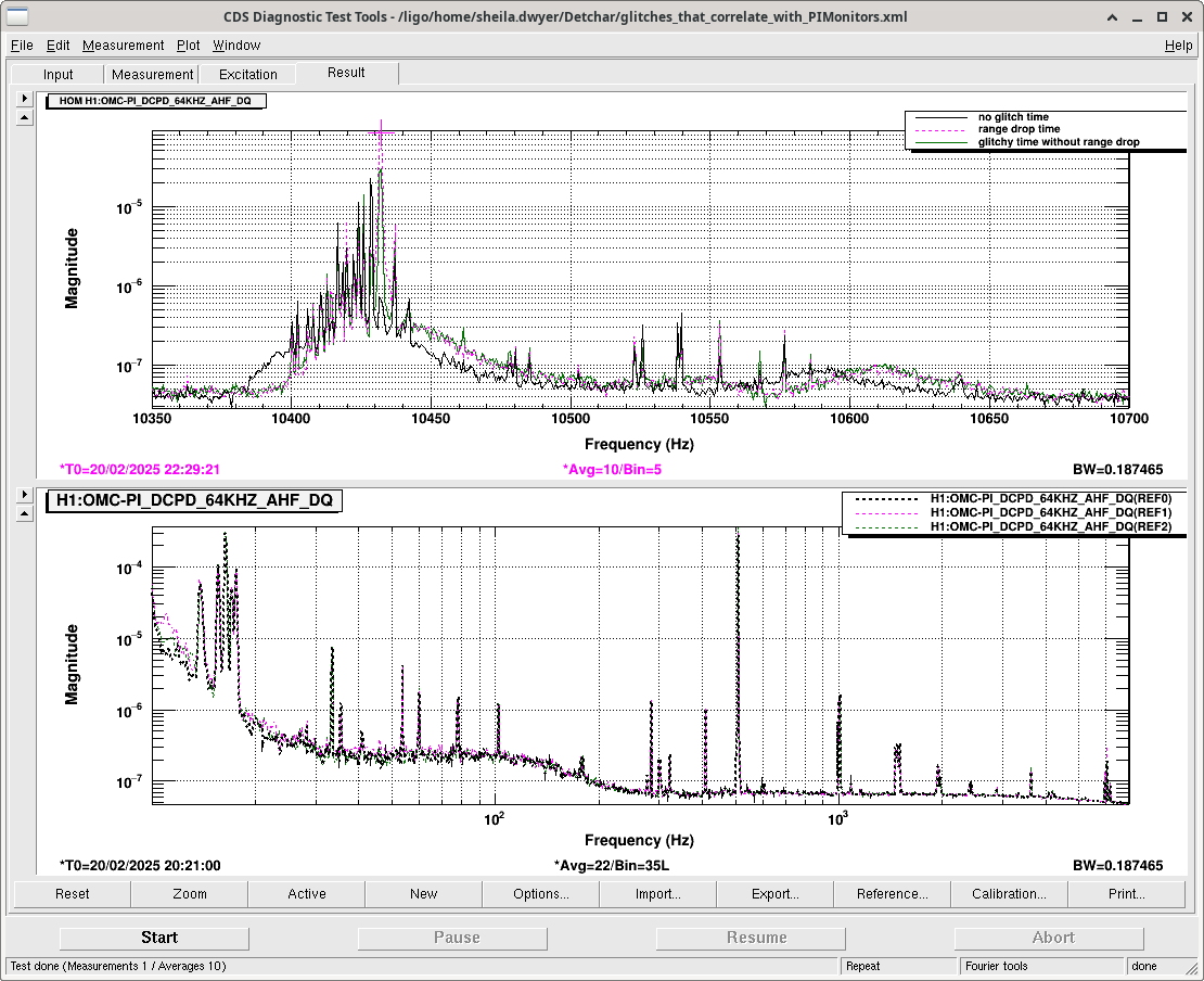
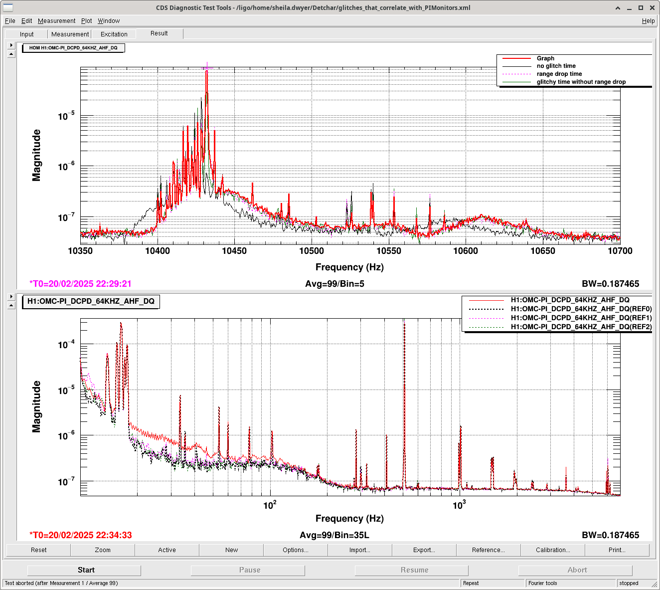
The correlation with 82944 the PI channel found by Jane's Lasso run seems to continue where the PI channel keeps being rung up in the time periods when the range has these drops every 5 minutes.
Editing to add:
It looks like the MODE8 channel got elevated like this for the first time on Feb 5th, and there have been a number of incidences where this channel was elevated with glitches at 60 Hz and just below 50: