This morning I restarted the suspension guardian nodes to bring them up to date with the changes Arnaud and I made yesterday (alog 11982). Almost immediately the BS started oscillating in yaw. I tracked the issue down to the BS optical lever loops (H1:SUS-BS_M2_OLDAMP_Y in particular). I believe cycling GRD:SUS_BS through it's graph, which shuts off the damping loops and alignments offsets, is what set it off. Even after re-enabling the damping and alignment offsets did not fix the issues, as the OPDAMP filters were rung up (the outputs continued to oscillate even after the inputs were shut off). After shutting off the OLDAMP loops the oscillations damped down, and once I cleared history and re-enabled the OLDAMP loops things came back to normal.
Clearly one problem is that the SUS_BS guardian is not handling the optical lever loop in the BS. It looks like only BS has OLDAMP engaged at the moment (excetly ITMX, which I'll mention in a minute). The SUS guardian probably should be making sure the OLDAMP controllers are shut off when the optics are not aligned. I'll work with the SUS team to get this fixed.
I'm not sure why ITMY has OLDAMP engaged where as the rest of the main suspensions do not. I'll look into that as well.


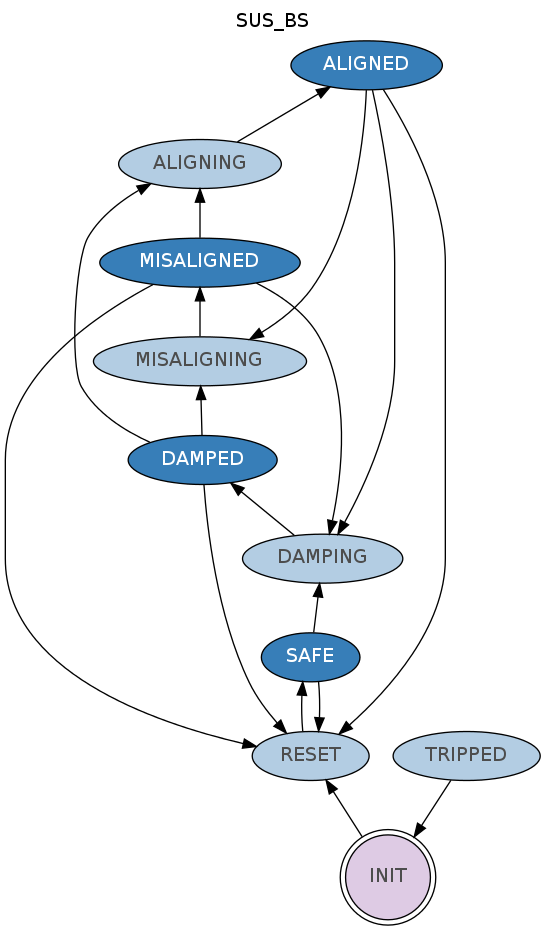
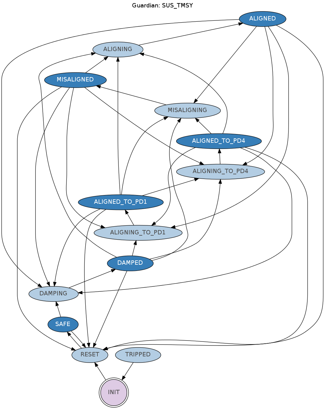
Guardian was modified and now TURNS OFF the oplev feedback when going to the MISALIGNED / DAMPED or SAFE state, so this kind of situation shouldn't happen anymore.
I reloaded guardian on suspensions with optical lever : BS ETMX ETMY ITMX ITMY PR3
SUS.py was commited under version #8042 of the svn