I placed the IR oz optics fiber coupled laser on ISCEX, with a colimator and two steering mirrors.
When I first got there the green QPD cenering servos were not working, it seems that the matrix elements changed in early june so I did a burt restore to June 1st. The servos worked fine after that.
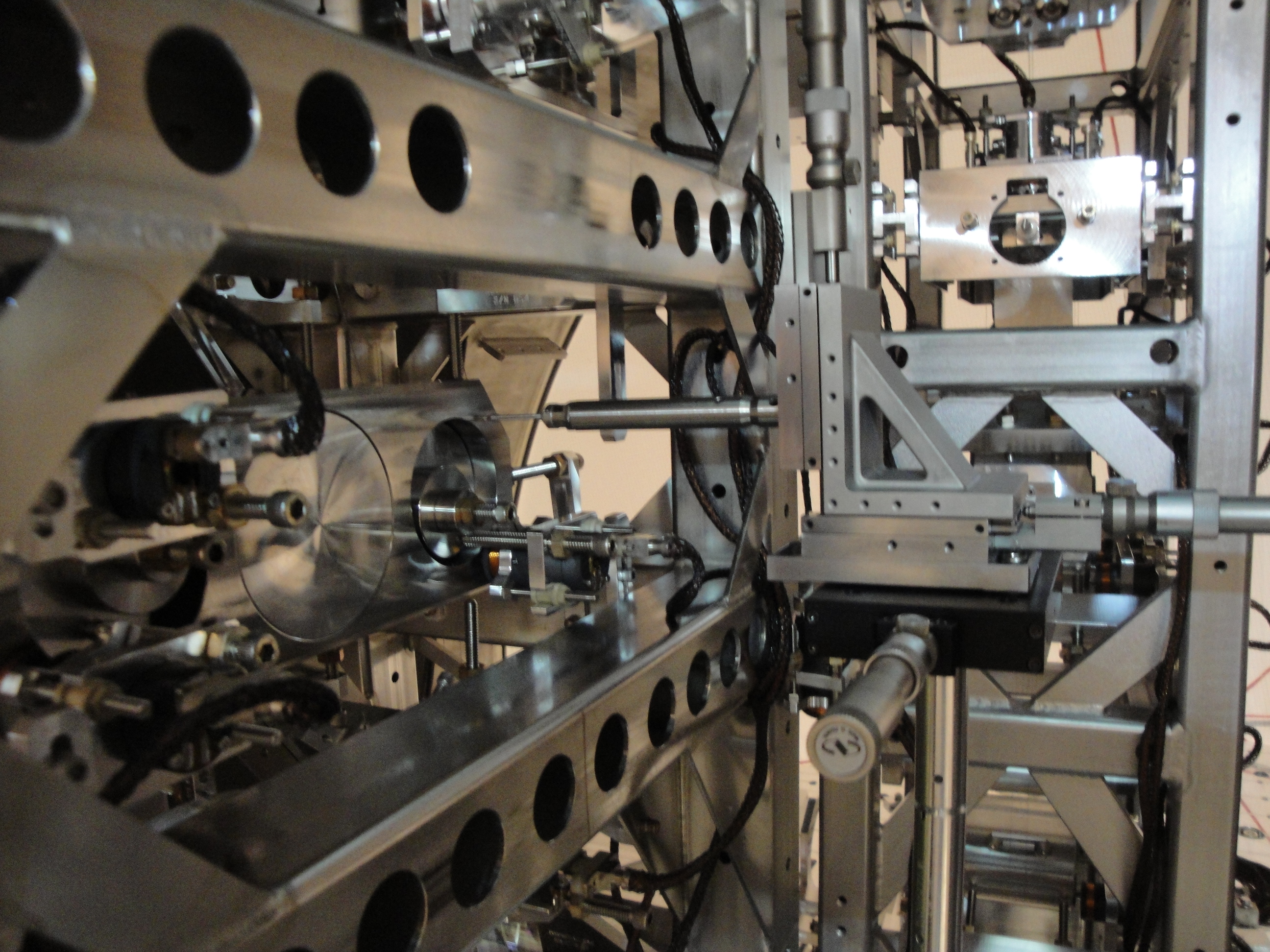
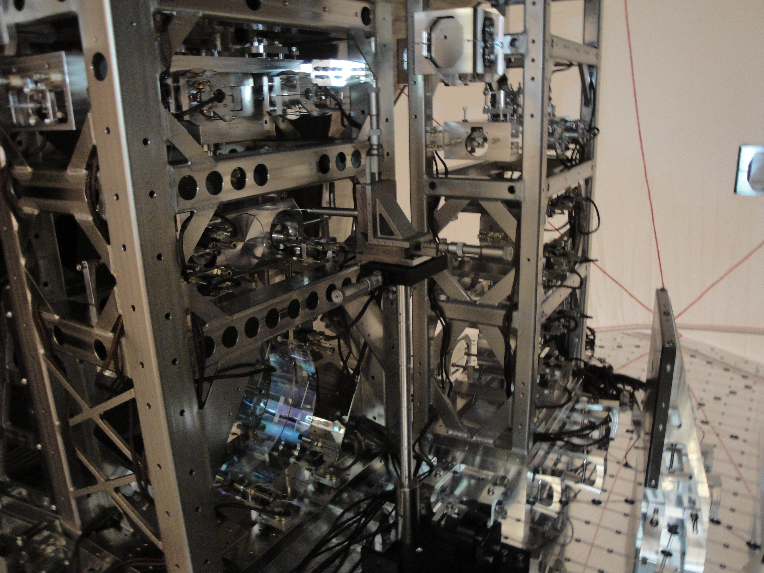
I only saw one green beam in the IR trans path at the PD this time, this is different from what I saw in May (alog 12161). I aligned the IR laser along the path of the green light coming out of the chamber using the mirrors I had added to the table, and saw a retroreflected beam coming back out of the chamber. This beam is somewhat large.
I'm done using the laser at end X, and have returned the key to the control room. If anyone wants to transition to laser safe while preparing for the vent, that's fine.