Aidan, Thomas, Matt, Jason
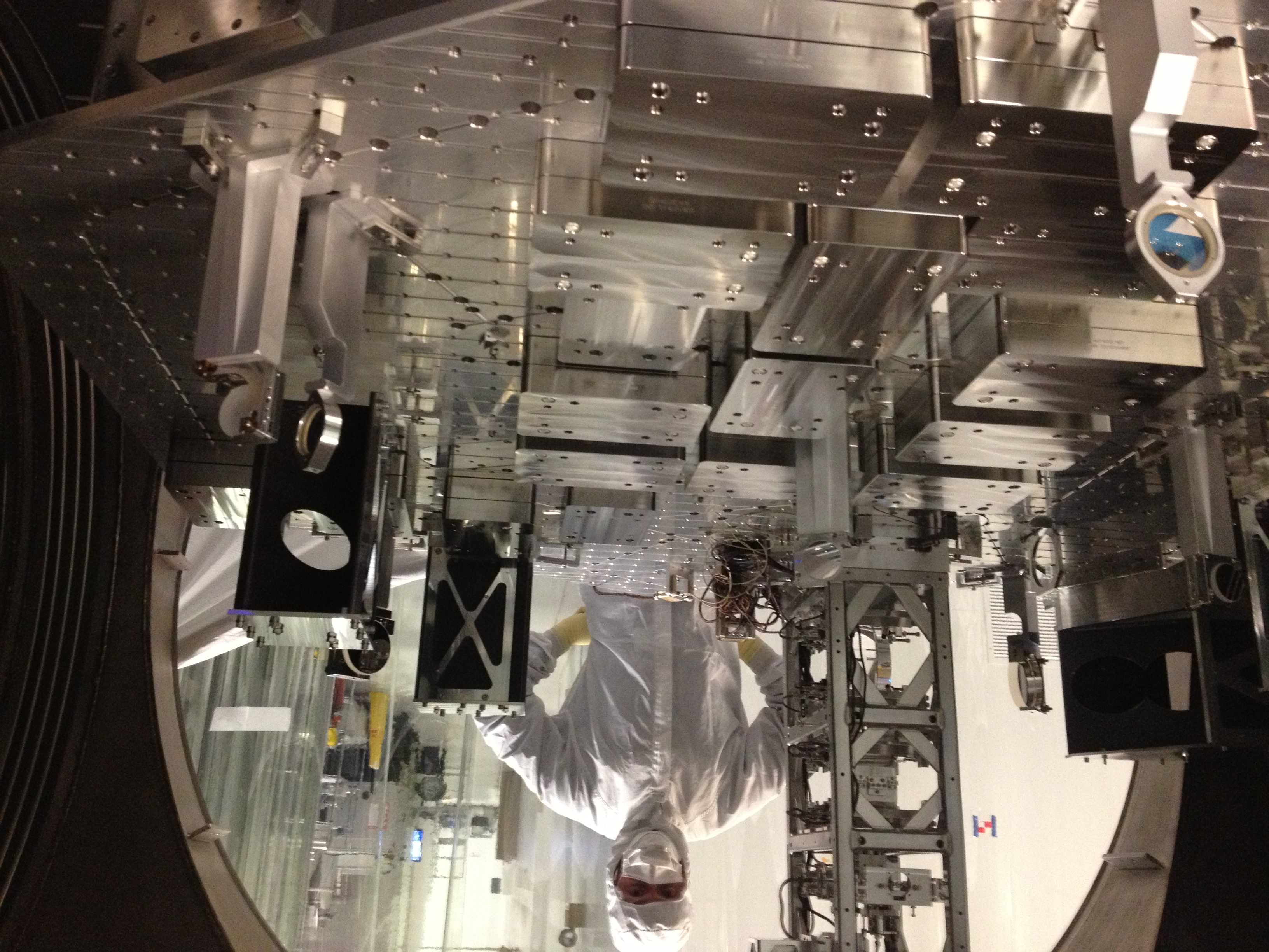
We aligned the in-chamber HAM4 HWS optics using the IAS beam this afternoon.
1. Matt adjusted the alignment of SR3 to center the IAS beam on SR2.
2. I confirmed the beam was centered on HWSY STEER M1 (the transmission through SR2).
3. I adjusted HWSY STEER M1 to center the beam on HWSY STEER M2
4. Matt adjusted HWSY STEER M2 to center the beam on HWSY STEER M3
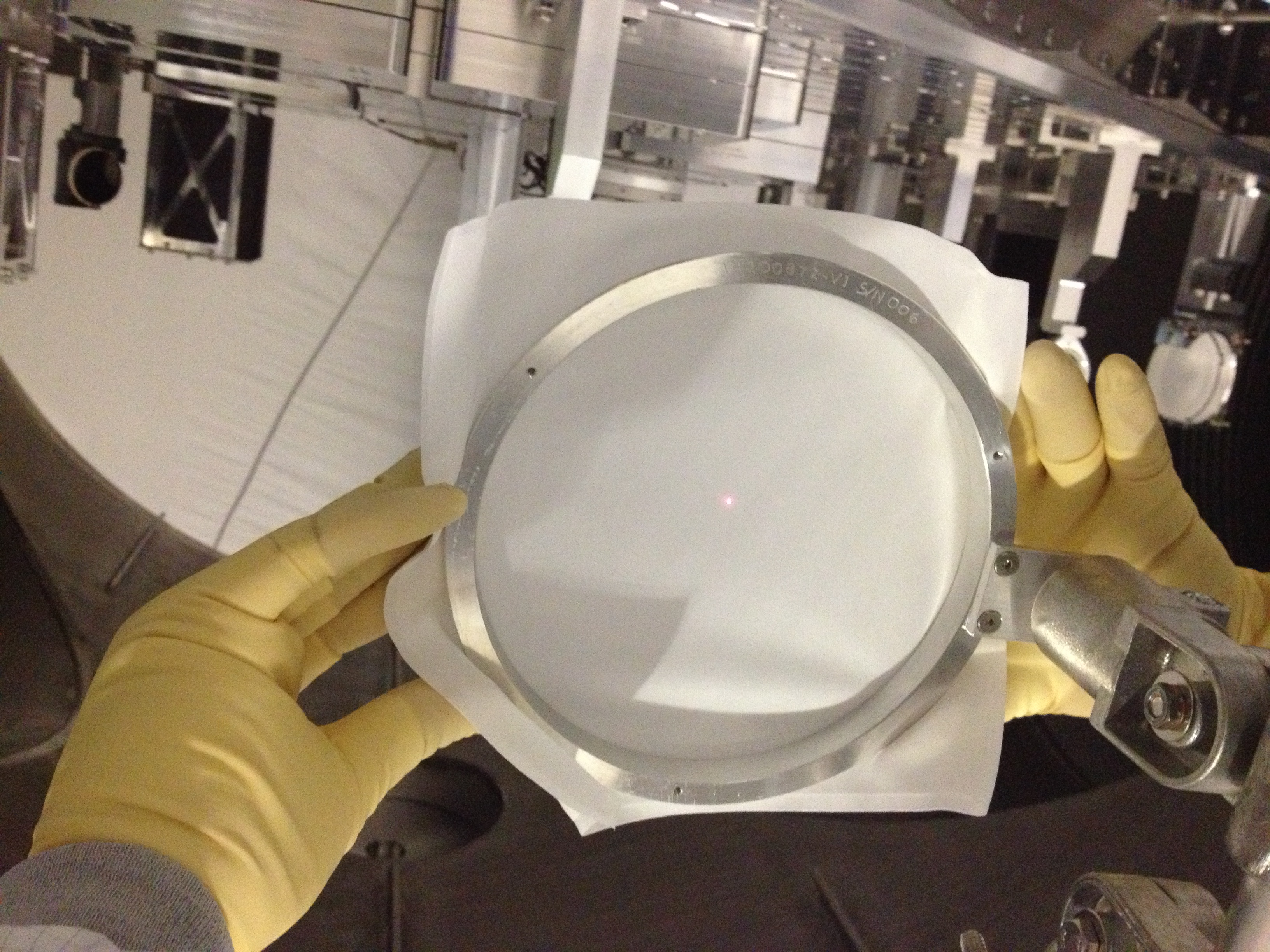
5. Matt adjusted HWSY STEER M3 to center the beam on the HWSY VAC LENS. This also centered the red beam on the installed viewport emulator.
6. Matt adjusted the HWSY DCBS by M2 such that the reflection off this optic, which will be 1064nm leakage, was captured by the HWSY scraper baffle (in the crook of the baffle on the -Y side of it). He also confirmed that the beam was centered on that DCBS. There were two reflections from the DCBS that were horizontally separated.
7. I adjusted HWSX STEER M1 to center the beam on HWSX STEER M2.
8. Matt adjusted HWSX STEER M2 and M3 to center the beam on M3 and on the viewport emulator (without HWSX VAC LENS installed)
9. Matt installed HWSX VAC LENS to return the beam to the same point on the viewport emulator
10. Matt adjusted HWSX DCBS to put the reflection of the red beam off that optic into the crook of the HWSX scraper baffle in the -Y direction. There were two reflections from the DCBS - one was at the same height as the incoming beam and the other was angled down and in the -Y direction.
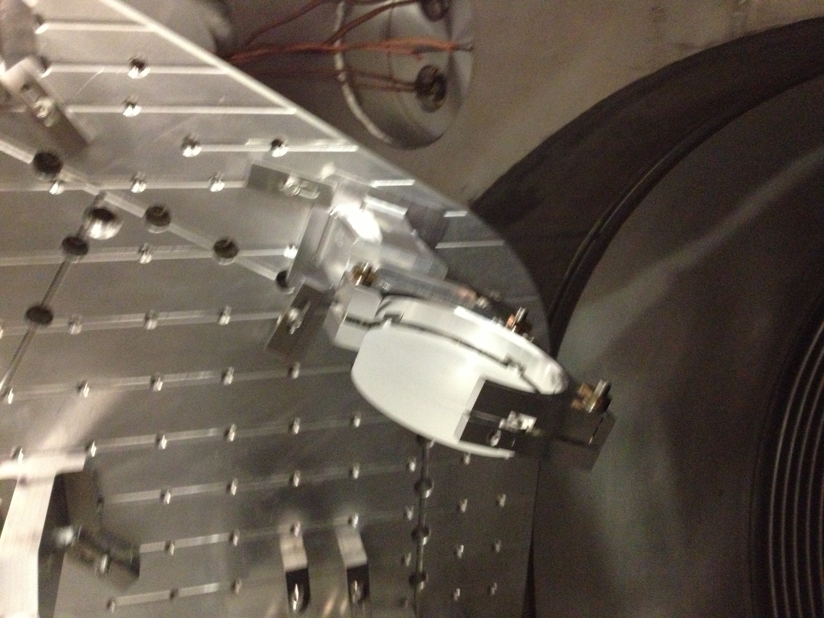
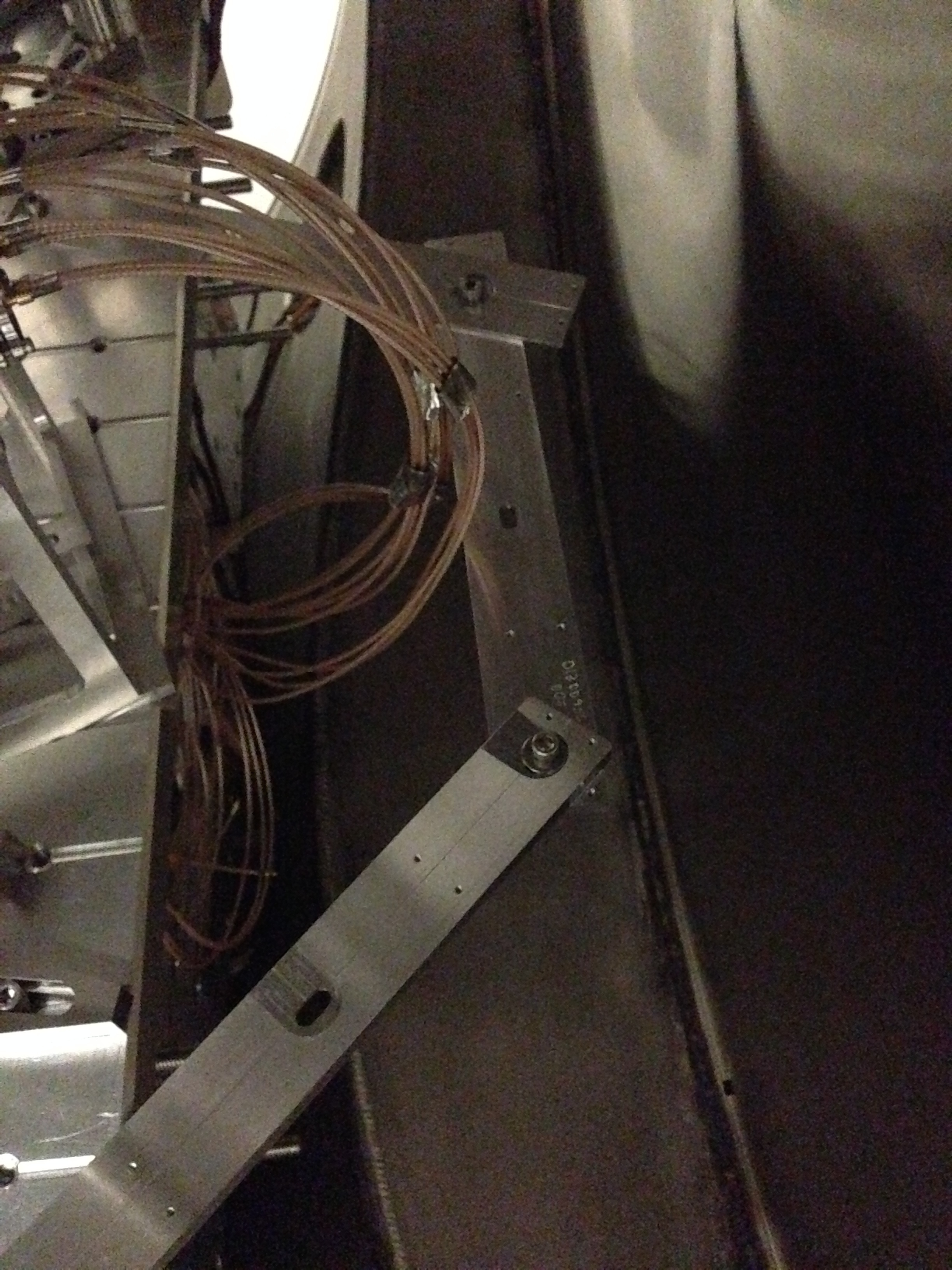
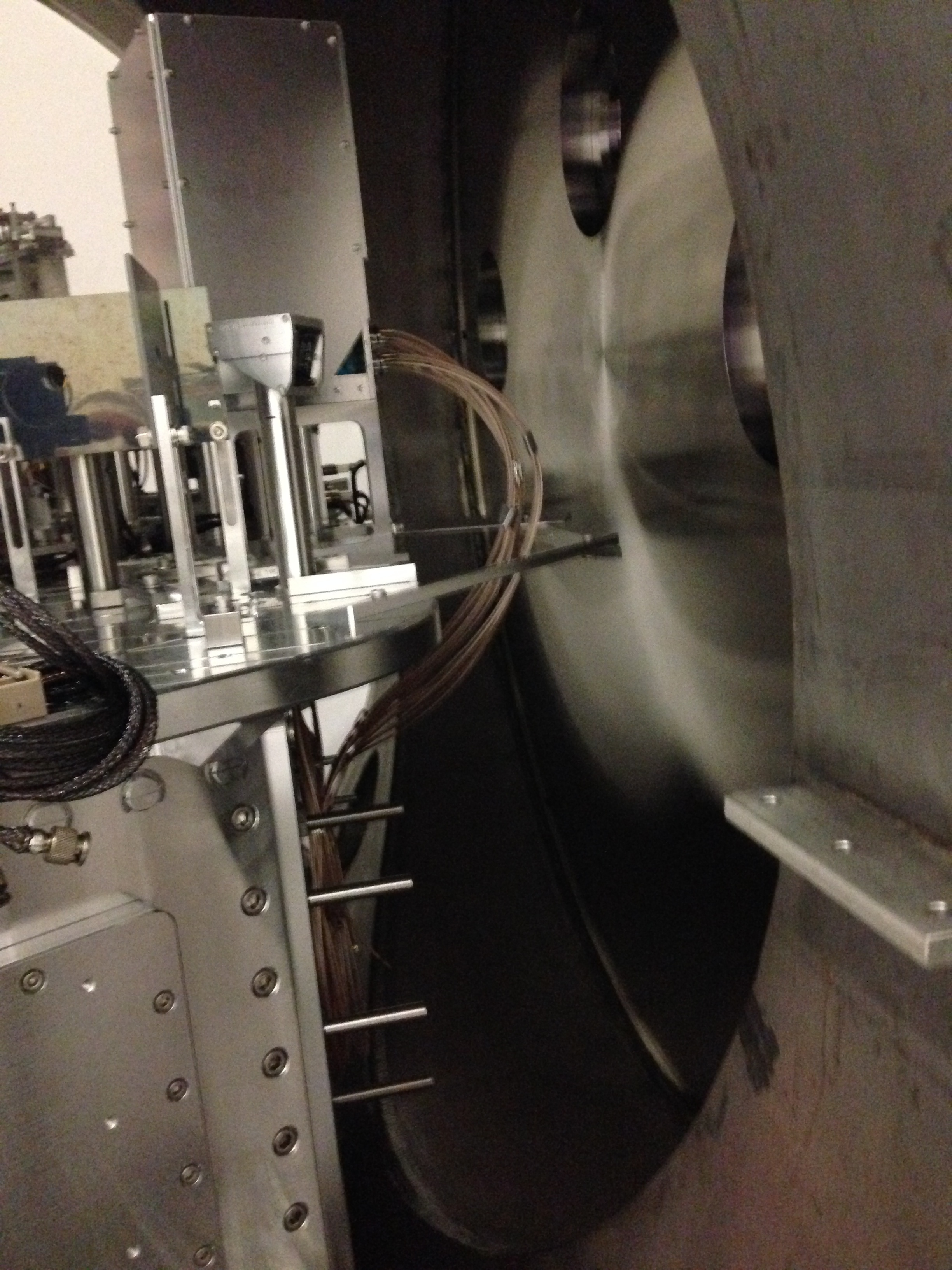
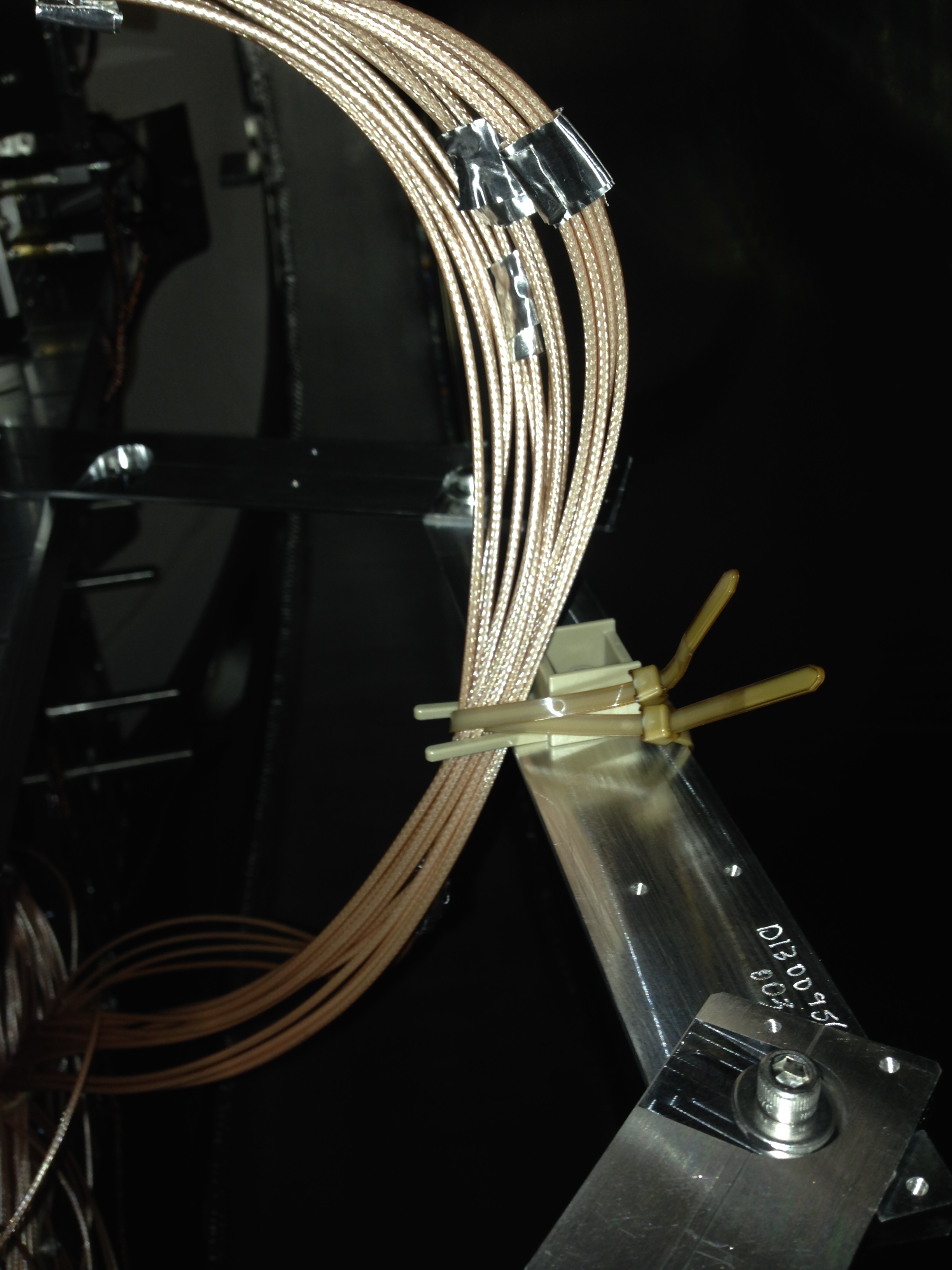
11. Since I'd forgotten this step to start with, I moved HWSX STEER M1 ~5mm parallel to its surface to make sure the beam was centered on the aperture of that optic. The distance of the beam from the edge of the aperture is shown in the attached PDF. We also placed a target far downstream of this optic, noted the position of the beam before the optic was moved and returned the beam to that position after the optic was moved to ensure the alignment was not affected.
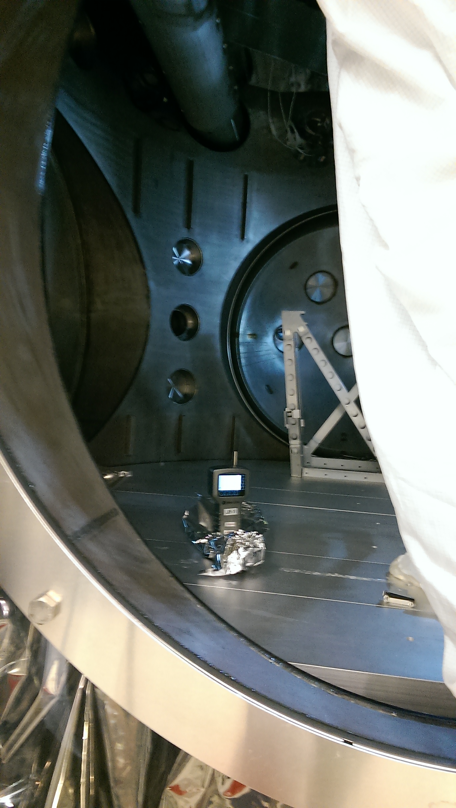
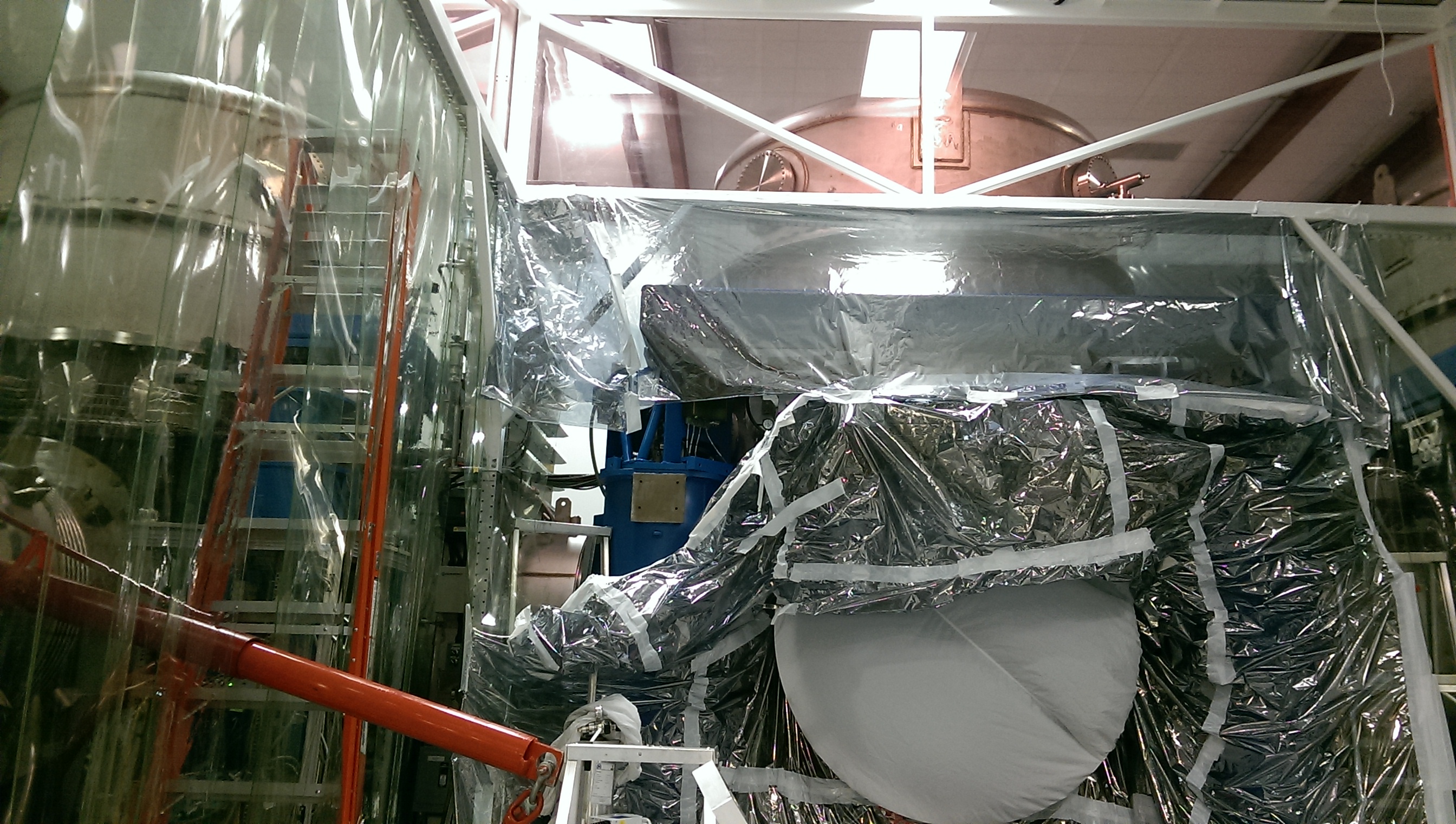
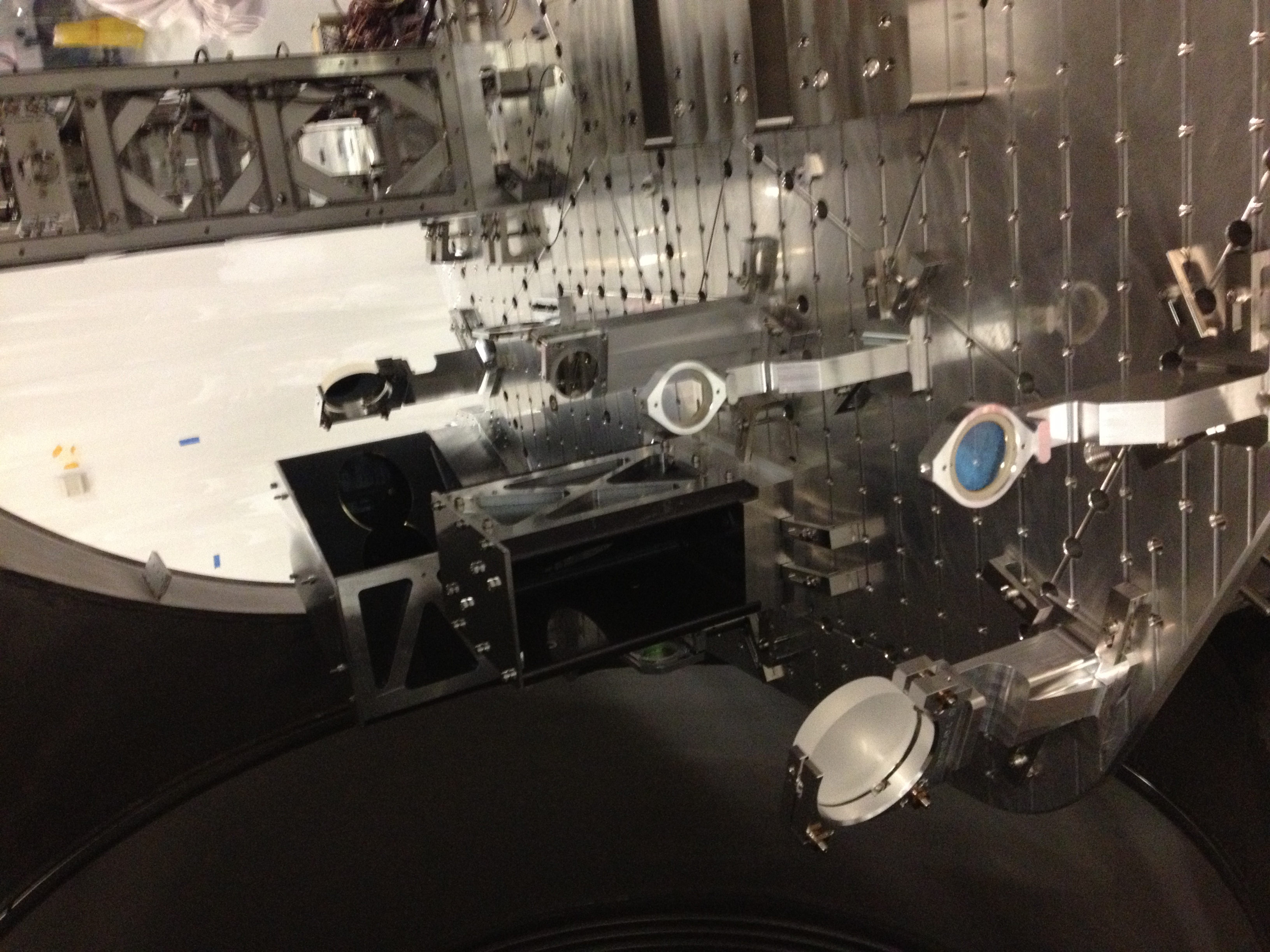
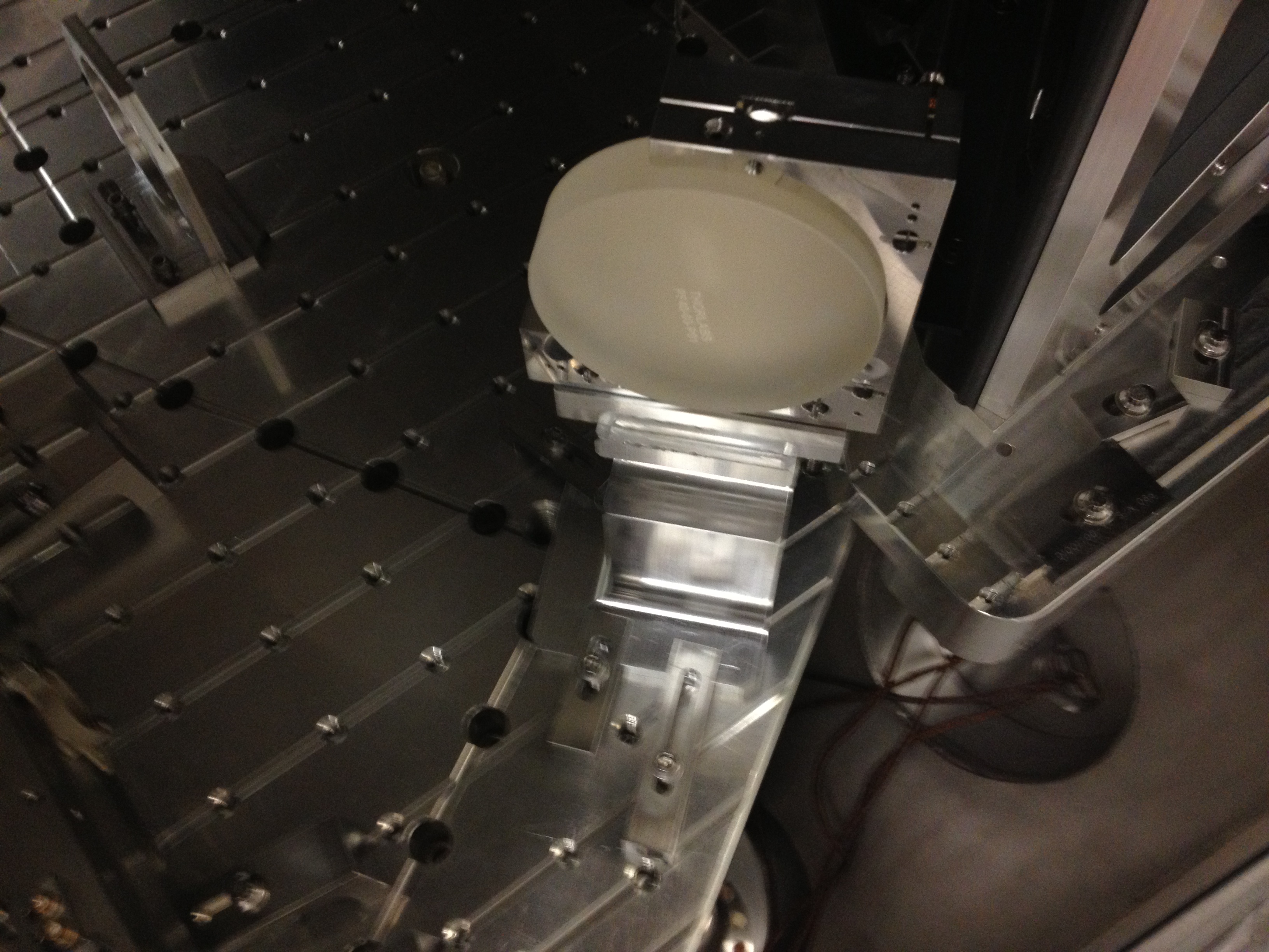
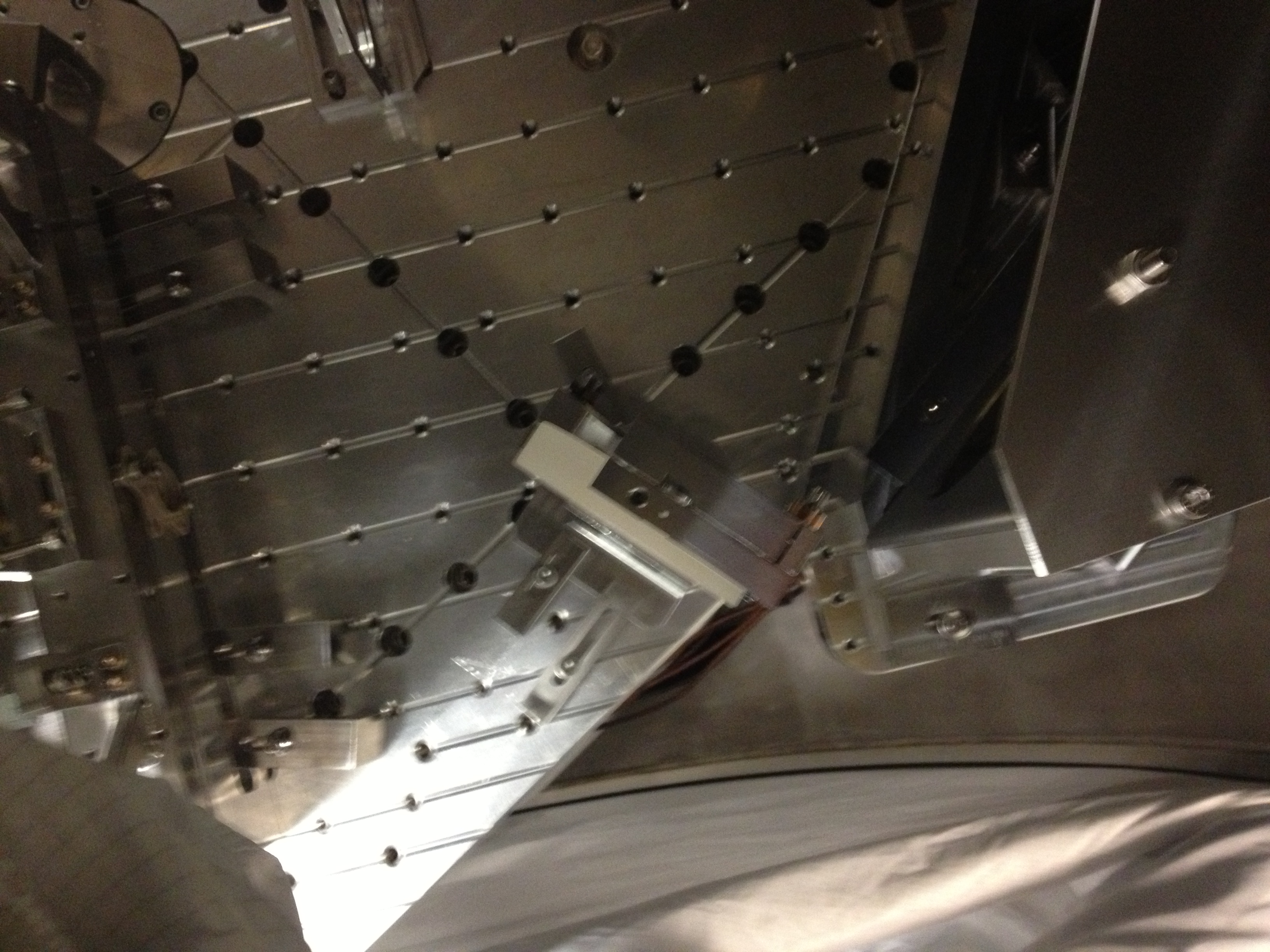
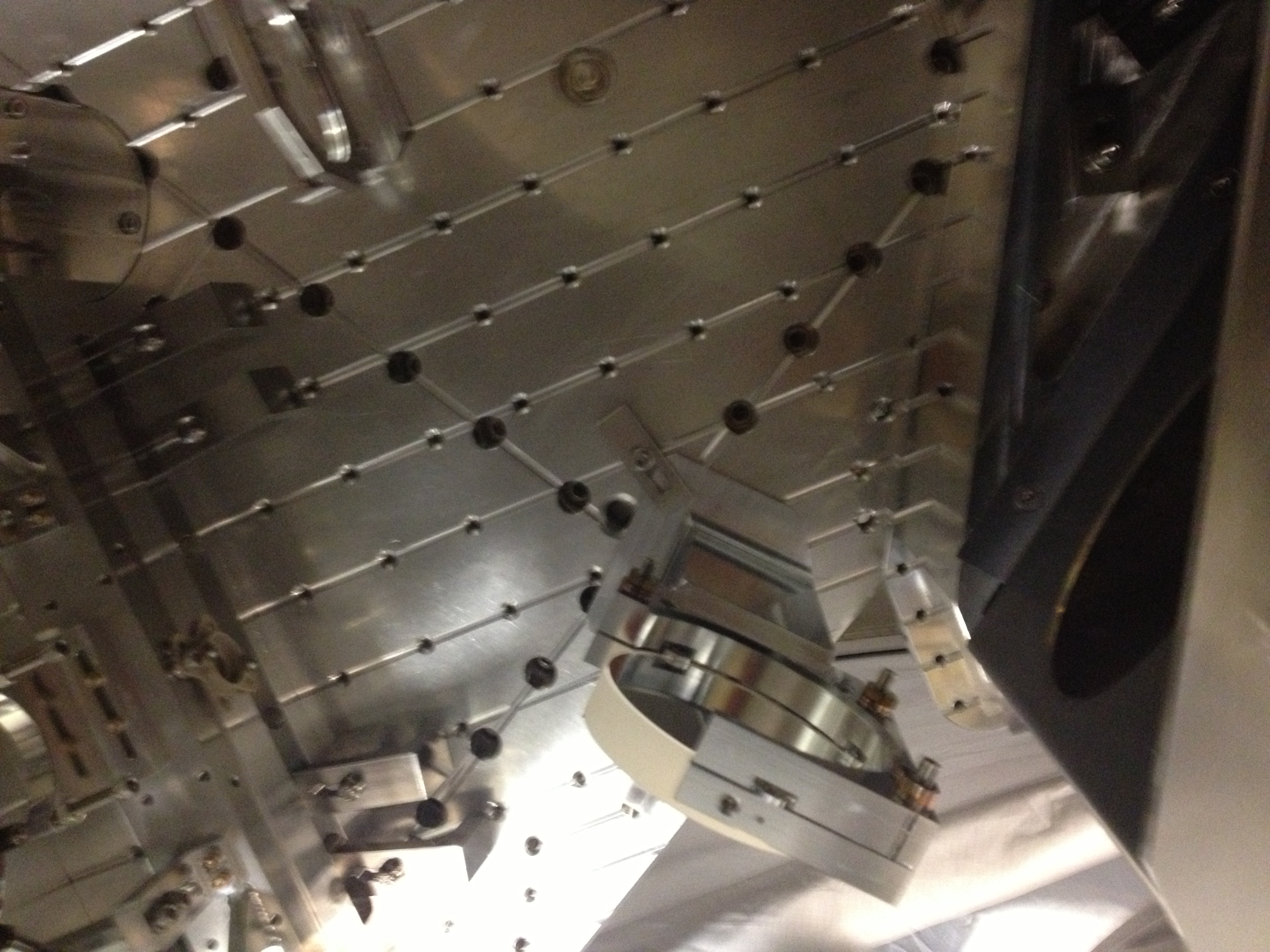
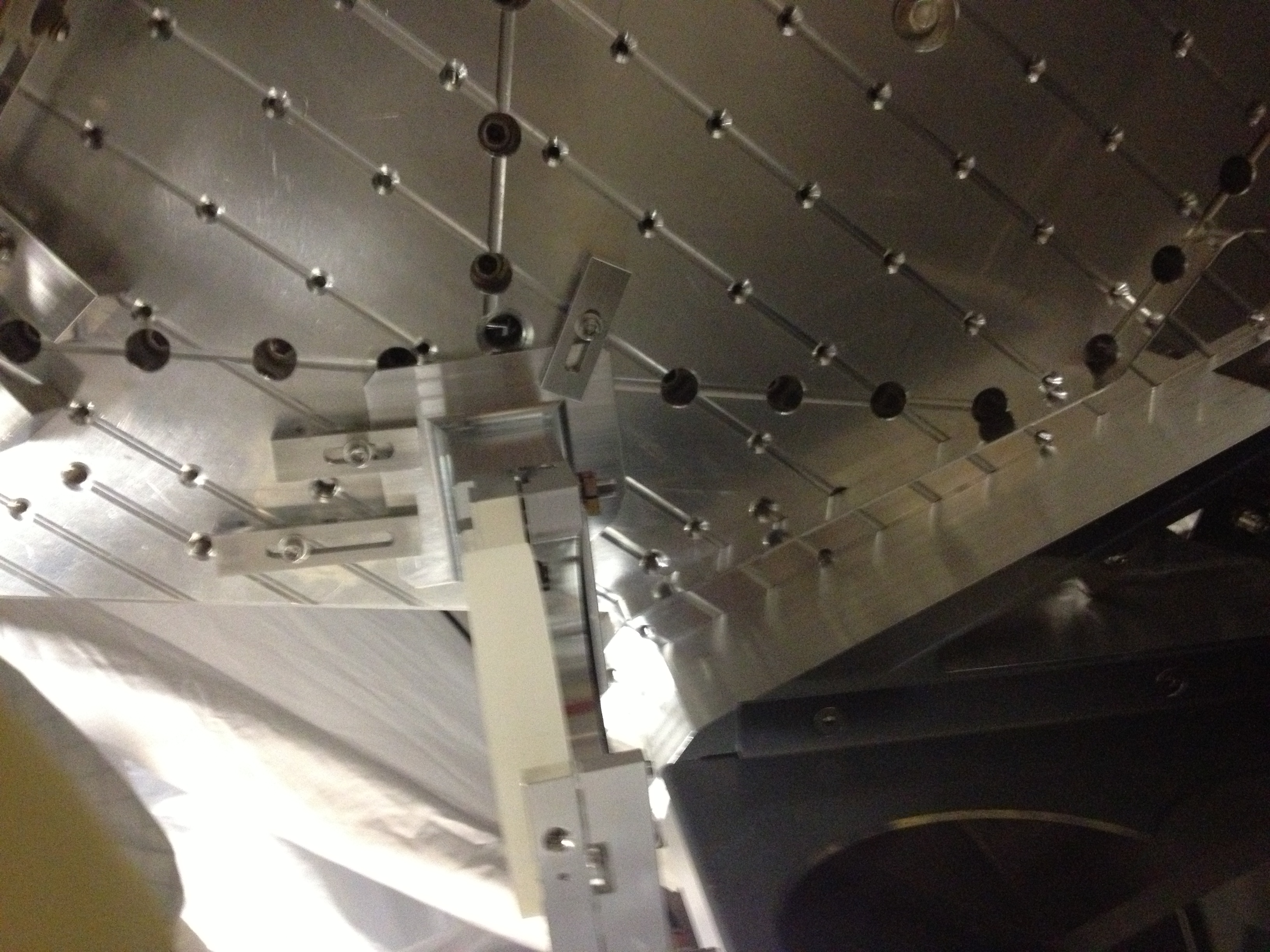
Photos of the optics are attached. We took several shots of HWSX STEER M1 and HWSX STEER M2 as these optics were moved from what is shown in the H1 HAM4 assembly drawing.