Matt H, Aidan B, Thomas V, Jason, Apollo
Okay so we jinxed ourselves when we said..okay this should only take a couple hours. We have run into multiple problems. Here we go...I am going to have some fun with this just to lighten the mood:
SR2
As reported in a previous alog SR2 had its first contact layer on the HR surface. Okay no big deal as it had its peek tab on it so simply locked the optic, and with the top gun ioniser in hand, removed the first contact (left a little of the alignment layer behind :-(..but we can get that when we re-first contact), unlocked the optic and that suspension ready (Note: ISI unlocked).
SR3
As also reported in a previous alog, SR3 also has its first contact layer on it. Okay so slightly bigger deal as the doors on HAM5. So Apollo kindly removed the south door and yep there is first contact on the HR surface...but no peek tab. Also the ISI is unlocked. Betsy asked me to look to see if the magnets that they thnk were knocked off the IM on SR3 are really gone. And I am sorry to say that yes the LL and UR IM magnets are gone...and I couldn't find them. I did notice the EQ stops on the top and IM stage were wwwwwaaaaaaayyyyyyyy back (optic level was at the distance we usually set it), so I am guessing these stops were potentially forgotten about. I have set what I could easily reach/see closer. Anyways so I locked the south side lockers and the front and back face stops of the optic. After gently easing myself into the chamber I then painted on the peek tab and waited.
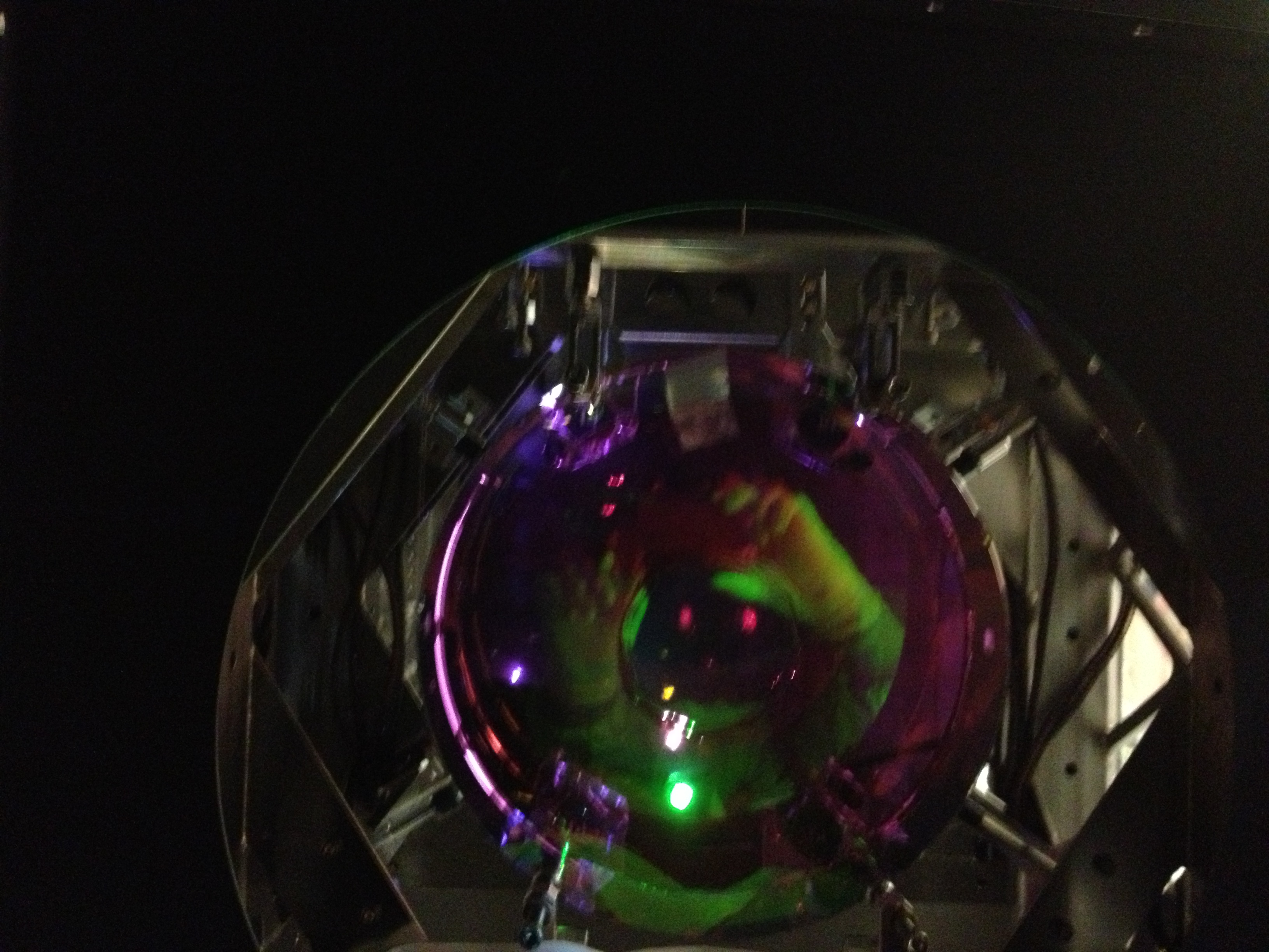
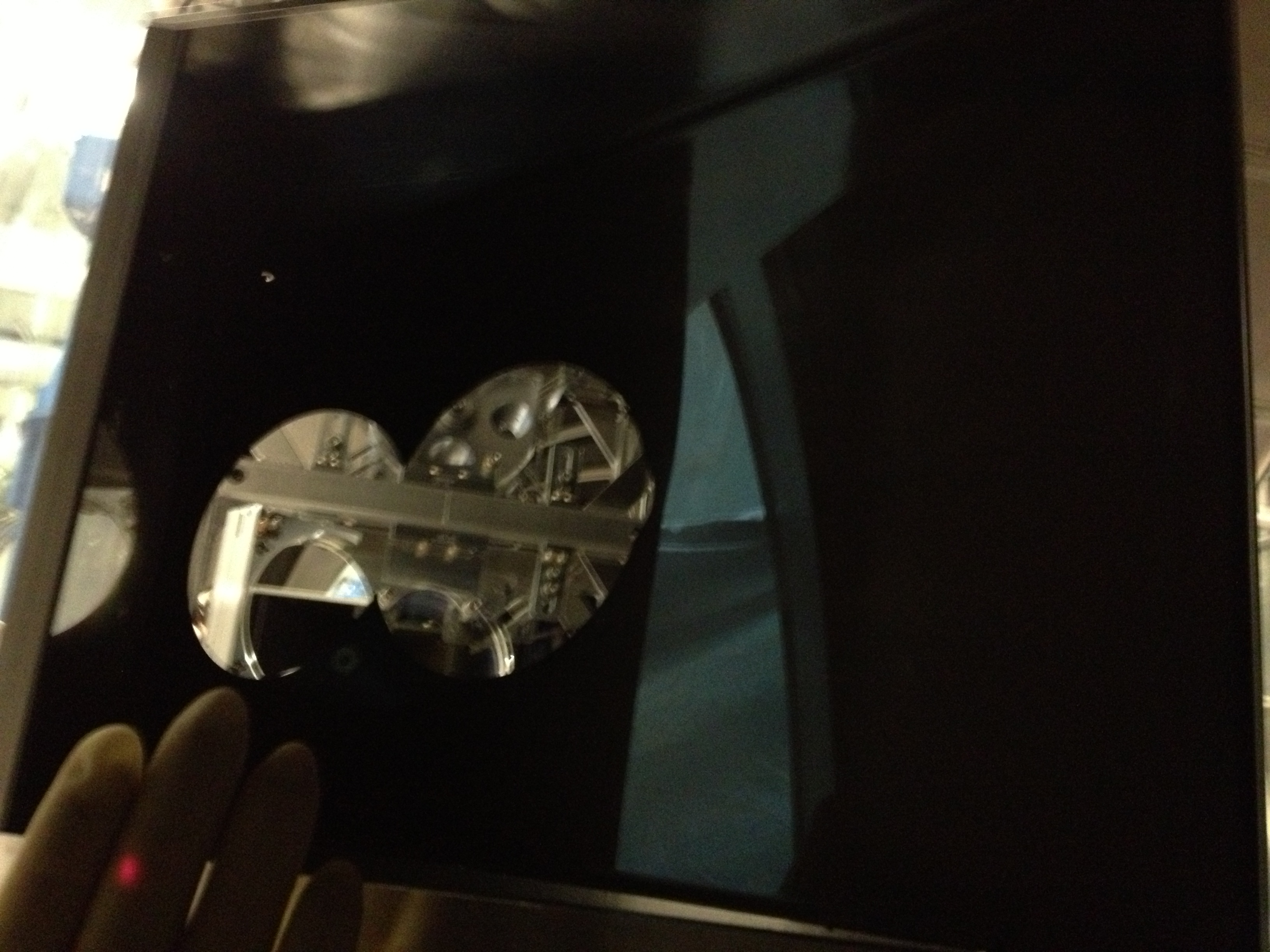
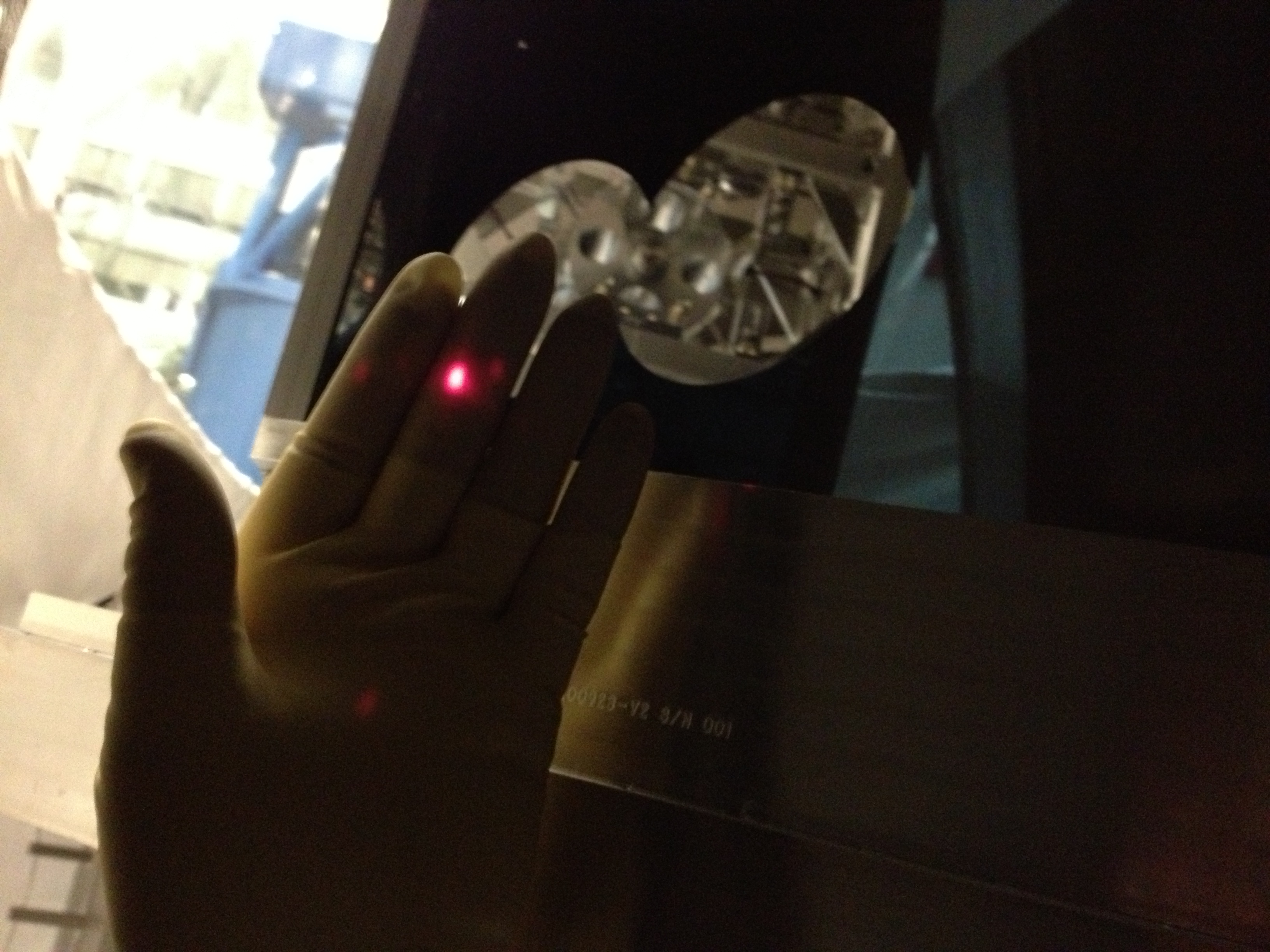
Whilst waiting for the first contact to dry we turned on the HeNe laser and first bit of good news is we see the two HeNe beams expect to see (see pic two beams). Maybe a little low though (hard to say exactly). So then pulled the FC again using the top gun (see pic peeling first contact). Looking with a flashlight there is more of the alignment layer left behind. Basically where the alignment layer met the thicker layer in a semi circle from around the 1pm position to the 5pm position. Shouldn't be in the beam path though....and again because first contacting optics again before close out should be able to get it then. I then climbed back out of chamber and unlocked first the optic of SR3 and then the ISI.
Okay so now we thought...great thats all the problems. Lets start aligning. Be done in an hour.
HAM4
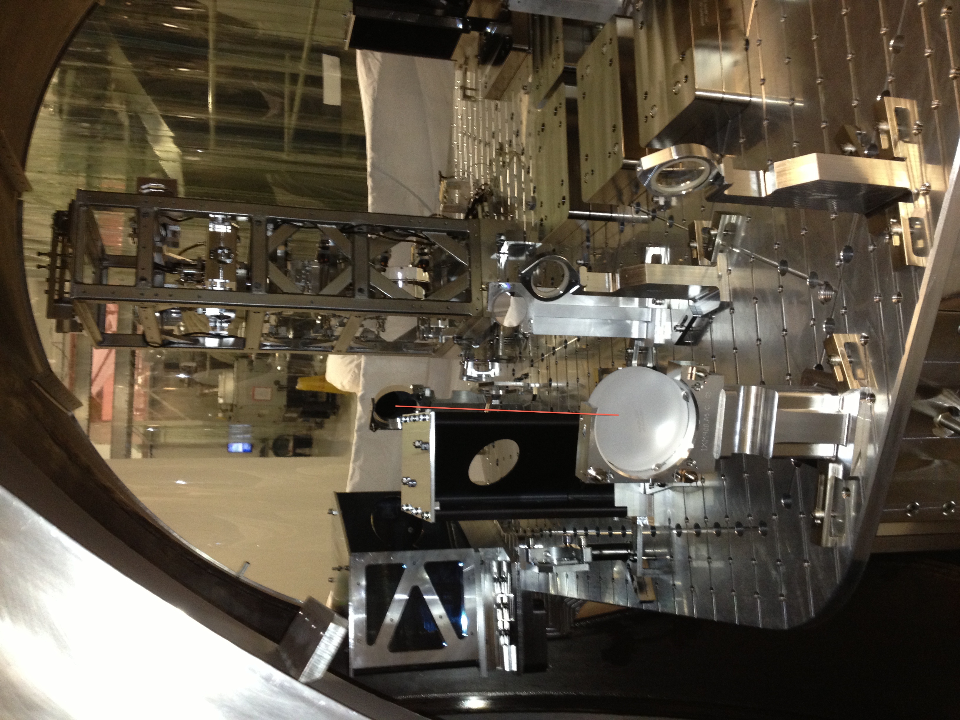
Aidan stepped up to HAM4 and it immediately was...umm guys we have a problem. The baffle doesn't line up with the beam path between two mirrors. And he was right (see pic baffle mirror out of place). The red line I have drawn shows where the beam roughly goes and that should be going through the center of the baffle. A quick check of the SYS drawings and yep everything is where it should be as per that...so somewhere along the line must of been a miscommunication.
We found an added suprise of a loose SEI rectangular mass sitting in the tube near the HAM4 ISI. Its wrapped in foil and sitting outside the chamber near the North HAM4 door at the moment
Okay so no big deal. We move a baffle or a mirror (or both) and then the ISI gets rebalanced at some stage....we can still get this done tonight.
SR3 pitch
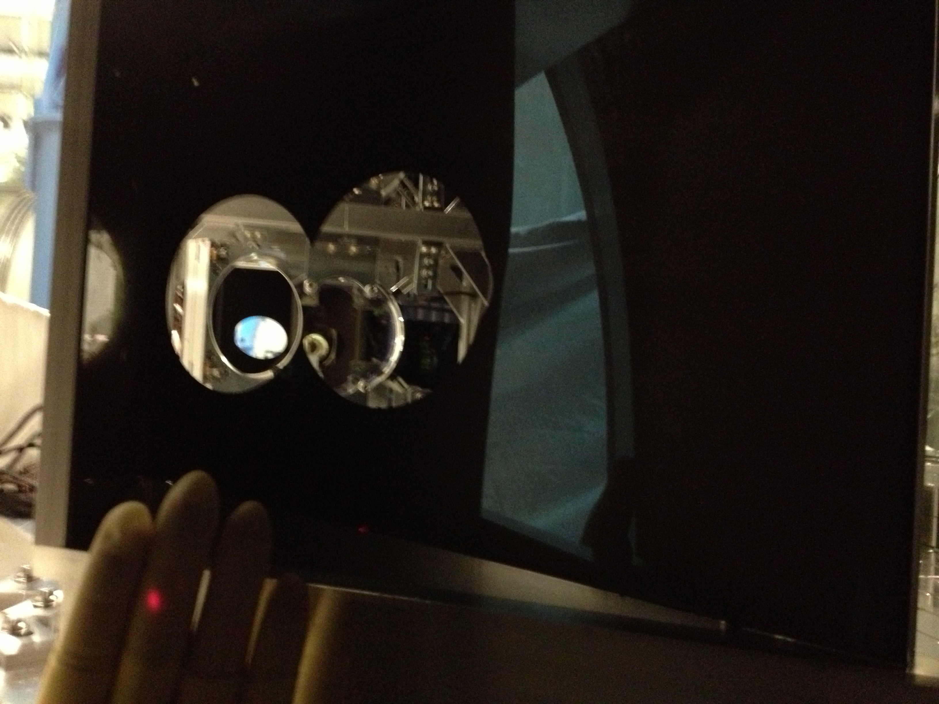
Okay so the beams bouncing off SR3 but we cant find it. So I climb back into SR2 and eventually find the beams coming back towards SR2. Unfortunately the beam looks like its 4-5 inches to low from going through the center of the baffle (see pic front reflection low). Heintze the others say..you looking at the wrong beam. No I say thats it as the back reflected beam is even lower (see pic front and back reflection). I have tried to take a better picture of just how low it is compared to where it should be (see pic beam and where it should be). It should be going through the centre of the baffle and thats 4 or 5 inches low.
So we tried pitching the optic using the BOSEMs. First off there was some queries as if the calibration is right. Can someone please quickly look at that. Then we seemed to run out of BOSEM range at around 5000 counts I think Jason said....with the beam still 1-2 inches to low on the SR2 optic. We thought maybe the suspension was grounding out on the EQ stops and I had a look and yes some of the optic ones were touching, but even after I backed them off we are still to low.
And so thats where we called it quits...without having even really officially starting the HWS alignment but having spent 6 hours on it (I do still have the south side of HAM5 ISI still locked). Jason had a look at his IAS numbers and will add a comment to this alog. So I guess we have a meeting of the minds to decide how to proceed from here.
SO much for "this will only take an hour or two"....lol. You just have to laugh in these situations............
Calum T, Eddie S, Dennis C, Aidan B, Matt H
So I think it has been discovered the problem with the mirror/baffle positions on HAM4.
Aidan double-checked the optical solution (based on the HWS optical layout coordinates in the DCC: T1100463 and T1100471). According to these coordinate sets, the two sites are supposed to be the same (except for a small variation in vertical position in the first mirror).
Looking at Sheet 2 of D1101847 (LLO) the coordinates for the 5 optics appear correct (except apparently the X-coordiante for the three last optics should be 537 not 547 (probably a typo)....but its no big deal as this just directs the beam out through the viewport).
Looking at Sheet 2 of D1101083 (LHO), the co-ordinates for HWSx Steer-M1 and HWSX Steer-M2 are incorrect.
So it appears that the baffle is correct jus tthe first two mirrors are wrong. The conclusion is that we will move these first two mirrors. There are lots of reference points (the holes) on the table so should be able to get it close. This of course will alter the balance of the ISI so will have to be rebalanced
Measured the removed FC sheets (I still had the AR sheet from when we initially aligned SR3 in April). The HR sheet weighs 1.3 g and the AR sheet also weighs 1.3 g. We aligned SR3 with the AR sheet removed and the HR sheet still on; using E1200791 this leads to a 388.7 µrad down pitch error. When we aligned SR3 I assumed the HR sheet would weigh the estimated 1.692 g stated in E1200791, which lead to the pitch correction of 505.9 µrad that was used in that alignment. This leaves a 117.2 µrad down pitch discrepancy between where we aligned SR3 to and where we should have aligned it. Bottom line here is this does not explain why we are now seeing an approximate 3.4 mrad down pitch on SR3. Will keep looking.