Advanced LIGO stochastic searches may be limited by geomagnetic fields that are correlated between sites (here). To study the possibility of subtracting out their effects on the gravitational wave channels, we have been testing sensitive magnetometers (the geomagnetic fields are mostly under a couple of pT / sqrt(Hz) around 10 Hz) and investigating sites with low local magnetic contamination: subtraction would require that we monitor the geomagnetic fields with good SNR (here).
Nelson C. procured, for evaluation, a LEMI-120 magnetometer (a similar model is used by Virgo) with a KMS-820 data acquisition unit from KMS Technologies, Houston, Texas. The KMS unit was very robust, reliable, and the software user-friendly: not a single data set, even in harsh conditions, was lost. The KMS system noise floor is under the LEMI-120 floor of about 0.01 pT/sqrt(Hz) at 10 Hz.
In order to find good sites, away from people and far from transmission lines, we used transmission line maps from BPA, and Google satellite images. Figure 1 shows the locations we selected for magnetic field measurements, which include our own vault on the LHO site because of the ease of installation and maintenance. To zoom in on a site and switch to satellite view, you can bring up my Google map by entering the following into Google Maps search: https://maps.google.com/maps/ms?authuser=0&vps=2&hl=en&ie=UTF8&msa=0&output=kml&msid=214673919740447019408.0004fc5c3f61ab108b5f5
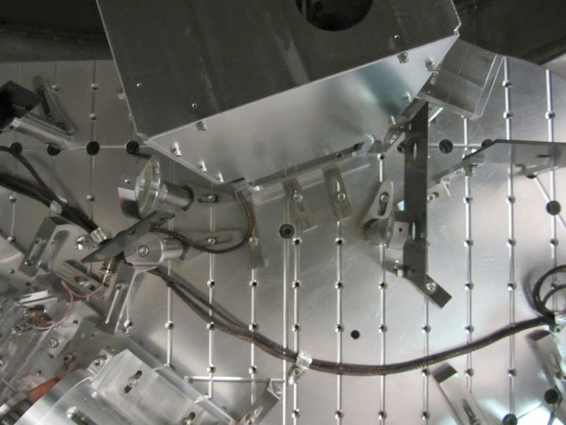
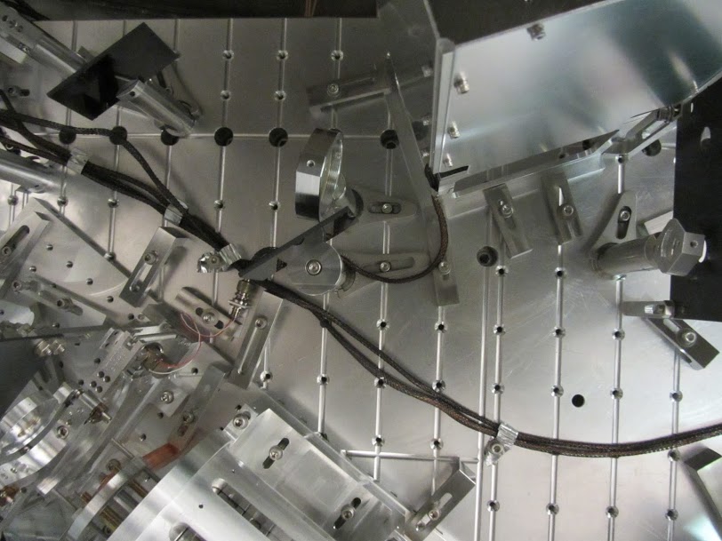
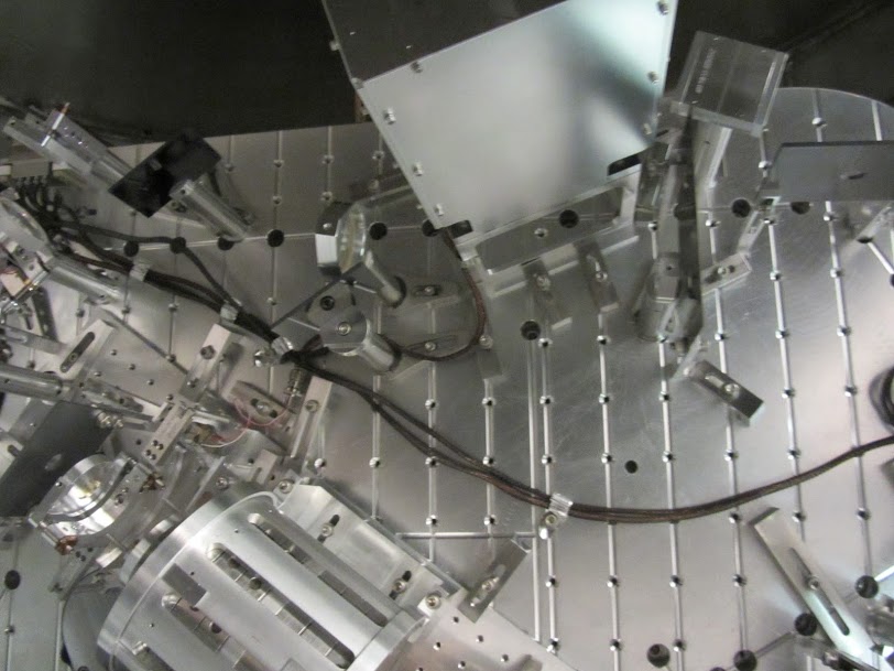
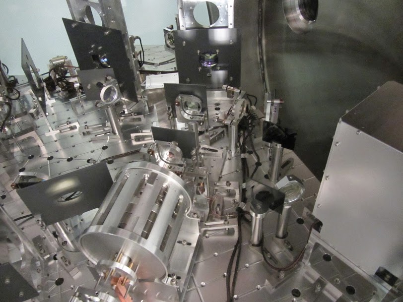
Figure 2 shows photographs of the sites. The magnetometer is buried to reduce artifacts from motion in the earth’s field. Figure 3 shows spectra. In terms of low background noise the best site was Table Mountain (National Forest) at 180 km, followed by Drumheller Channels (US Fish and Wildlife) at 56 km, followed by our own on-site vault. Rattlesnake Mountain was no better than the vault.
The longest data sets were taken at the quietest site, Table Mountain: a NS dataset of about 1 hour and an EW set of about 2 hours and 40 minutes. Also a test was made of whether fields from the data acquisition system were being detected was made by moving the acquisition system from 17 m to 8 m and 3 m. No difference between 17 m and 8 m spectra is evident, but there seems to be some contamination in the 3 m spectrum (Figure 4); All other data sets were taken with the acquisition system at 17m or more.
Also, a test of the effect of motion of field perturbing materials was made by waving a shovel at 17m at about 0.5 Hz (Figure 5), the effect was significant, but we made every effort to minimize motion for the rest of the data sets, and, in any case, transients would show up in comparisons of multiple spectra taken with the same conditions.
Pretty much all spectra in Figure 3, except for the one from my office, show lightning driven Schumann resonances (at the ~8Hz fundamental, associated with light propagation time around the earth, and above), but with SNRs that are worse for locations with larger 60 Hz signals. It will be interesting to model how well subtraction could work with an easily installed vault magnetometer vs. a more remote site.
The high-resolution spectra at the end of Figure 3 show a large resonance at about 0.01 Hz that is consistent with Pc4 band Ultra Low Frequency waves from magnetohydrodynamic waves in the magnetosphere, a frequency band associated with resonant azimuthal waves driven by the vertical E x B drift of ions bouncing between the magnetic mirrors at the poles (e.g. here).
Robert Schofield, Christina Daniel, Margarita Vidreo