sheila.dwyer@LIGO.ORG - posted 13:33, Tuesday 27 May 2014 (12088)
BS ISI tripped
This could have been due to signals from the LSC which were msitakenly sent to the BS suspension, I'm not sure.
This could have been due to signals from the LSC which were msitakenly sent to the BS suspension, I'm not sure.
This morning, I:
- added the SR3 and SRM baffles to the HAM5 table and all of their dog clamps - I don't know why I didn't anticipate that the AOS cookie cutters for these were incorrect since I just went through this at HAM4, but they are. This time, I set all of the baffles in place according to the hole pattern on the table and the maps. I will get the cookie cutters modified to be correct, but at least the weight is on the table and roughly in the correct place.
- switched out the TFE stops on the SR3 - this was more involved than I anticipated since the 2" all metal/TFE stops were trapped by their own EQ stop bracket (chalk that one up to another #facepalm #poordesign). I ended up having to dissassemble the brackets somewhat in order to rotate them to get the old and new EQ stops to clear. We shoulda done this before putting it i the chamber - put the TFE was so nice during the move...
- added a vertical 3" wafer holder and a 1" horizontal witness plate holder to the table
- added the temperature cable and it's 8 brackets to the table - I did not lace the cable since there is still an open question on how I can do this better this time. It's bundled out of the way and is of negligable weight for SEI rebalancing.
- finished securing the cable routing.
- removed all tools/pans.
So, all payload is on the table and I've turned it over to SEI for balanceing/testing.
10:08 PDT, rebooted h1guardian0 due to memory swapping. All guardian processes started automatically.
HughR, HugoP,
We installed the rencently-designed HAM-HEPI generic position loops on HAM4 last Friday. We had tried in the past but there was an issue with the way they were saved as a .mat file, before being loaded by the commissioning scripts. This has been fixed, and the updated controllers, and scripts are available under the SVN:
Generic Position Loops:
/ligo/svncommon/SeiSVN/seismic/HEPI/Common/Generic_Pos_Loops/Position_Loops/HAM_HEPI_Generic_Position_Loops_23_May_2014.mat
Plots:
/ligo/svncommon/SeiSVN/seismic/HEPI/Common/Generic_Pos_Loops/Plots/
Design Scripts:
/ligo/svncommon/SeiSVN/seismic/HEPI/Common/Generic_Pos_Loops/Scripts/
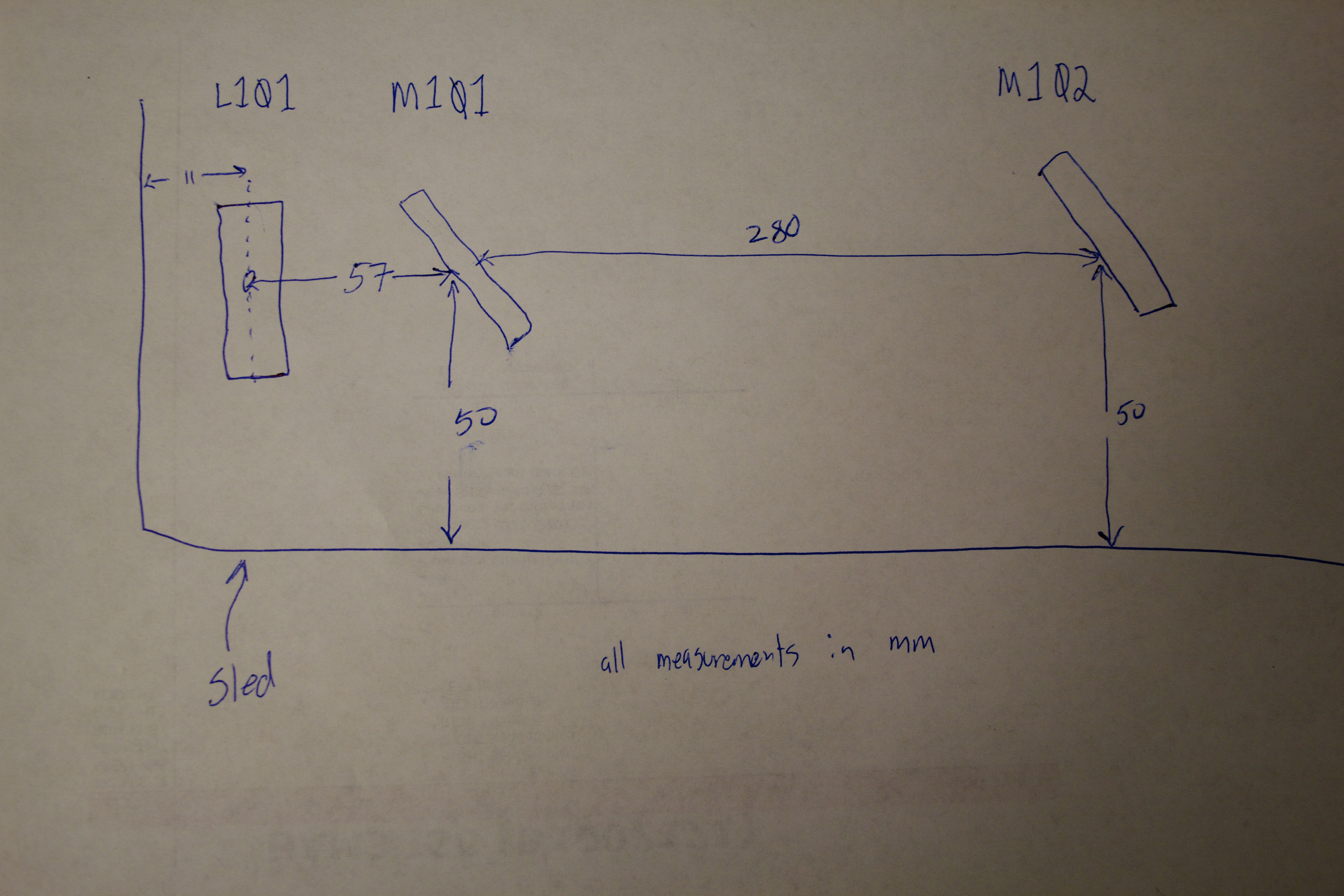
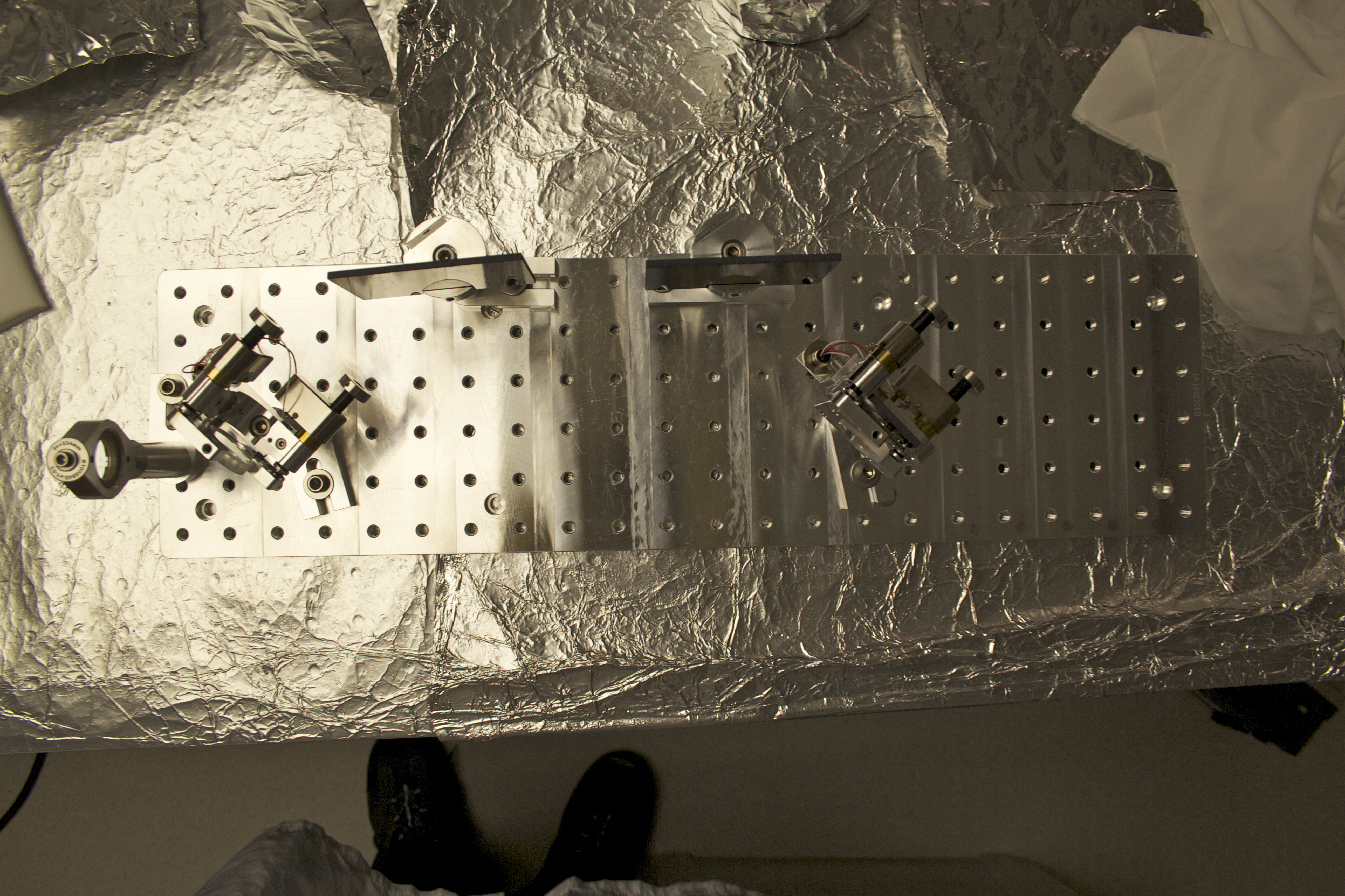
This Sled is trivial in that it only has one lens & the WFS are not on the Sled (already on table). So basically, one just lays the optics out according to the drawing; this was done months ago. Unfortunately, I didn't take photos of the layout or measure distances between optics; I opened up the Sled and did this the other day.
Photos for the Sled are here.
For the positions of the optics, I used a ruler and measured from the edge of the Breadboard to each individual optic. So, we have:
All of these measurements are +/- 1mm. (see attached photo for rough drawing of layout).
Found the DTS frame writer had a kernel panic, and the ldas gw was frozen. It's still down, and likely will be until this afternoon.
The upgrade of framecpp to ldas-tools-1.19.32 done on May 2 prevents daqd from starting, as the version of libframecpp that daqd requires is not present any longer. I'll have to recompile the daqd processes for the data concentrator, nds, and frame writer computers.
The daqd programs have been recompiled from the trunk, and daqd has been restarted on x1fw1, x1nds1, and x1dc0.
- Arnaud Pele took transfer functions on HAM5 and they look good.
- Apollo looking to tack both doors on HAM4
- CPB build preparation in the west bay cleanroom (the room w/o the solid stack)
- TCS continuing to work on HWS camera build, nominal laser hazard time in the afternoon for CO2Y alignment
- Peter King is still working on the ISS

Maintenance day today
- Water is back on!
- LN delivery to CP2
- Greg Grabeel is flushing LN2 for long term storage.
Lisa, Daniel, Sheila
The messages:
1. We could successfully engage WFS after we aligned the cavity and centered them, using Keit'a matrix
2. We don't see any improvement in the ALS COMM noise as measured by transmitted IR with WFS on and off. However, the noise is small to start with (around 10Hz rms). So we reached level 2 on Valera's levels of awesomeness (It worked, but it didn't improve the noise).
(Lisa, Sheila, Daniel)
We finally added the CM summing node to the common mode path. The signals are hooked-up as follows:
Fast readbacks still need to be tested. The medm screen can be accessed from the ALS overview screen.
I just noticed that the h1guardian0 machine is in need of some attention. It currently is using all its RAM and is swapping from disk, so presumably it is now performance limited.
The memory usage started increasing around 17:30 PDT Thursday 22nd, and got steadily worse. Swapping started at 03:30 PDT Friday 23rd and has been doing so ever since then.
We will most probably reboot during tomorrow's maintenance.
controls@h1guardian0:~ 1$ free -g
total used free shared buffers cached
Mem: 11 11 0 0 0 0
-/+ buffers/cache: 11 0
Swap: 11 5 6
model restarts logged for Sat 24/May/2014
2014_05_24 06:44 h1fw0
model restarts logged for Sun 25/May/2014
Unexpected restart of h1fw0, no restarts reported for Sunday.
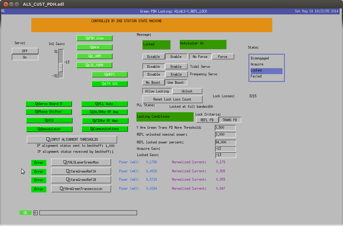
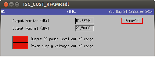
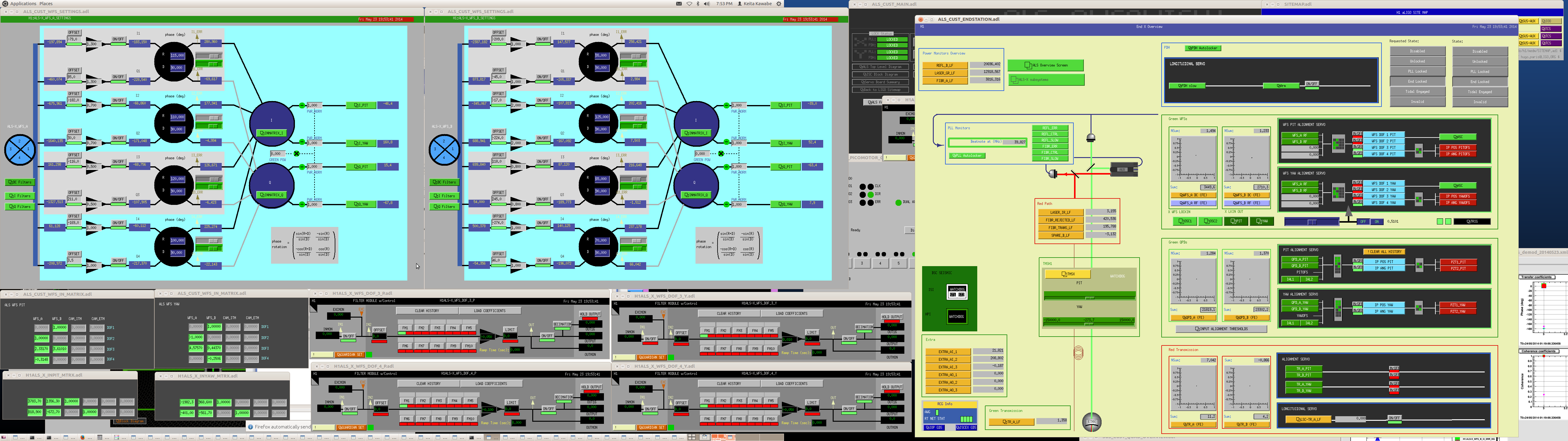
J. Kissel, A. Staley

As suspected, the problem appears to be the 71 MHz local oscillator that the Y end. At the remote advice of Alexa, I increased the ALSY's "LO mon" value, H1:ALS-Y_REFL_A_DEMOD_LONOM, from 20 to 21. As soon as I did so, the arm locked up instantly, the demod error disappeared, and the guardian error message cleared. Even more strange, the monitor value, H1:ALS-Y_REFL_A_DEMOD_LOMON is still *above* 21, so the nominal must be a mean with a range not a threshold. Even more strange than that, if I decrease the nominal value back down to 20, the arm remains locked. DAH! I guess I have plenty more to learn on this system.

Anyways, the 71 MHz power supply still claims that its power supply voltages are too low, and its output monitor, H1:ISC-RF_Y_AMP71M_OUTPUTMON, says the power is 51 [dBm]. We should fix this (if its actually broken) on Tuesday.

We should also put in some effort to making the guardian subsystem messages more clear.

For now I'll continue with the LO nominal set to 21 [??]. (Though I'm surprised that Stefan's state machine doesn't prevent me from doing this...)

Also, I attach the MEDM screen chain one has to follow to get to this information.
SITEMAP > ALS tab > ALS Overview > Y Arm PDH [little black words in a silver background box] > 71MHz RF Amp

I'm leaving both the X and Y arm locked and well aligned. And will shoot for the moon again tomorrow.

Doesn't make a lot of sense to me. The PDH LO is driven the 24.4MHz source. The 71MHz is used by the VCO. It looks like the monitor cable is unplugged, or maybe the 71MHz source is down? Check the RF monitors of the VCO. Documentation actually exists. RF monitors are part of the Beckhoff system. The tolerance is ±1dBm. A 1dBm variation of the PDH LO shouldn't prevent the Y-arm from locking.
J. Kissel, L. Barsotti, D. Hoak
Hoping to make a measurement of the length actuation force coefficient for the ETMY ESD, we tried to lock the Y-Arm using ALS. We've failed, and we don't know why. Below I outline our debugging process, but it's really not that interesting since we never found a culprit. Our best guess is something wrong with in analog at the Y-End PDH demodulator's local oscillator, because
- when we request the Guardian to changed to "LOCKED_NO_SLOW," it immediately faults out with a rather unhelpful "PDH" error message.
- H1:ALS-Y_REFL_LOCK_ERROR_MSG on the PDH overview screen claims "demodulator"
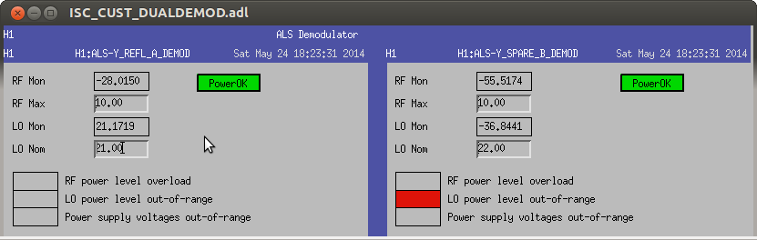
- DEMODs complain of an error message "LO power level out-of-range" for both the "REFL" and "SPARE," where the nominal values are 20 and 22 [??], respectively and the monitored values show ~ 21.2 and ~ -36.9 [??]. Dunno what units these are in. Maybe dBm?
- Opening the 71 MHz RF AMP screen, there are errors shown "Output RF power level out-of-range" and "Power supply voltages out-of-range" with a nominal value of 20.5 [dBm], and a monitor value of 51.9 [dBm].
X-Arm remains happily locked, and even survived a the big earthquake that took out the Y-ARM.
Merp.
- Found no light or flashes on ALS Y GIG-E camera monitoring the transmitted light.
- Found all Y-arm ISIs tripped (probably because of an earthquake -13 hours ago, but strange that it didn't affect X-arm. Did look that hard.)
- Found ISI subordinate Guardians not responsive because a ca.get request for the master switch had faulted out.
- Reloaded all sub-ordinate Guardians, restored them in managed mode
- Reset Y-arm ISI watchdogs. Erred out because it "filters are not in expected stated," or something like that.
- Reloaded manager, switched requested state to OFFLINE to start everyone over
- Reloaded subordinates again, set to managed, requested FULLY_ISOLATED, and things came up -- slowly, but surely -- included HEPI realignment.
- Found SUS ITMY PUM WD tripped, which forced Guardian to go to safe, with the master switch OFF, and therefore no alignment biases.
- Reset SUS ITMY WD, waited for guardian to turn everything back on. As soon as alignment sliders came on, we began to get transmission flashes on the GIG-E camera.
Since flashes, we've gotten no where. As mentioned above, the ALSY Guardian immediately faults.
- Tried tweaking alignment, because we thought transmission flashes were below locking trigger threshold. Tweaked up alignment, got normalized transmission up past 1.0, still no dice.
- Looked at optical levers after ISIs settled, there's slightly higher motion than the X-ARM, but nothing outrageous -- at MOST 0.2 [urad]_{pkpk} in ITMY, but I think that's because the blend filter configuration is different between ETMY and ITMY chambers.
- The state machine is preventing us from changing any of the PDH Board configurations, but we find
- Both ALSY PDH inputs disabled -- maybe because Guardian's waiting for "PDH" to be OK?
- Error point, H1:ALS-Y_REFL_ERR_INMON shows identically zero signal.
- DEMODs complain of an error message "LO power level out-of-range" for both the "REFL" and "SPARE," where the nominal values are 20 and 22 [??], respectively and the monitored values show ~ 21.2 and ~ -36.9 [??]. Dunno what units these are in. Maybe dBm?
- Opening the F AMP screen, there are errors shown "Output RF power level out-of-range" and "Power supply voltages out-of-range" with a nominal value of 20.5 [dBm], and a monitor value of 51.9 [dBm].
- H1:ALS-Y_REFL_LOCK_ERROR_MSG on the PDH overview screen claims "demodulator"
- Similarly (but I guess less important), there are some errors in the Phase-Frequency Discriminator spare (sign wrong, and LO out of range), but I think (a) the spares don't matter, and (b) the nominal values haven't been set.
#yakshaving
No restarts reported.
(awesome compared to what we had in the past, but still only for 3 DOFs).
I started with H1:ALS-X_TR_A_LF_OUT of about 1.1, centered WFSs, engaged the servo, and it didn't work.
Then I manually aligned the arm well such that the transmission becomes 1.2-1.25, centered WFS, and it still didn't work. Since I wasn't sure if the cavity was well aligned when I measured everything before, I started from scratch.
I measured the demod phase, and the phase itself was not a disaster, but I've found that segments were totally imbalanced (I balanced them before). Fixed it such that the seg1 signal strength against length injection is matched to seg3, same thing for seg2/seg4.
Then I measured the sensing matrix again, inverted them, put them in the input matrix, and PIT DOFs started working (but YAW not).
After several rounds of enable WFSs, center WFSs, remeasure sensing matrix, I converged to a state where 2 PIT DOFs plus one YAW DOF that corresponds to PZT2 works wonderfully. Enabling 3DOFs would immediately bring the transmission up to 1.36 or so.
Lisa misaligned ETMX such that the transmission drops to 1.0-ish, we enabled the 3DOF WFS, and immediately the transmission recovered.
Don't know why the 4th DOF doesn't work but I'm leaving it as is. For now WFS is disabled, QPD centering is enabled. If you want to enable WFS, you first need to disable QPD centering by disabling the input or output of H1:ALS-X_QPD_A_PIT and such, as the WFS feedback is also added into the same PZT path and there's no convenient way to disable QPD while allowing WFS signal to be routed to PZT.
After the PSL went down, MC2 IOP watchdogs tripped this afternoon, which cascaded to HAM2/HAM3 ISIs.
It tripped because of a large ISC length control offset signal applied on the left and right osems of the top mass.
Similarly as what Jeff did on the sus WD models (cf his alog), the trigger on DC osem values in the iop models (upper path of screenshot) should be removed to avoid this kind of situations.
This could be done during the vent period in two weeks.
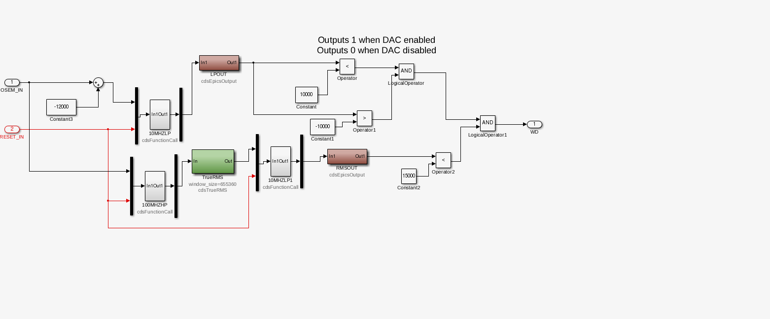
The vent period would be an excellent time for me to upgrade the IOP models to the targeted SUS/SEI watchdog system. In that system the DC component of the OSEMs is only monitored.
(Corey, Gerardo, Patrick)
Two days ago (about 4am Thurs morning) the ISS diffracted power started to drift down from about 6.7% down to 2.0%. Once at 2%, it started to go into oscillations (roughly around 3am this morning); see attached 2-day trend.
Without instructions on how to address this (and no recent alogs noting this behavior), we scratched our heads a bit, moved some gains and hit buttons to no effect. We returned back to the original state. Then Patrick suggested we try switching from PD A to PD B, and this appeared to stop the oscillations. It took us to a value of about 5%. Unfortunately, it looks like the power is still sloping down however. (Curious to see if the ISS goes back into oscillations at 9pm tonight).
Actually switching PDs was not the way to go here; we generally want to stay with PD-A.
So here, you want to adjust the REFSIGNAL (H1:PSL-ISS_REFSIGNAL) channel in 0.01 amounts. With Rick on the phone, I went from -1.63 to -1.55. This stablized the Diffracted Power and took it from ~2% up to ~10%.
