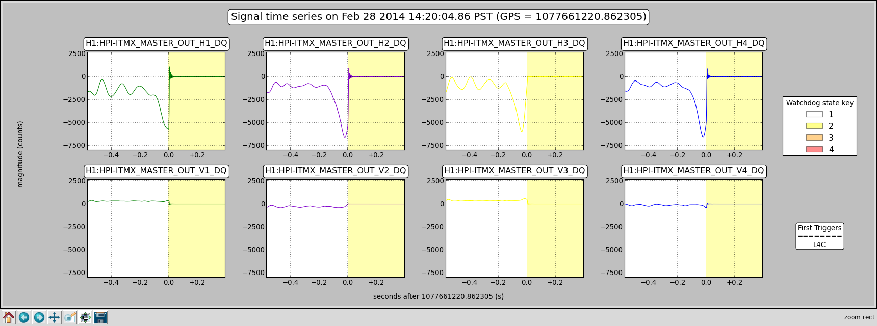
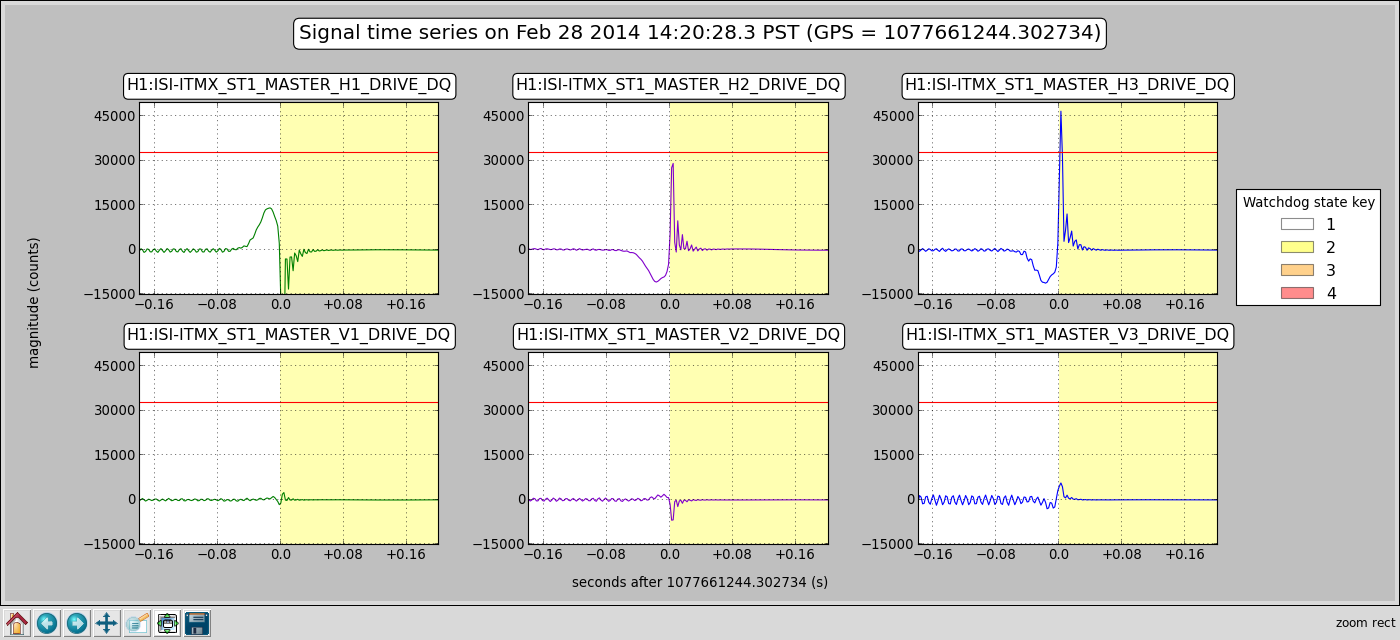
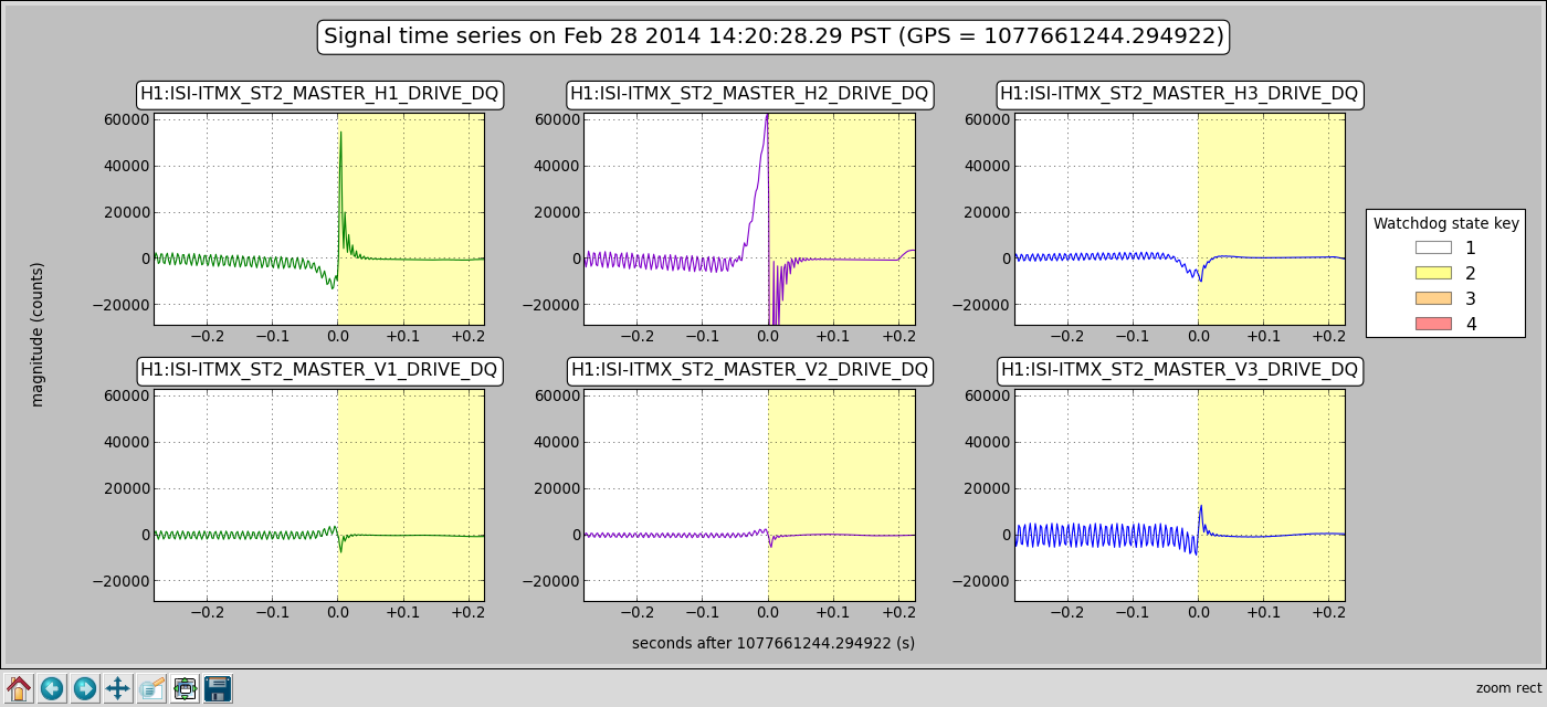
arnaud.pele@LIGO.ORG - posted 14:45, Friday 28 February 2014 (10418)
ITMX trip plots @ gps 1077661220
Images attached to this report
Kyle investigated.
Cyrus and Dave
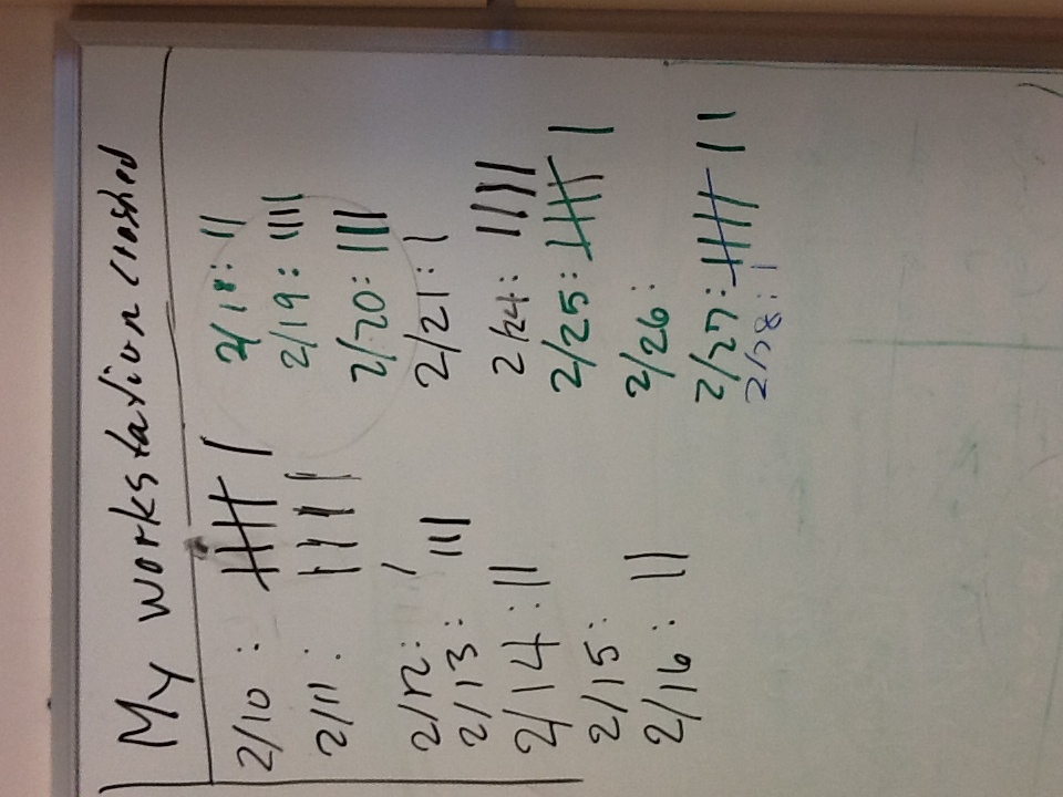
around noon the /ligo file system became unavailable, causing the workstations to freeze up. We rebooted cdsfs0 and restored the file system. We are in the process of restarting the workstations to give them a clean NFS mount.
Seconded.
(Doug, Jason, Hugh, Betsy and CO)
First look at the ETMy in chamber measurements are very encouraging.
Results:
Longitudinal was short by 0.5mm from absolute, tolerance is +/- 3.0mm,
Lateral position is 0.35mm to the south, +/- 1.00mm
Elevation position is high by 0.35mm, tolerance is +/- 1.0mm

Optic is set lightly on EQ stops, but for a first look to identify any need to move the ISI or SUS this is very reasonable results.

The arm cavity baffle was rough positioned to accommodate the line of sight from the spool and currently rests unattached on its installation table so use caution when working around it.

When fully pay loaded, cabled with the ETM suspended we will do the the fine alignments of the positions and optic angles
Forgot to mention that the particle counts were 3-4 counts on the .3 microns scale and 1-2 counts on the .5micron scale at the spool while we occupied that area.

Kudos to the folks that keep the VEA clean and well stocked with garb and cleanroom supplies.
The vertical position is actually high by 0.9 mm, not by the 0.35 mm originally stated.
J. Kissel, for F. Matichard,

As mentioned in LHO aLOG 10397, Fabrice has installed a clean set of three blend filters on ETMX, ITMX, and BS. (I loaded ITMX filters this morning). Here're plots of the new blend filters for ST1 BSC-ISIs.
"TCrappy" is exactly the same -- a version virtually identical to Ryan DeRosa's very-low-blend filters,
"Start" are an improved "750mHz" that *actually* rolls off at high-frequency and does not include the T240s.
"TStart" has the same displacement sensor / inertial sensor 750mHz crossover, but includes the T240s to get rid of L4C noise at low frequency.

The plan is to use "TCrappy" when possible, and "TStart" under high wind conditions.

7:00 pm PT EDIT:
I've now added the filters for both stages in all degrees of freedom for a BSC-ISI. I've done this using a newly committed version of
/ligo/svncommon/SeiSVN/seismic/Common/MatlabTools/plot_current_blends.m
Use it. All the time. When ever you install a new set of blends.
At 16:20:23 UTC

PSL-Status:
- Laser is on
- Output Power = 28.8 W
- Watchdog is good.
- System Status is good

PMC:
- Locked for 2 days 20 hours
- PowerRefl = 1.1  W
- PowerTran = 10.8 W

FSS:
- Locked for 1 h 12 m, relatively unstable yesterday afternoon
- Resonant Threshold = 0.7 Volts

ISS:
- Diffracted Power = 6.134%
- Last saturation event was 1h 14 mins ago.
Stefan, Kiwamu, Yuta (Yes! I have ligo.org account now!)
Last night, MC could not acquire lock after the guardian update for HAM2 and HAM3. So, Evan and I turned off the MC WFS loop and tweeked MC2 alignment offsets to lock MC. After that, we turned on the MC WFS loop and it seemed OK. H1:IMC-MC2_TRANS_SUM_OUT was ~635 and H1:IMC-IM4_TRANS_SUM_OUT was ~1600.
However, the WFS loop for MC2 was actually not turned on because the switch in the filter bank H1:SUS-MC2_M1_LOCK_(P|Y) was turned off. This was actually the cause of MC2 misalignment. Also, MC input PZTs were turned off (H1:IMC-PZT_(PIT|YAW)). So, MC WFS went crazy over night.
So this morning, we relieved the feedback for MC2 (H1:IMC-MC2_PIT|YAW) to be zero. This MC WFS relief should be added to MC guardian.
Stefan, Kiwamu
We noticed that HEPI and ISI for ITMX and ITMY had been down. So we brought them back up. We didn't investigate why they had been down.
Also, engaging the ITMX ISI was rather difficult -- we had to take out the offsets in the T240 signals by manually changing the bias targets.
Help us, Arnaud. 
The "save misalgined" command in IFO_OVERVIEW screen doesn't work for ITMX. I didn't check other suspensions. Please have a look when you have a chance.
The script align_save script running behind medm seems to work ONLY when the sitemap is opened from the terminal.
Jason and I are ready for the lateral and longitudinal ETMy position measurements in the AM. We won't know whether we will need to tweak the ACB position for any line of sight issues until the first look. Thanks Betsy and Travis for setting the ACB for us (temporary setup). We will not release the optic suspension for the fine positioning until we are satisfied that no large moves are needed.
Credit where credit is due: Mitch and Jim "installed" the ACB. Betsy and I just uncovered the SUS and mounted the corner cube.
For posterity - the ACB is sitting on the ACB "table" in the tube section between the chamber and the spool. This is to enable the IAS sighting of the ETMy optic without the ACB blocking the view while it is parked in the tube before install. We chose not to install the ACB on Stage 0 because it blocks access to the 3rd blocked side of the QUAD making alignment and sensor tuning extremely difficult. The ACB will be installed on Stage 0 after a few rounds of this is complete.
While in the chamber, we also connected the 5 SUS and 1 ring heater cables to the feedthru and confirmed signal throughput on the 5 sus. We pulled the C3 covers from both of the ETMy and TMSy suspensions before installing the corner cube.
Jason and Doug should have a clear shot of the corner cube (and probably the edges of the optic) through the ACB from the spool. We await X,Y,Z measurements.
In-vacuum ETMy SUS cable serial numbers:
Floor 1 of CB D1000225-S1104879 to D1000234-88"- 941
Floor 2 of CB D1000225-S1l04881 to D1000234-88" - 942
Floor 3 of CB D1000225-S1104882 to D1000234-88" - 940
FLoor 4 of CB D1000225-S1104880 to D1002522 - 924
Floor 1 of CB D1000225-S1104883 to RH cable
Floor 2 of CB D1000225-S1104878 to D1002522 - ? (ETMy L2 stage)
All are plugged into feedthrus on the F3 port of the chamber as per the WBSC10 D1200111 cable routing doc.
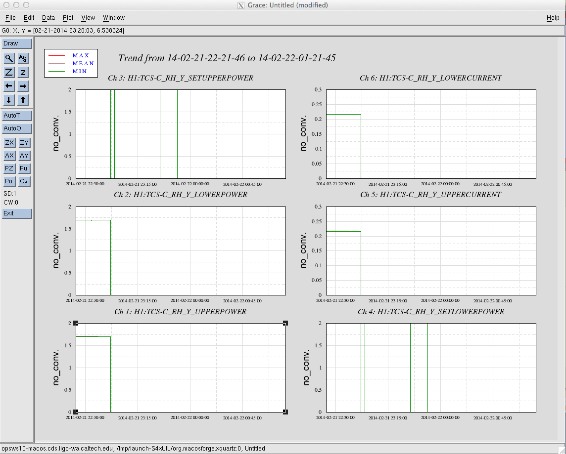
The readback channels for the corner station ring heaters seem to not have been working properly since last Friday.  I've attached a graph that shows that the ring heaters seem to have turned off at 02-21-2014 22:5:32 UTC.  Judging from the ALOG around that time, there were a lot of reboots going on in software, I'm not sure about hardware reboots.  However, Kiwamu says that the PRC power level is looking like the ring heaters are on just based off of the amount of loss he measured.  He also advised that since the system is working well, I should hold off on trying to power cycle the TCS chassis until a later time but at the first chance I get, we should try to resolve this issue.

The ITMX ring heater is also displaying similar weirdness, which is expected since they share the same chassis and PLC.
Kiwamu, Sheila, Thomas

This morning seemed to be a good time to investigate this issue.  At first we saw that the PLC3.pro was connected to EPICS but not to the System Manager, i.e. the ADC channels were not getting from the hardware to the TwinCAT software.  We tried re-running the install scripts but it did not fix the problem but it did help us figure out that there were some channels deleted recently.  Daniel let us know that if there are some additions or deletions, we should re-map the configuration before recompiling.  This solved the problem!
(Alexa, Jax, Stefan)
Alexa was trying to hunt down a missing gain factor for her model and instead found a busted COMM PLL board (serial number S1200564). The op-amp for the VCO compensation stage (U37) was blown. I recalled replacing the same op-amp on the DIFF PLL about a month ago, suggesting that there's something that makes this particular op-amp vulnerable. After discussing with Richard McCarthy, we opted to change resistor R96 from 0 to 2k ohms to protect the poor thing. Lab tests show that it's in good shape, and it'll be back to the ISC rack as soon as we're done with the ISC meeting.
Should this resistor change be propagated to all PLL boards?
No, we're still thinking about it. It's going in as modified and if it keeps having problems, we'll burn that bridge when we get to it.
This smells of an ISC integration issue so we don't forget...
