Stefan, Lisa, Kiwamu,
Our goal tonight was to lock PRMI with the 3f signals. However we didn't reach that point yet because of a (perhaps new) issue in the PRMI locking.
A good news is that the power build up was high because of the ring heater on ITMY which had been set at 4 W in total. POPAIR_B_RF18 went to 8000 counts.
40 Hz unidentified oscillation in PRMI signals:
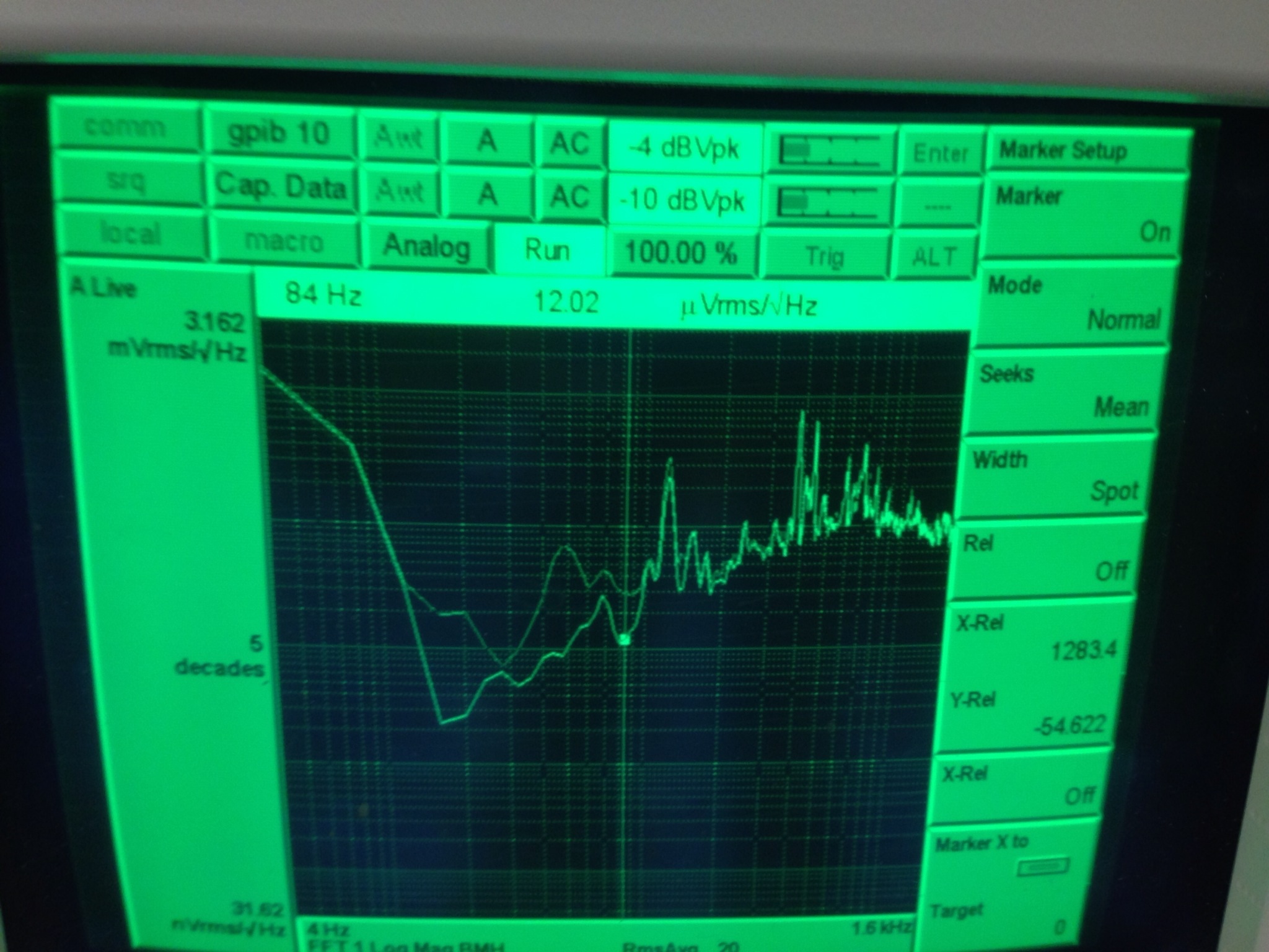
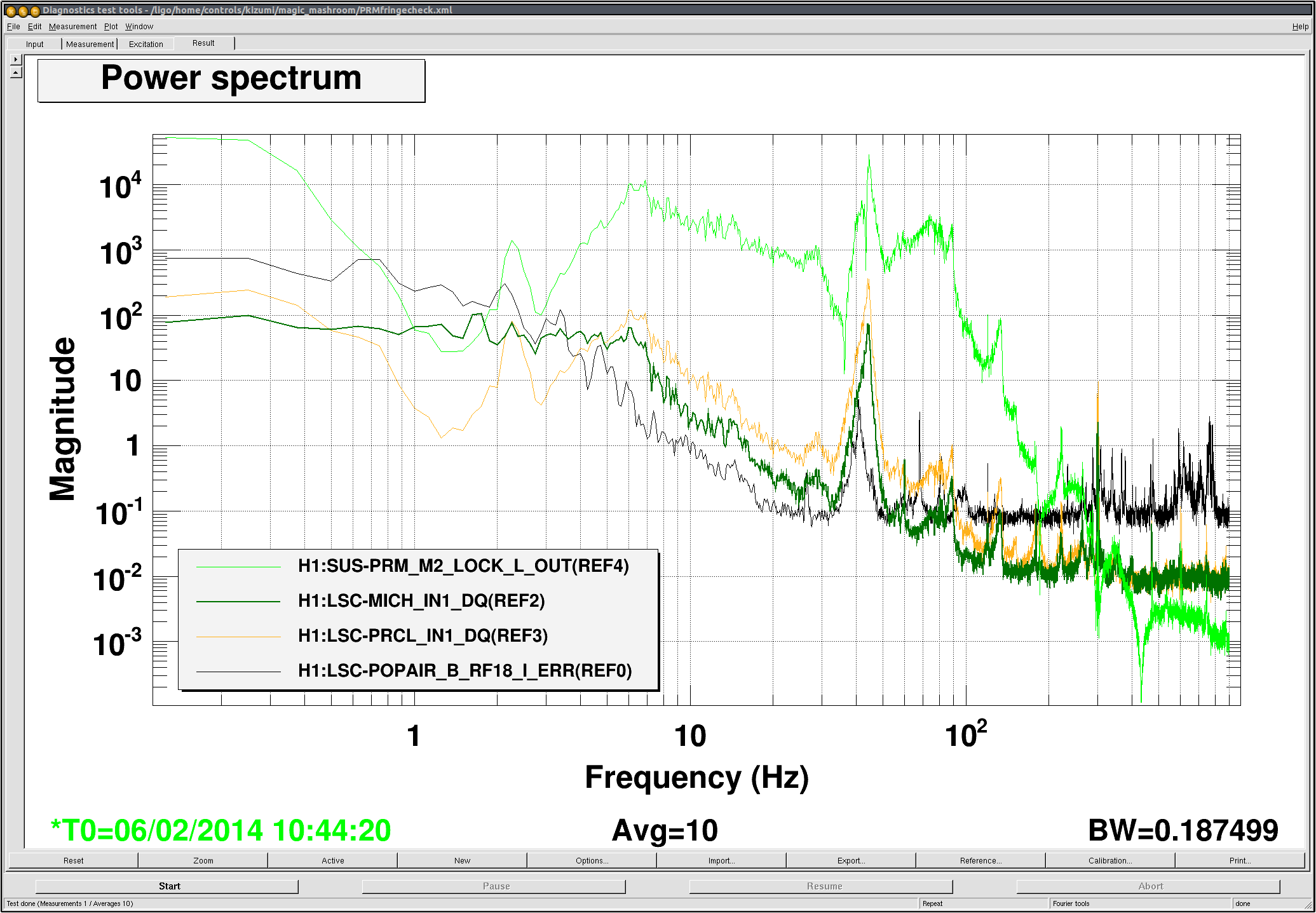
After some tweak of alignment and gains, we managed to lock PRMI with the sidebands being resonant. However the PRMI lock was fragile for some reason. In particular, it lost the lock frequently when we changed the PRC gain. We took spectra of the signals and were surpprised by a huge peak in both PRC and MICH signals. This was causing a DAC saturation in the M2 stage of PRM which made the PRC loop unstable. This is something we didn't see before. We looked at some previous spectra from the last long stretch of 3rd of February (alog 9809) and confirmed that there was no such oscillation at that time. The attached shows spectrum of various signals from tonight. It is obvious that there is a broad and prominent oscillation at around 40 Hz in each signal. Note that when I took this data, I had a notch in PRM M2 stage to mitigate the saturation and that's why the PRM_M2 signal look a bit suppressed at around 30 Hz.
We tried to lower the UGF of PRCL, but the oscillation persisted. In fact the peak moves as we changes the UGF. For example, lowering the UGF also brings the peak frequency lower. We suspected a gain peaking and tried to move the UGF, but somehow the gain margin was so narrow that we could not move around so much. According to a quick swept sine measurement, the UGF was at around 40 Hz.. Another thing we suspected was a roll mode which is usually at around 40 Hz in the case of the small triple suspension. Since we failed to lower the UGF, we could not really try a notch technique to minimize unwanted excitation. We also looked at MC_F because we suspected the roll mode of MC2, but there was no visible oscillation at all. I also quickly tried the PRX locking to see if it still persists, but I didn't see any oscillation in PRX.
We are still unable to identify this oscillation.
Some other notes:
- We turned off the isolation loop of ITMY and BS ISIs at the beginning of the PRMI commissioning tonight.
- The power recycling gain steadily kept dropping over 5 hours despite of our semi-automated alignment. See attached. I have no idea why.
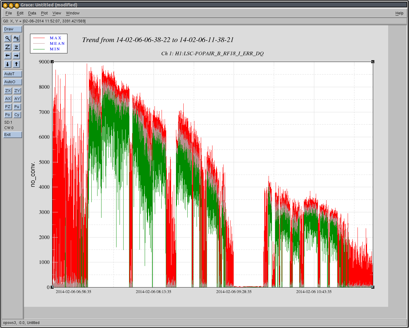


 (Also this is kind of a side track of the PRMI commissioning)