Following updates of guardian at LLO from the past few weeks, I started updating some sus guardian
New feature for saving alignment :
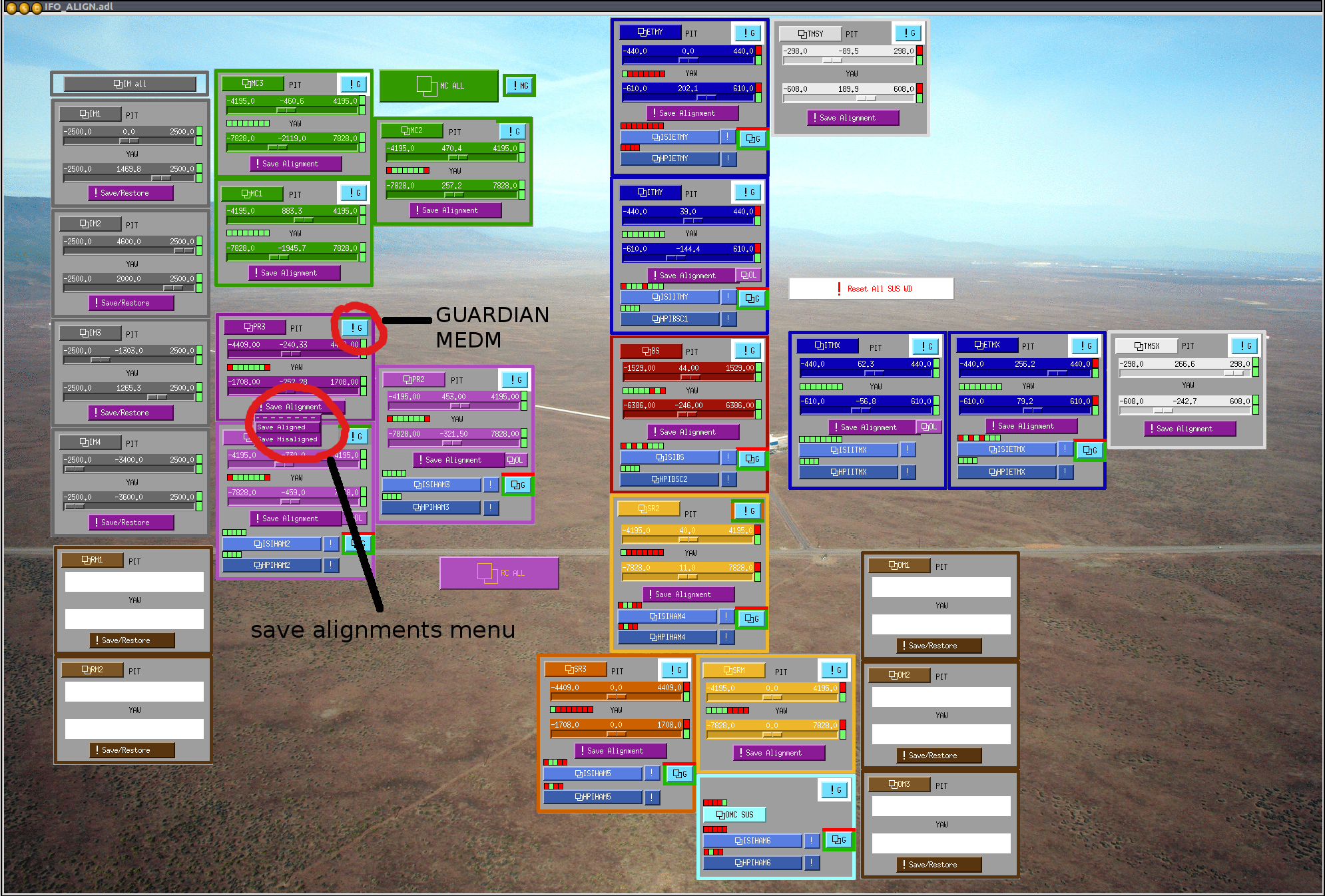
It is now possible to save the aligned as well as the misaligned position of the suspensions for every optic. This can be done through the IFO_ALIGN medm screen via the Save Alignment menu (cf IFO_ALIGN.png) or with the pyhton script align_save_burt -a -m living in /opt/rtcds/userapps/release/sus/common/scripts/
For more details see llo alog 10436 and 10466
Restoring the saved alignments :
This is done through Guardian by switching between different states of the suspension. Guardian medm screens can be accessed via the ! G buttons in the IFO_ALIGN medm screen (cf IFO_ALIGN.png).
For now, only PRM PR3 and MC2 are running under the guardian and can be restored this way. For the other suspensions, it will need to be done manually (until a guardian process is created).
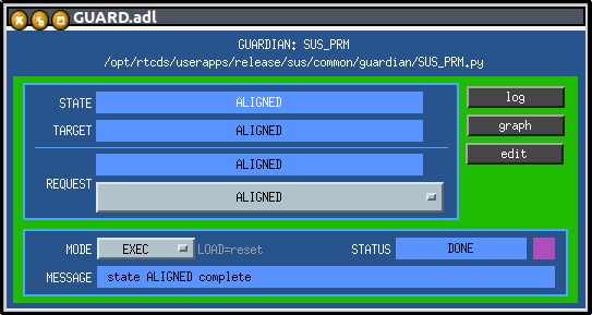
When the guardian medm screen is open, it is straightforward to switch between aligned misaligned damped or safe via the "REQUEST" menu (cf GUARD_PRM.png)
IFO_ALIGN.adl was updated from livingston but I had to make some modifications to get the links functioning. The new adl file was commited under the svn
1) As Kiwamu pointed out to me, the arguments under the Save Alignment link were in the wrong order (e.g. "align_save_burt MC1 -m" instead of "align_save_burt -m MC1"), so I modified it for MC1/MC2/MC3/PRM/PR2/PR3/SRM/SR2/SR3/BS/ETMX/ETMY/ITMX/ITMY/TMSX/TMSY
2) Also, the command to create a guardian medm screen (guardmedm) had the full llo path defined (/ligo/apps/ubuntu12/guardian/bin/guardmedm) which doesn't exist here so I changed it to guardmedm without the path. That should also work at llo.