J. Kissel
Given that this morning's ETM motion provided for difficult arm cavity locking and CARM hand-offing again, I've continued to pursue the long-term stability of the X ARM ISI Performance, by studying the ISI performance at 3 different times.
Here's what we learned (or re-learned) from the study today:
(1) Today (2014-02-13 17:00 UTC) was a really high-wind day. Yesterday (2013-02-13 04:39 UTC) was a medium-wind day. Two days ago (2014-02-12 01:00 UTC) was a low-wind day. The green team really liked two days ago, they were marginally happy with yesterday, and could not get anything done today.
(2) From Robert: "At the X-end, wind, which comes primarily from the Northwest and West and beats against the side of the building, tilting the building, slab, and ground. This motion is seen as increased signal in ground seismometers between 0.02 and 0.1 [Hz]. The corner station, being a shorter, squat building is much less sensitive to wind."
(3) In the current configuration, with Level 3 controllers and TCrappy blends, The longitudinal motion of the ETM suspension point is dominated by RY motion between 0.2 and 2 [Hz].
(4) The Level 3 controllers and TCrappy blends attempt to get awesome performance between 0.2 and 2 [Hz], because -- during low-wind days -- the QUAD pitch motion at the test mass between 0.3 and 0.7 [Hz] dominates to cavity motion. When larger than ~80-100 [nrad/rtHz] @ ~0.5 [Hz], the 0.3-0.7 [Hz] angular fluctuations make holding the optical gain constant difficult, and due to the poor quality of the coatings in green the cavity is more likely to fall out of lock.
(5) The wind / slab tilt does not obviously increase the ground seismometer signal between 0.3-0.7[Hz] band.
(6) During high-wind days, 0.02-0.1 [Hz] pitch motion of the ETM supersedes the 0.3-0.7 [Hz] motion, increasing the RMS motion so much so that the green VCO regularly saturates, kicking the cavity out of lock, again above ~100 [nrad] RMS.
(7) The TCrappy displacement sensor blend filter has a broad, factor-of-three-ish gain-peaking amplification hump between 0.01-0.07[Hz]. The filters were pretty good copies of L1's blend filters, where wind and 0.02-0.1 [Hz] motion is regularly pretty darn small. It's merely unfortunate that our ground motion is so volatile and different at these frequencies that we won't be able to use the exact same blend filters between the two IFOs.
(8) In order to reduce the cavity motion below the saturation limit of the VCO, one could try to just offload the bulk of the control authority to HEPI along the IPC tidal path up to, say a little past the microseism (but before the QUAD suspension resonances to keep the loop design simple). BUT the ISI's TCrappy filters blend at ~0.06 [Hz], with a *ton* of loop gain from the Level 3 isolation controllers, so any motion injected into HEPI will get ignored / suppressed by the ISI's inertial sensors above the blend frequency.
(9) The TCrappy blend filters we used in the design of the Level 3 controllers, and those particular blend filters are only "psuedo" complementary. Though this hasn't been thoroughly tested or confirmed, the belief that this means that TCrappy blends can *only* be used with the Level 3 controllers, and vice versa. The ISI had tripped one or two times while switching from this blend configuration to another, but there's not yet direct evidence that this marginal in-complementarity was cause.
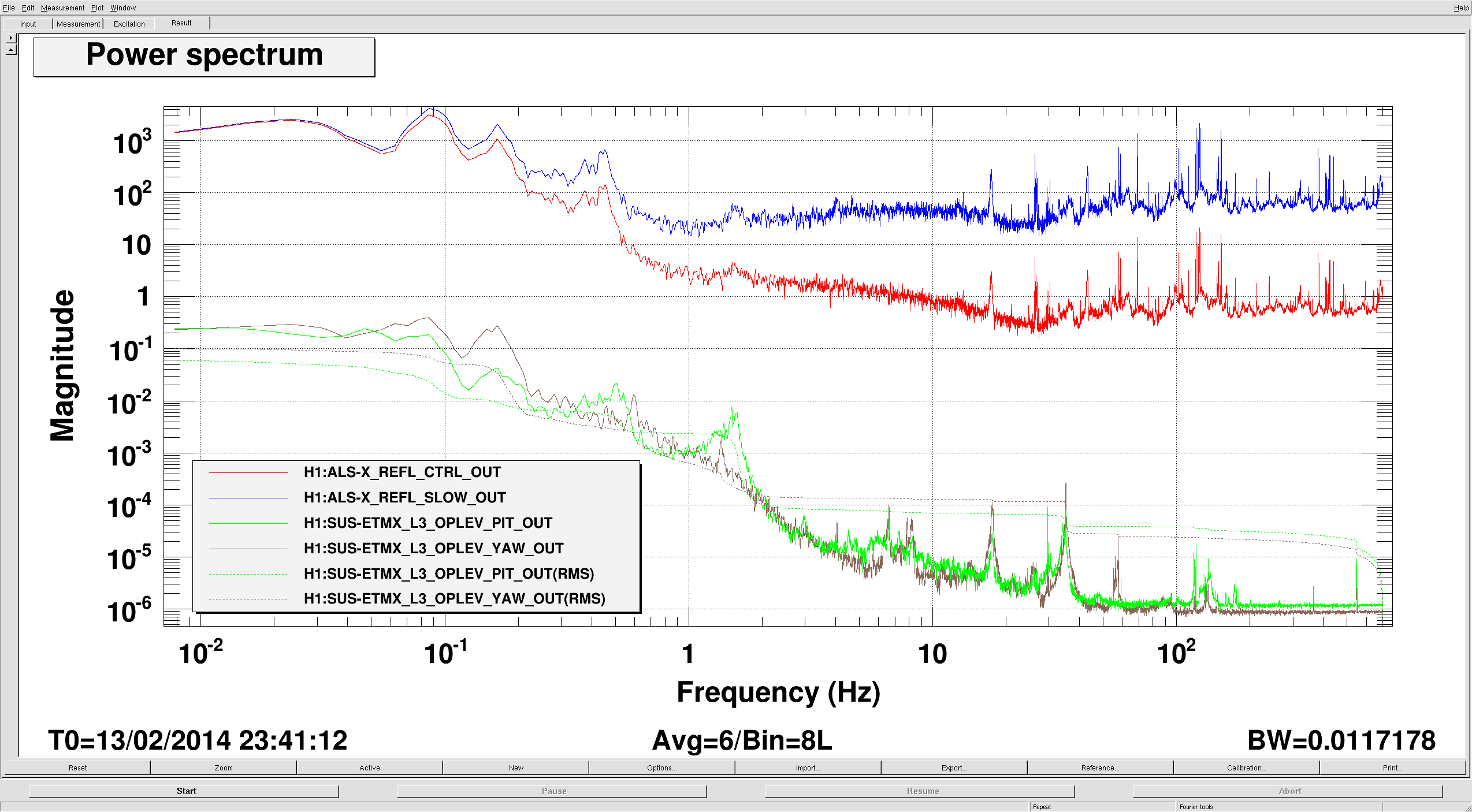
(10) The ITM is consistently performing better than the ETM, as measured by the optical lever -- but remember, it's unclear whether we can trust the short-armed ETM lever to be measuring pure pitch below ~0.5 [Hz].
(11) The ITM optical lever's signal consistently has some high-frequency fuzz on it, above 0.5 [Hz] that's clearly visible in the SUM. Stefan suggests we should investigate / replace the laser head to make sure this isn't mode hopping of an old dying diode.
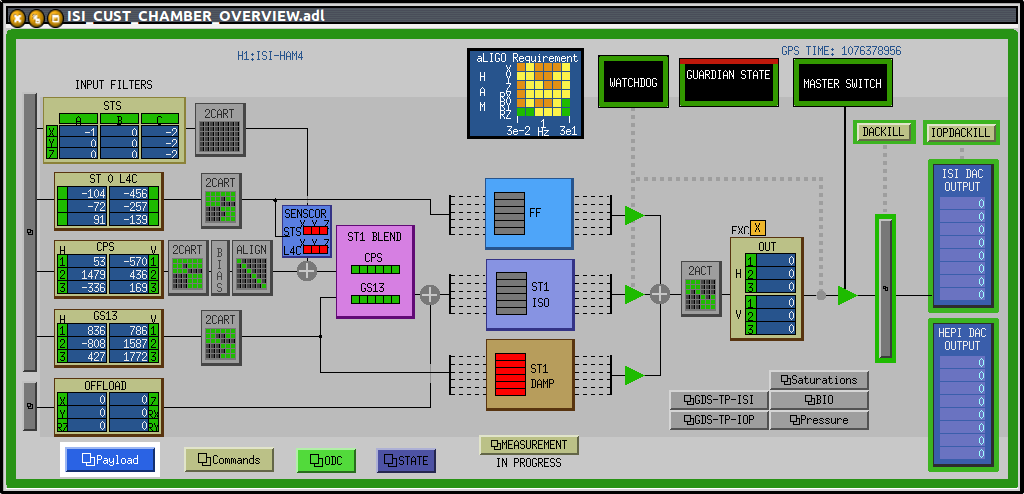
(12) One can monitor the blend filter status by watching the H1:ISI-ETMX_ST*_BLND_*_*_CUR_SWSTAT channels. At least in this case where we are using all TCrappy filters in FM5 of the filter banks, with the input, output, offset, and decimation buttons on, the bit-word is 7184.
In conclusion,
- We need to pay attention to tilt, not just the translational direction of the ISI.
- Our performance is volatile, depending on the weather, so need to consider having windy-day vs. calm-day blend filters that we regularly are able to switch between without trouble.
- We still have work to do on the ISIs. Sensor correction, which has not been commissioned on either X ARM platforms can perhaps help, but maybe not if we are blending so low. We should most certainly investigate a set of blends with less gain peak in the wind band.

(Accidentally posted this as kiwamu, sorry.)
Additionally, RFM IPC outputs for WFS DOFs have been added.
We have added outputs for the four ALS-X WFS degrees of freedom, which have been newly added to the ALS_END model (see revision 7127). These are intended to be used to feed back onto the X test masses.
We have also added a trigger input to monitor green transmission, but it is currently disabled.
This is SVN revision 7128.