In order to ensure that the ODC bits are sending valid reports, I've visually confirmed the status of each subsystem module mentioned below. The ODC is currently reporting a happily locked mode cleaner and I confirm this is true. The goodness has been going on for a while now (as Stefan and Kiwamu are trying to lock the PRMI), but officially, we can say the goodness has been on-going since Jan 21 2014 6:00pm PST (Jan 22 2014 02:00:00 UTC, GPS 1074391216).
DetChar bonus tasks:
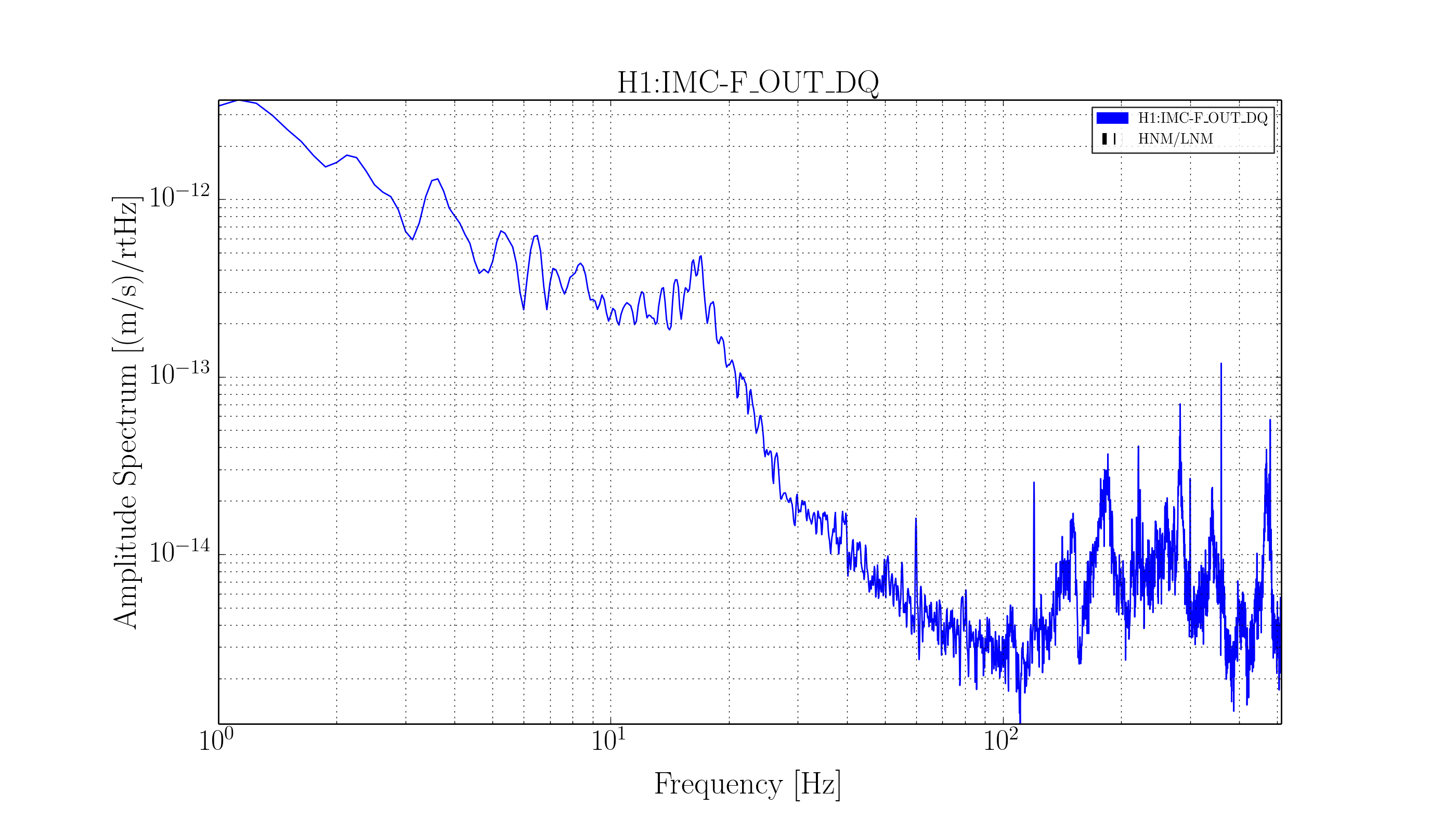
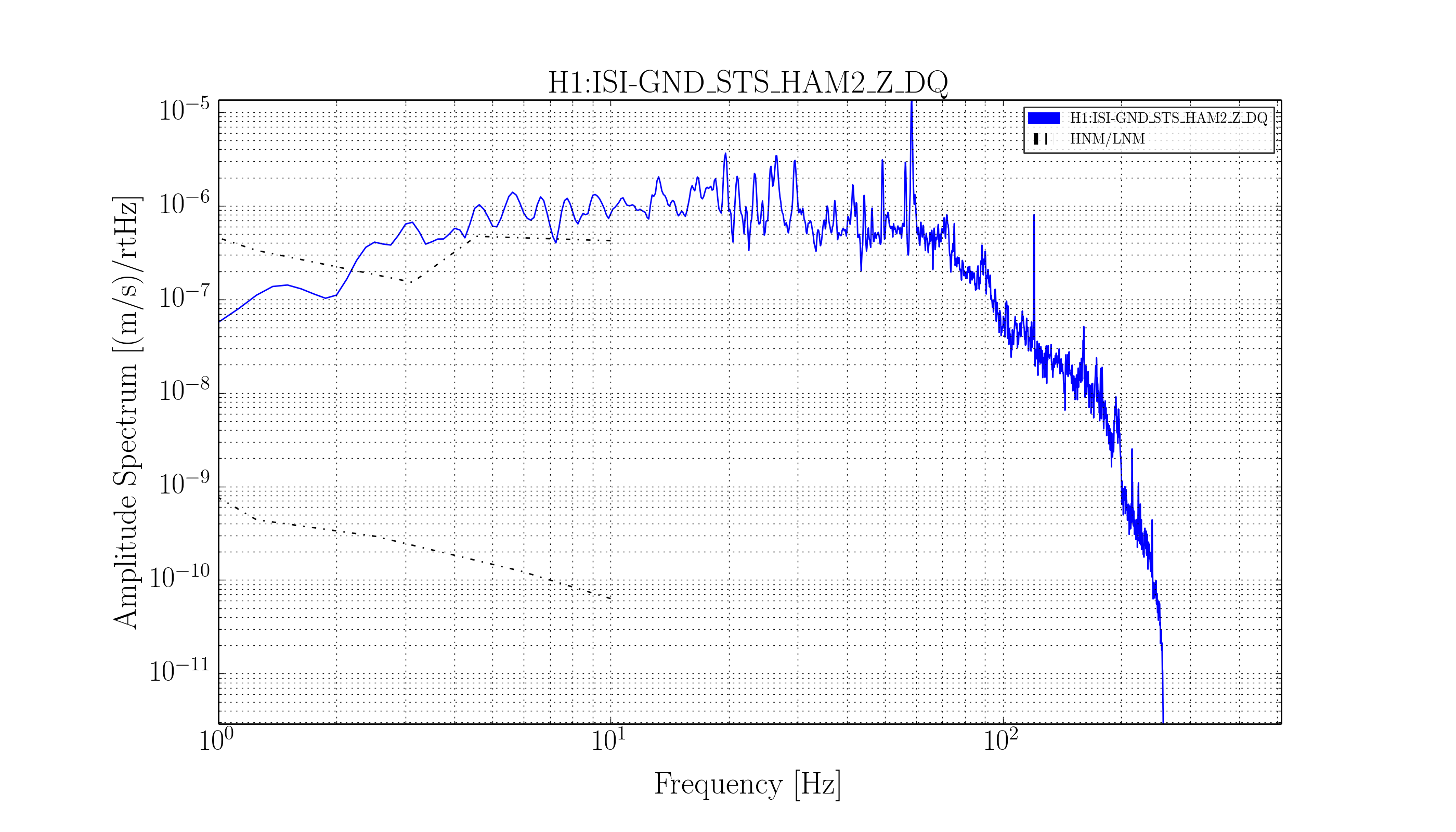
- Post performance ASDs of all the components mentioned below as a comment. I wanna see what "good" looks like for these systems.
- We should also be able to use tonight as an average reference ASD for recoloring the IMC_F / IMC_L data in to fake DARM.
- Show me spectra of the coil driver noise monitor channels. Show me what a "normal" coil output voltage ASD is for each of the driver stages. Let me know if there are any DAC saturations.
- For the IMC ODC, trend the H1:IMC-MC2_TRANS_SUM_OUTPUT, H1:IMC-IM4_TRANS_SUM_OUTPUT channels (which feed into ODC bits 10-13). Tell me where they average, and what the peak value is on the ~minute time-scale. Find out from the IO group what the expected power budget is from POWER IN to MC2 TRANS SUM, and from POWER IN to IM4 TRANS SUM, so we can stick that into the [W/W] gain and have these bits' thresholds be calibrated.
During this time there was no excitation on anything mentioned below.
IMC: IMC Locked, IMC WFS control ON, spitting out clean 00 mode light.
ODC bits all green (0-13), bits 2-9 masked out (see LHO aLOG 9373), summary bit (bit 0) and bit 10 are masked out (why?)
HAM2:
HPI: well-performing, well-aligned to target values. Level 1 isolation filters, position-sensor-only ("Pos") blend filters.
ODC bits all green (0-3), but summary bit (bit 0) is masked out (why?).
ISI: well-performing [BLRMS lights are mostly green, with some yellow in upper-left corner], well-aligned to target values. Level 3 isolation filters, with "01_28" blend filters.
ODC bits all green (0-4), but summary bit (bit 0) is masked out (why?).
MC1: IMC locked, IMC WFS control ON, locally damped and aligned
ODC bits all green (0-7) are green, but summary bit (bit 0) is masked out (why?).
MC3: IMC locked, IMC WFS control ON, locally damped and aligned
ODC bits all green (0-7) are green, but summary bit (bit 0) is masked out (why?).
HAM3:
HPI: well-performing, well-aligned to target values. Level 1 isolation filters, position-sensor-only ("Pos") blend filters.
ODC bits all green (0-3), but summary bit (bit 0) is masked out (why?).
ISI: well-performing [BLRMS lights are mostly green, with some yellow in upper-left corner], well-aligned to target values. Level 3 isolation filters, with "01_28" blend filters.
ODC bits all green (0-4), but summary bit (bit 0) is masked out (why?).
MC2: IMC locked, IMC WFS control ON, locally damped and aligned
ODC bits all green (0-7) are green, but summary bit (bit 0) is masked out (why?).
I don't imagine I'll get the chance tonight, but if possible I may put these components in various *bad* states tomorrow, to check that the ODC properly reports as such.