Heavy snow onsite – arms drivable with caution
PSL enclosure in Science Mode. LVEA in laser SAFE.
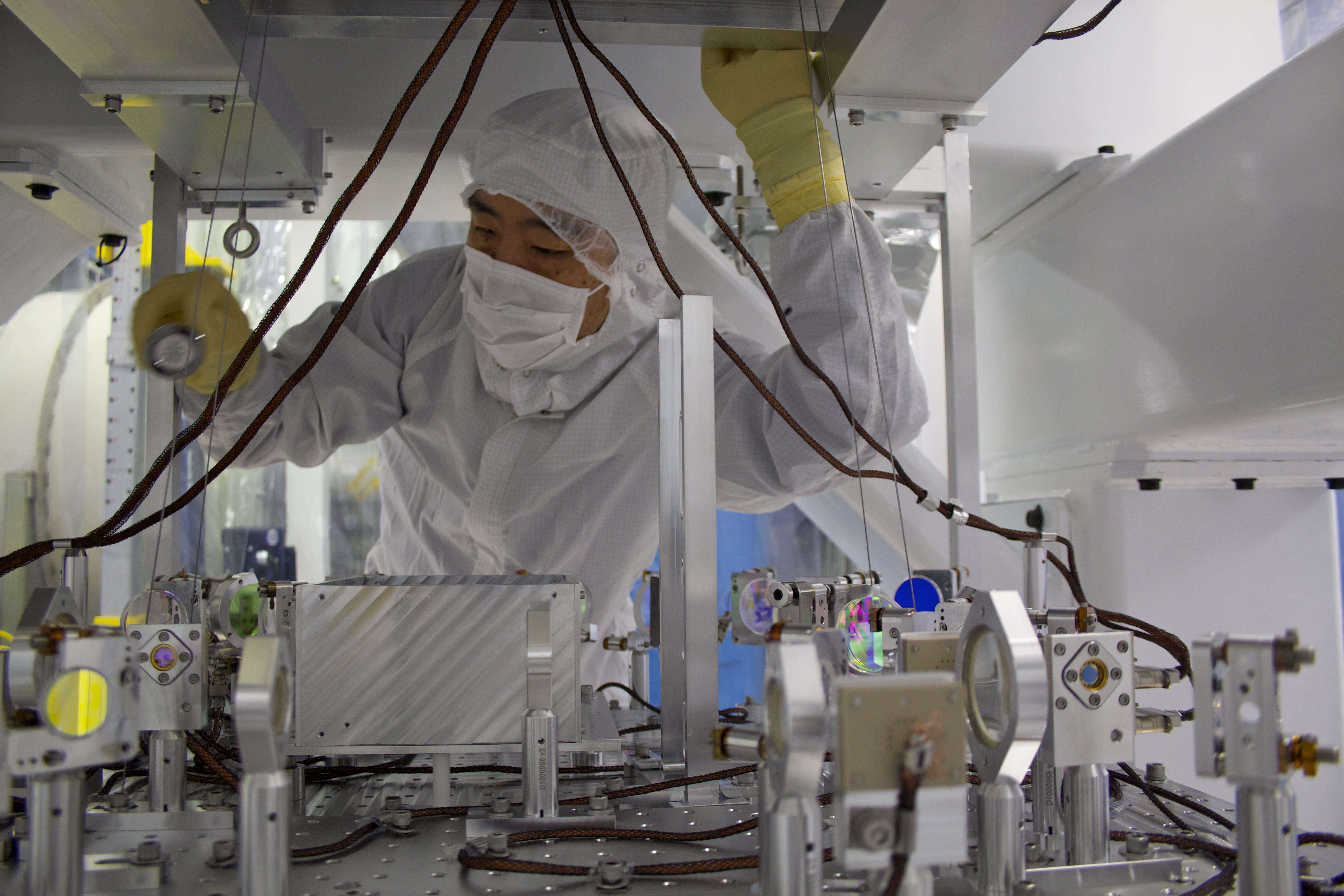
859 - JeffB and Andres out to HAM4 to make adjustments to SR2
900 – 1200, Mitch & Gerardo working at LVEA test stands
0920 - 1020 RichardM to EY to check on TMS signaling error
930 – MindyJ doing TCS plumbing inspection in LVEA
931 – Jim to CER to investigate H1IOPSUSAUXH56 failure
936 – 959 – Sheila out to LVEA racks
941 – 1025 Jax, Alexa to EX
1039 - 1124 – Karen to EX
1000 – Keita and Corey at EY for TMS work
1115-1200, 1322 – Jax working on ISCTEY in LVEA Squeezer Bay
1159 – LVEA rollup door near CER used
1310-1325 Betsy down to EY briefly for parts
1402 – 1310 JohnW plowing X-arm with tractor
1415 – Fire Alarm testing in OSB (HFD)
1426 – 1537 Kyle Soft Closing GV-7 (WP4430)
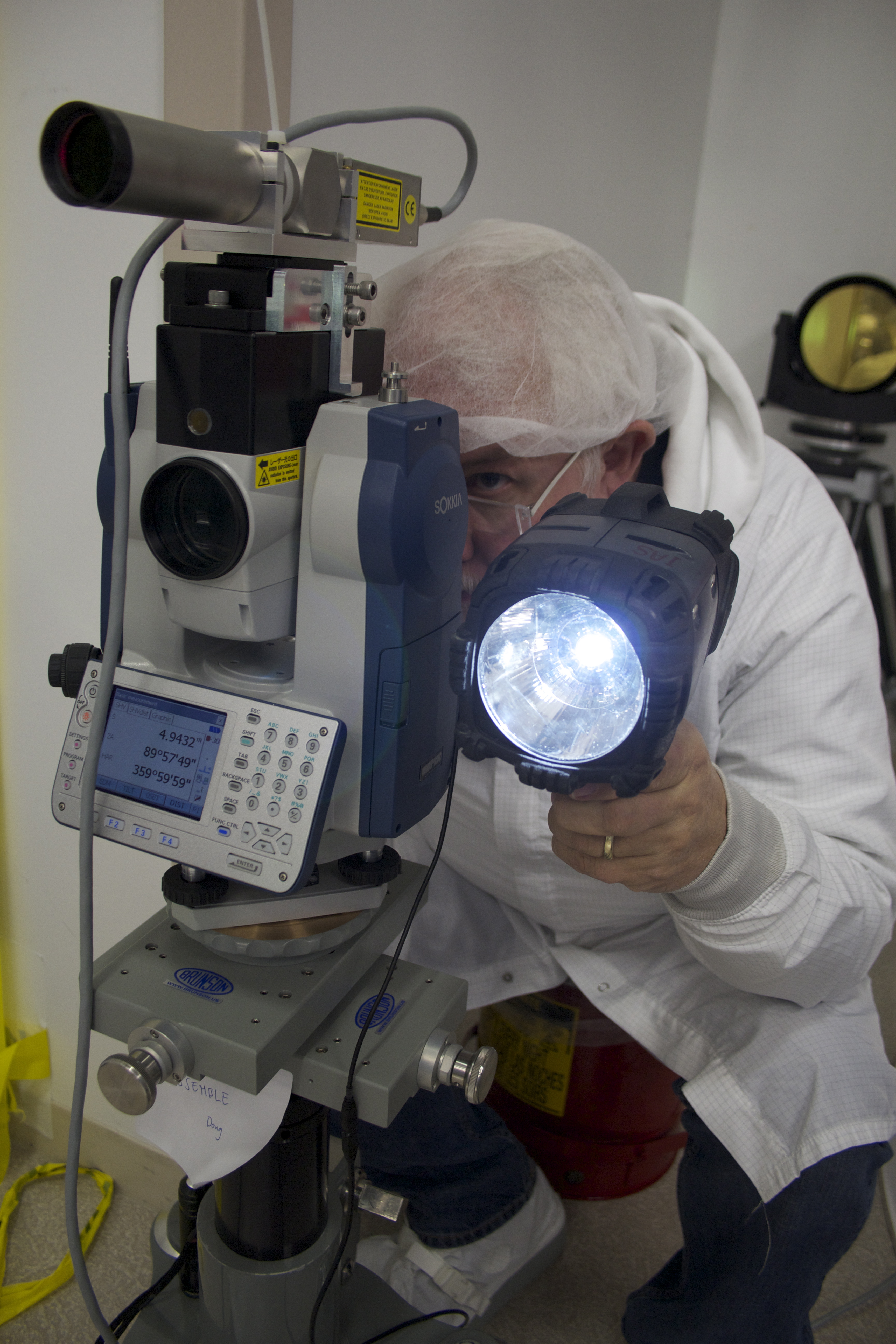
1450 – Arnaud taking measurements at EX
1523 – JeffL and JeffB working at HAM5 cleanroom


Evan, Daniel
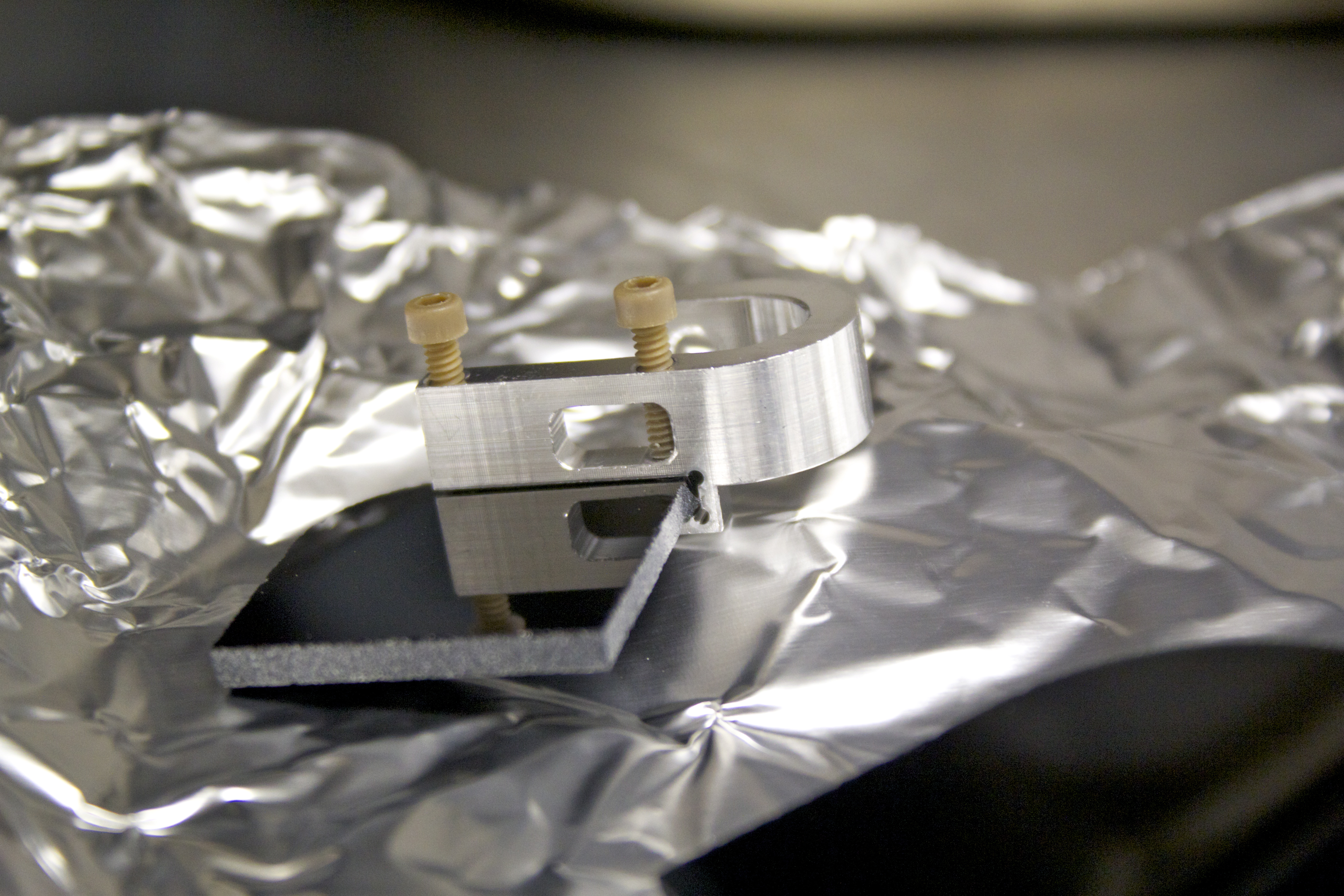
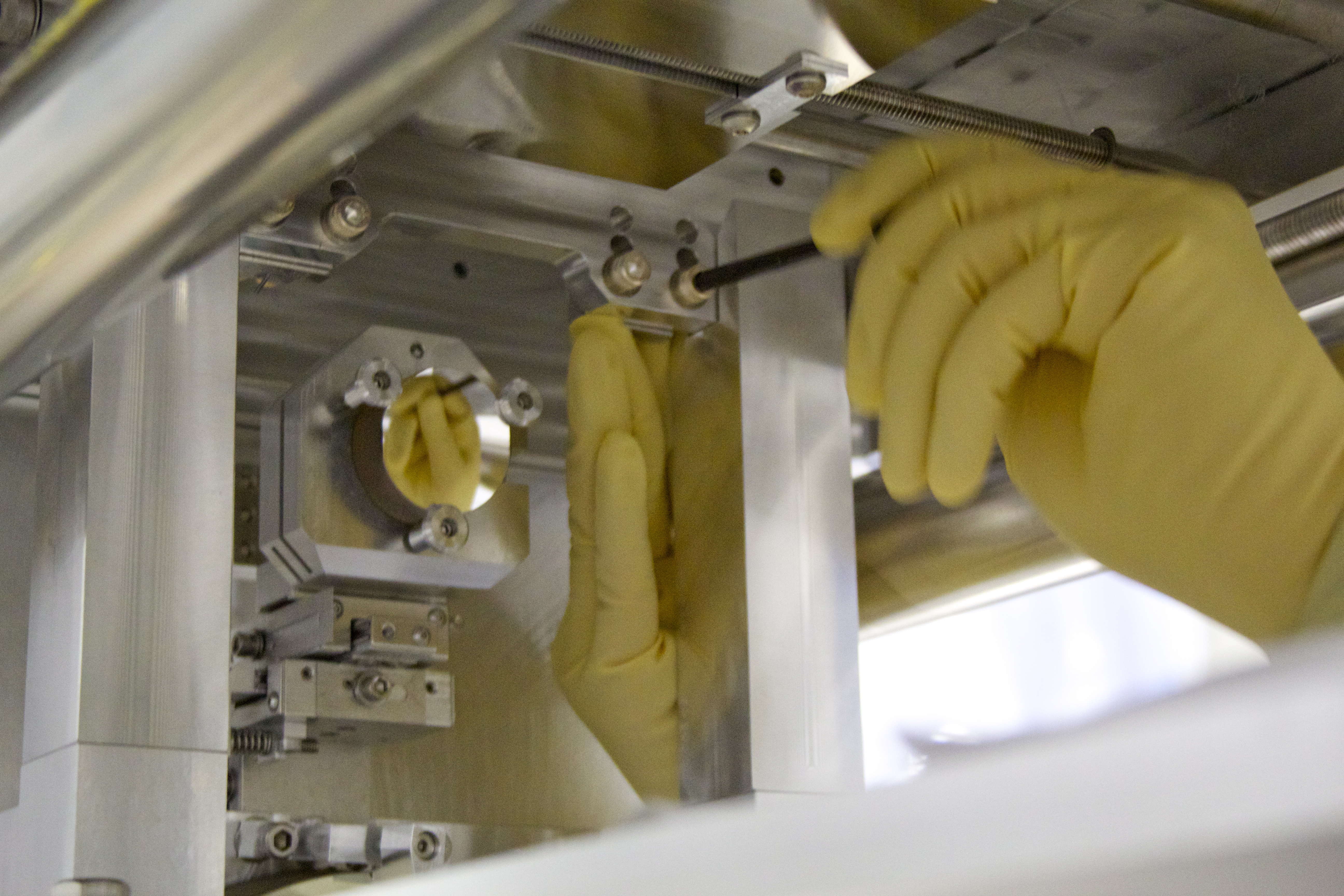
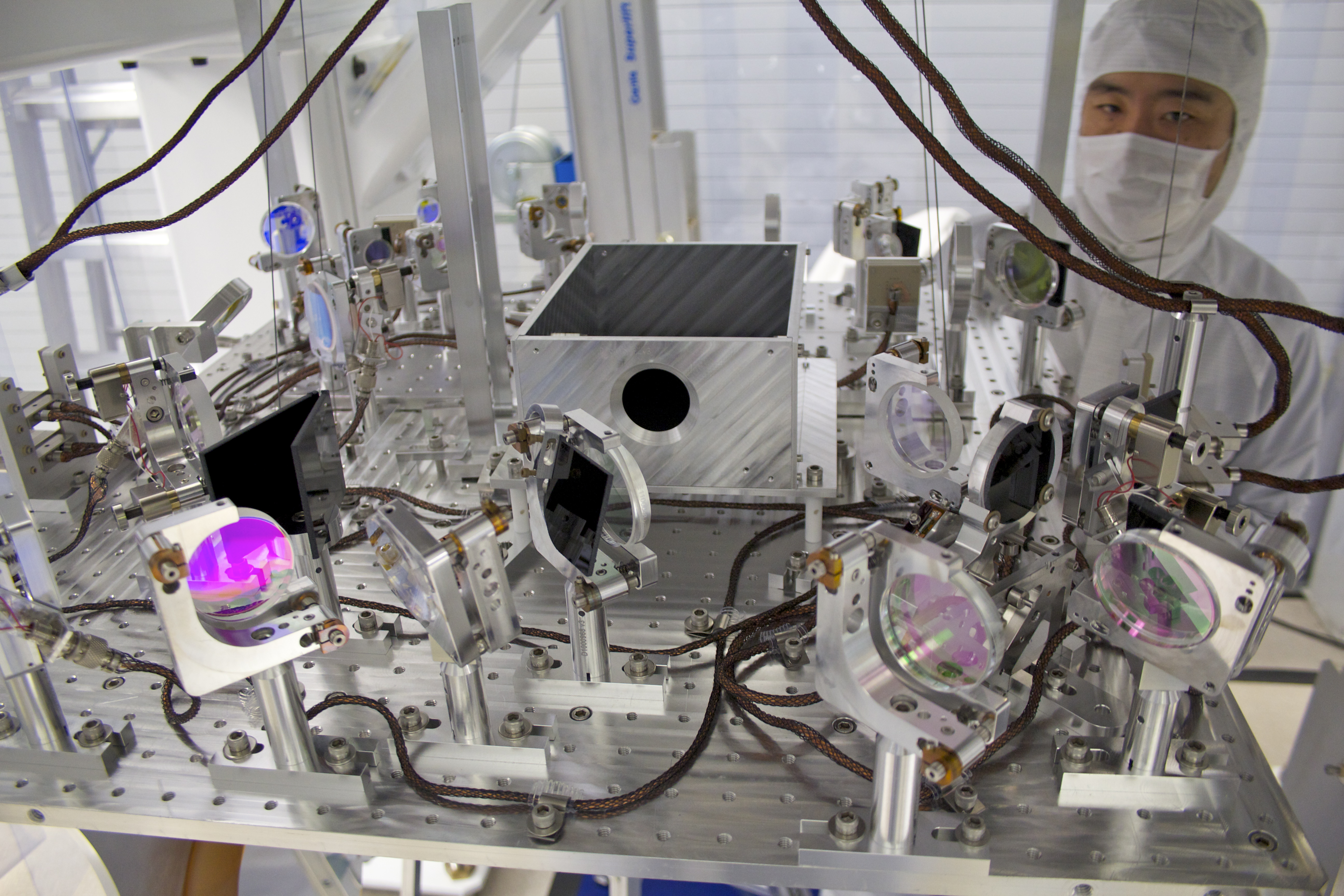
We found that the controls cable is missing from the second delay line, The cable we need is ISC-332 (DB25). We did not find any cable with this number, but we found two ISC-323. One is a DB25, the other a DB15. ISC-323 is for a shutter on ISCT6 (DB15). We think that ISC-332 (DB25) has been mislabeled. Unfortunately, it was pulled to the AS port rather than REFL.