[Keita, JoeG, Alexa and Kiwamu]
We continued working on the installation of HAM1 optics today. We did two major missions:
-
Insertion of another BS in the REFL path
-
Coarse placement of the tip-tilts
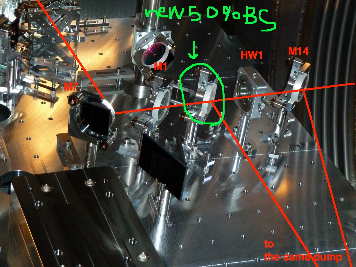
Insertion of a 50 % BS in the REFL path
We've been worried that the 90% S-pol BS, which we installed on this Monday (see alog 7851), may not give us a big enough safety margin to prevent the REFL beam from damaging the PDs. Today we decided to put another 50% BS to attenuate the power a bit more. We unpacked the one we removed on this Monday (see alog 7851) and put it back on the table. It was installed between M1 and HW1 (see the layout D1000313-v10) because it is designed for P-pol. To accommodate it we shifted the position of M14 and HW1 by 2 inches toward HAM2. The reflected light from this new BS was directed such that it is dumped by the pre-installed high power beam dump (HBD). Also HBD was shifted toward the East by 12 inches so that the incident angle of M14 and the new BS doesn't have to be far from 45 degrees.
Of course insertion of this new BS shifted the alignment of the downstream and therefore we realigned them. Finally M7 was steered such that the beam hits the center of the upper periscope on ISCT1 through the viewport and light pipe. Once we re-aligned them Paul confirmed that the beam on ISCT1 was reasonably back to where it was. So we are good.
Also during the alignment we noticed that the beam was too high at HW1 by ~ a few mm and M2 by 1 inch. We asked Paul to check the alignment biases on MC1-3, IM1-4 and PRM and he confirmed that they stayed the same these days. So we guess it has been like this and we had not been careful enough to notice this misalignment.
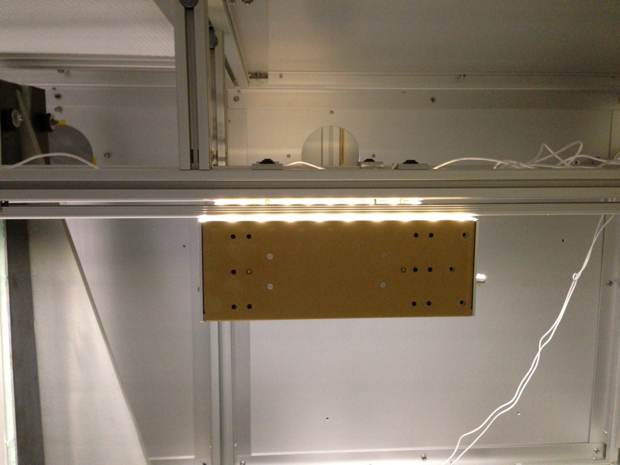
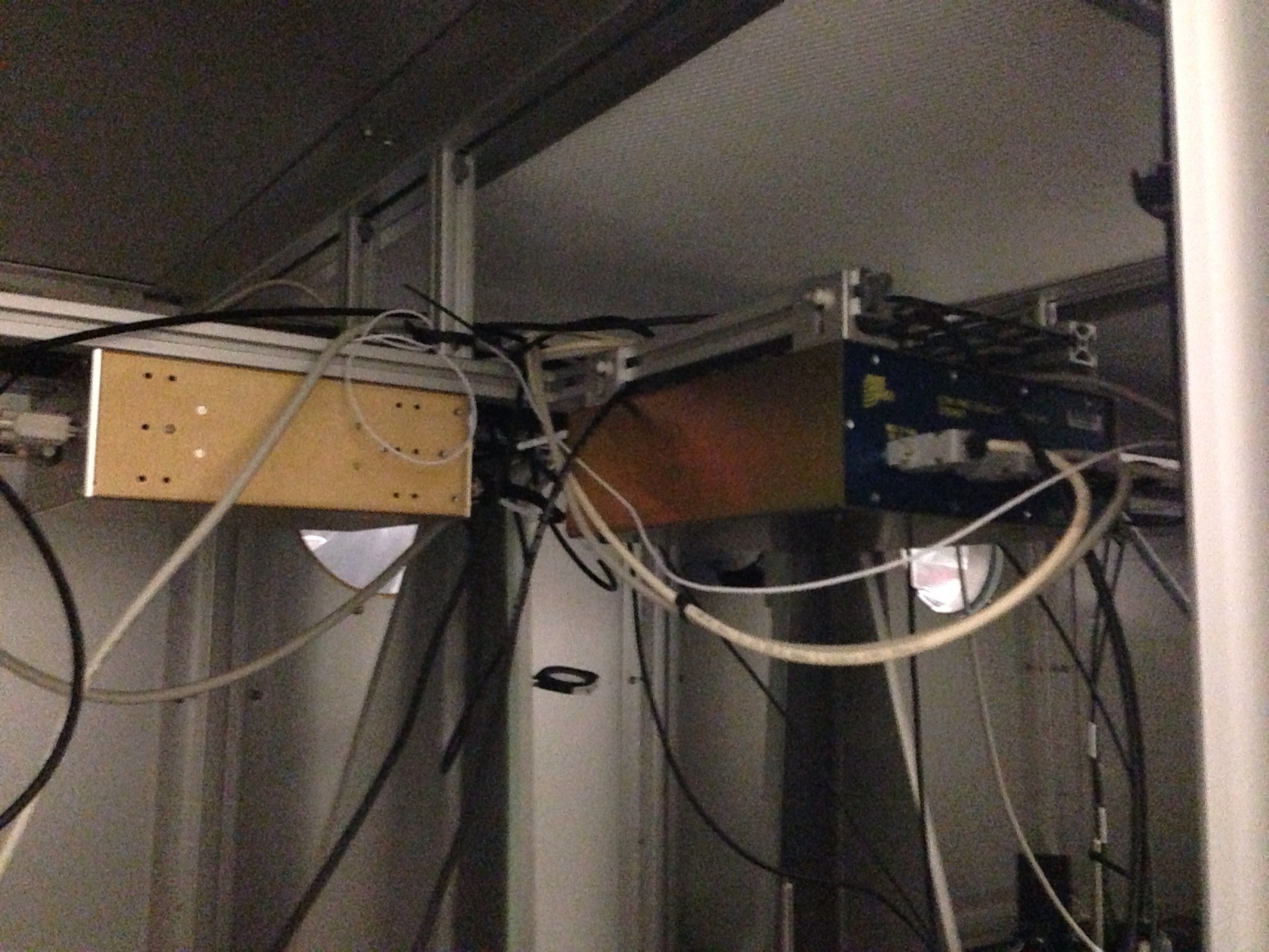
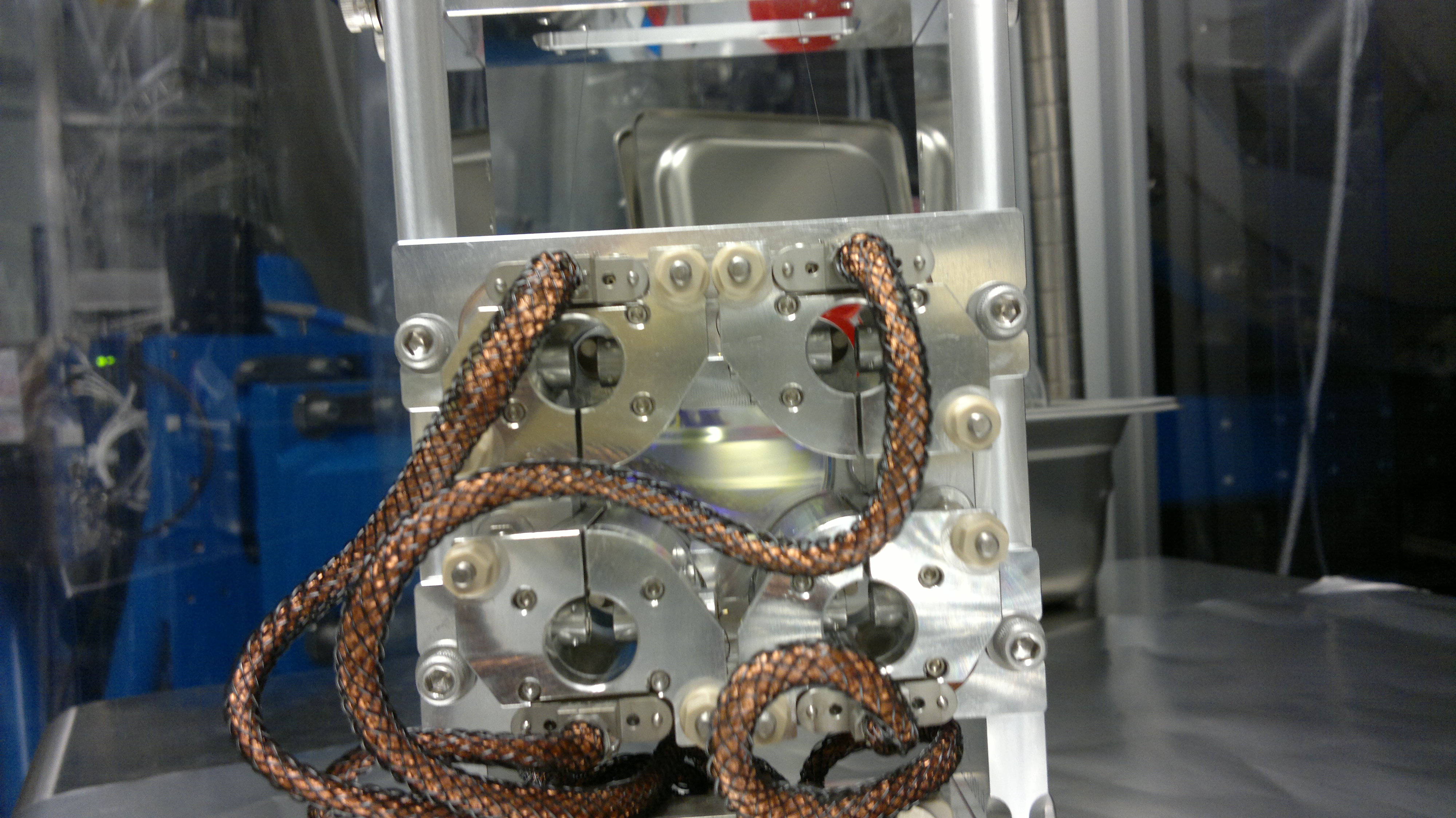
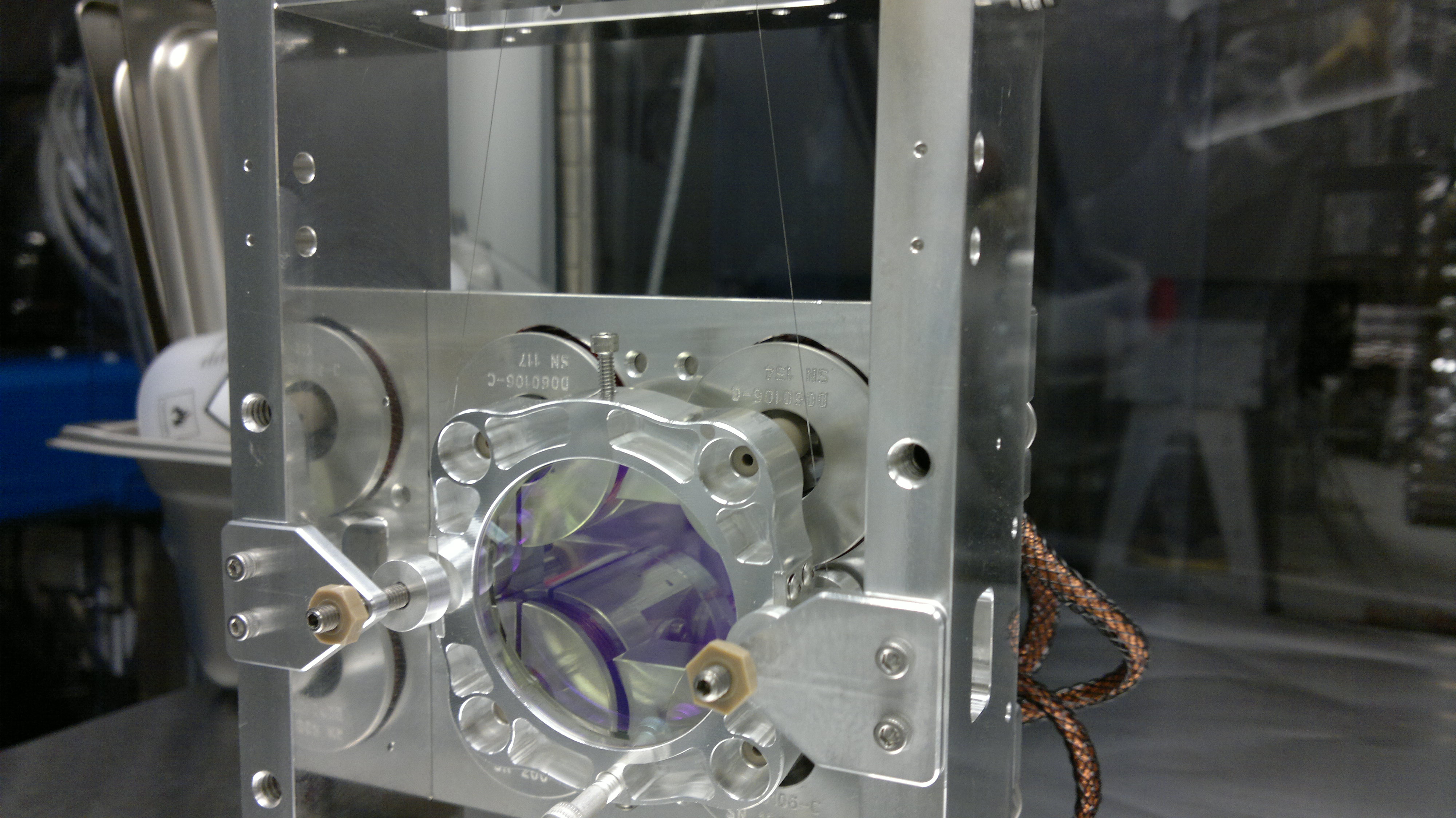
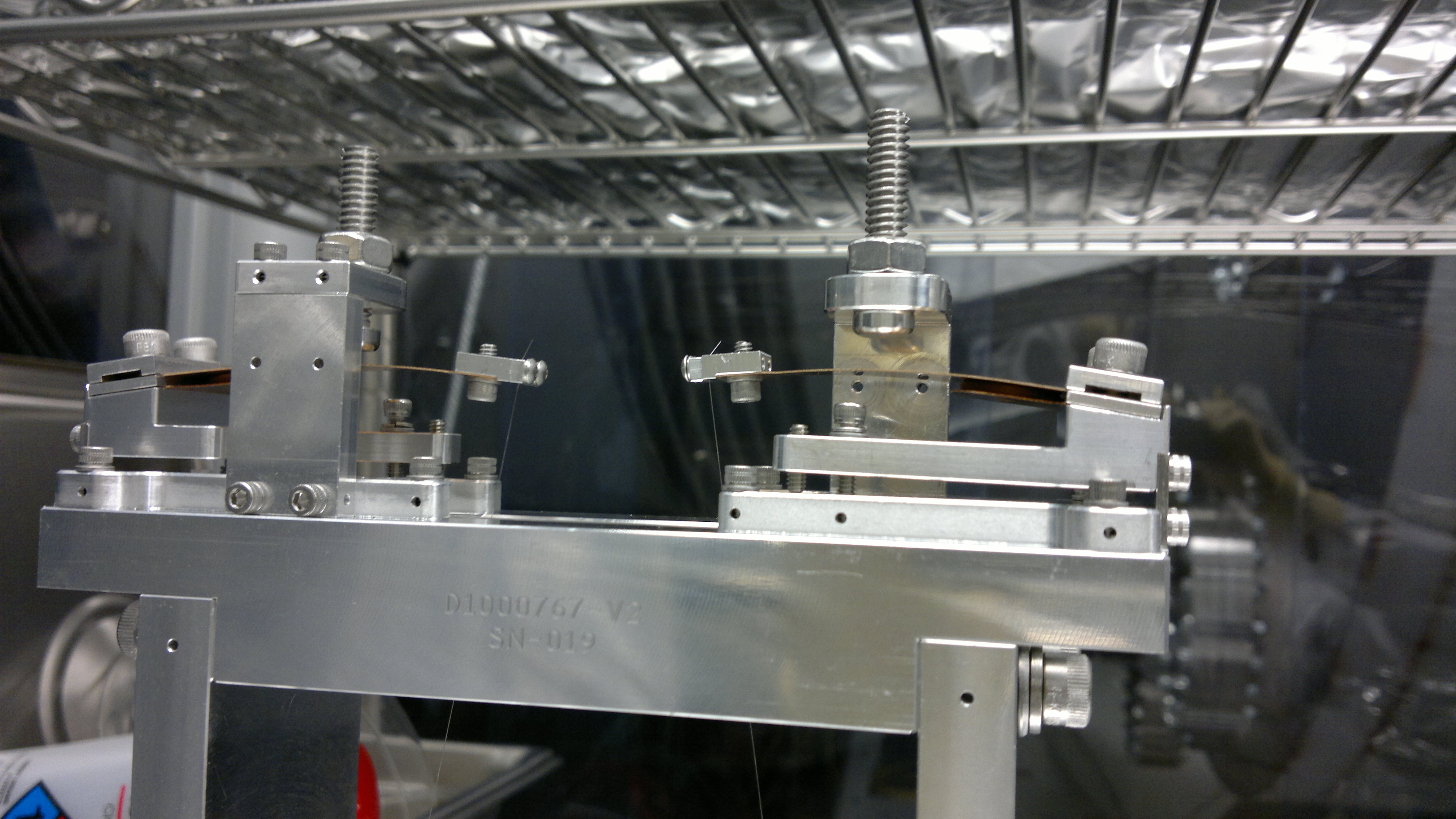
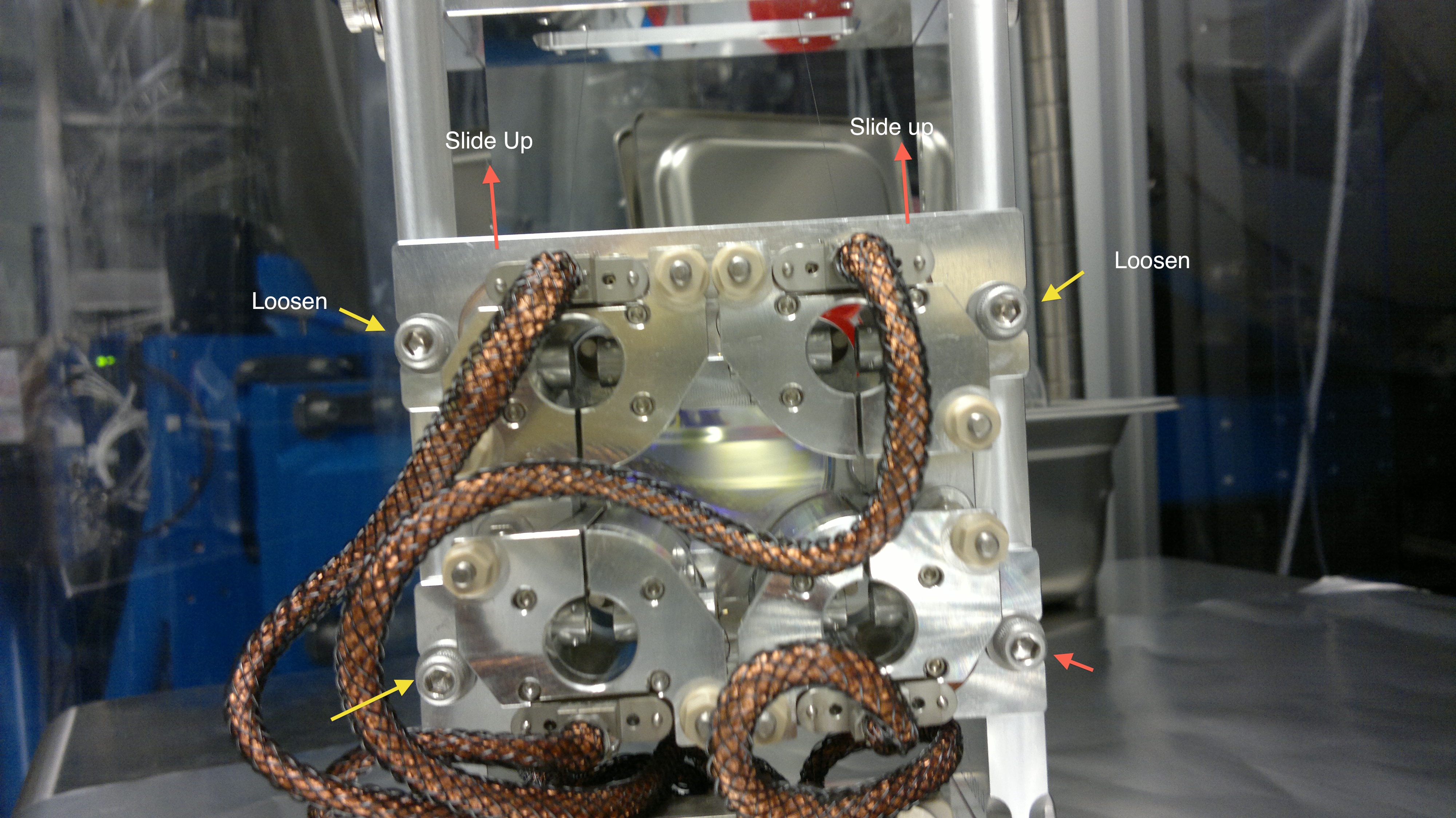
Adjustment of Tip-tilts:
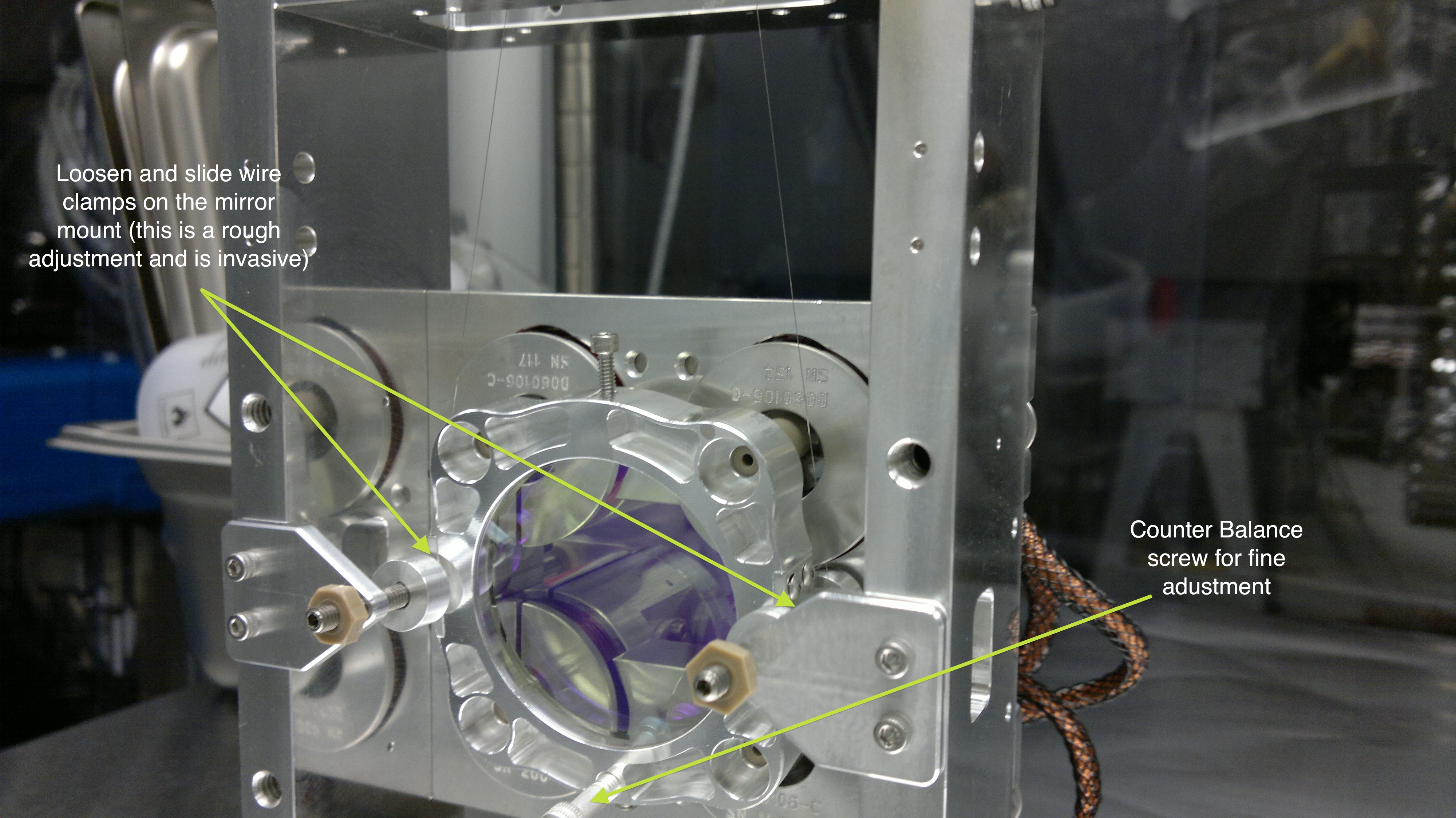
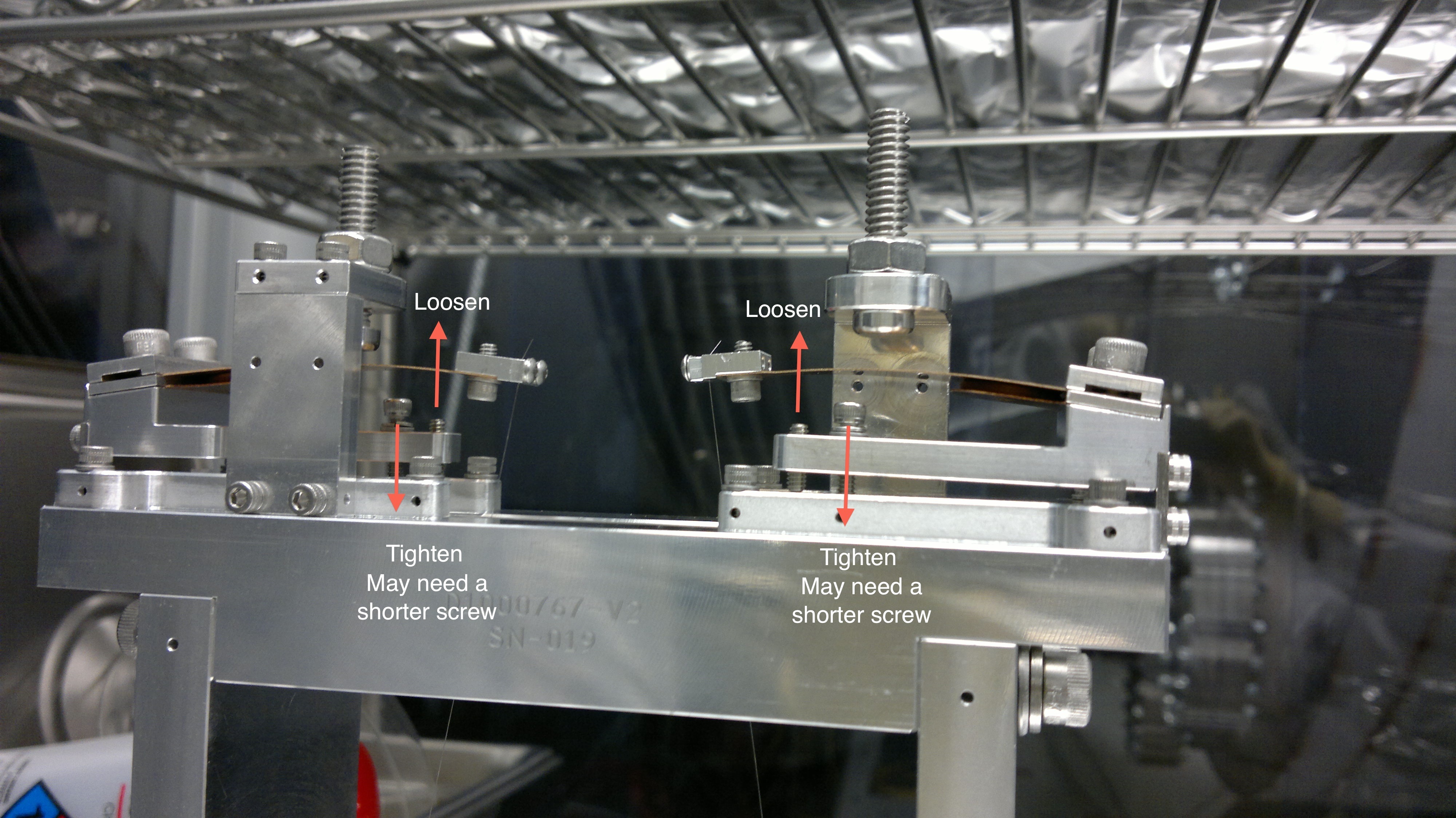
Keita managed to tune the height of the mirror on the tip-tilts (see the previous alog #7870 about tip-tilts) by replacing the screws by shorter ones and tightening them down. Then after a long time of balancing the mirror holder and centering OSEM, we put them in place coarsely.
Before placing them we adjusted the pitch of the mirror by using a laser pointer as a a optical lever for measuring the horizontality of the reflected light. Then Joe started adjusting the centering of the OSEM and their flags. Both of two tip-tilts showed a similar symptom at the beginning --- the mirror holder was off as if it was shifted along its plane horizontally. RM2 had a bigger horizontal displacement in the mirror holder by about 5 mm or so. RM1 was somewhat smaller. Somehow Joe empirically figured out a way to adjust this horizontal shift. He loosened the four screws which support the entire blade structure on top of the suspension cage and slided to obtain a good horizontal position. Later on Keita came over and told us a way to adjust it, which Bram told him. Interestingly it coincided what Joe did. By looking at the flags, we could tell that the they are well-centered with a precision of roughly 1 mm or perhaps less. Note that all the adjustment described here was done on the HAM1 in-vac table in order to have a flat and leveled surface.
One (new) concern :
The insertion depth of OSEMs look different among the two tip-tilts. One has all OSEMs inserted deeper so that they stick out by about 2 cm toward the mirror holder while the other is about 5 mm or so. We are not sure what is right and what is wrong for this. Hmmmm...